
Related Manuals for Estun Summa ED3L Series


Summary of Contents for Estun Summa ED3L Series
- Page 1 2023 Summa ED3L PN Series AC Servodrive Product Manual MODEL: ED3L-□□APA ESTUN AUTOMATION CO.,LTD.
-
Page 2: About This Manual
This manual provides the information required for the Selection, Wiring, Connection, Settings, Trial Operation, Tuning and Functions of the Summa ED3L Series AC Servo Drive (referred to as ED3L). Read and understand this manual to ensure correct usage of the product. - Page 3 -2147483648 to +2147483627 UINT8 Unsigned 8 bit 0 to 255 UINT16 Unsigned 16 bit 0 to 65535 UINT32 Unsigned 32 bit 0 to 4294967295 STRING String value (reserved) Document Version: V1.03 (May. 2021) © 2023 ESTUN Automation Co., Ltd. All right reserved.
-
Page 4: Symbols
Pn000.0 Servo ON − Pn000.1 Forward Drive Prohibit Input (P-OT) − Pn000.2 Reverse Drive Prohibit Input (N-OT) − Pn000.3 Reserved parameter (Do not change) − Document Version: V1.03 (May. 2021) © 2023 ESTUN Automation Co., Ltd. All right reserved. -
Page 5: Safety Precautions
Always use a Noise Filter to minimize the effects of electromagnetic interference. Always use a Motor and Drive in one of the specified combinations. Never touch a Drive or Motor with wet hands. Document Version: V1.03 (May. 2021) © 2023 ESTUN Automation Co., Ltd. All right reserved. -
Page 6: Storage Precautions
I/O Signal Cables and Encoder Cables. The wiring length of the encoder is up to 20 meters. Minimize the frequency that the power supply is turned ON and OFF. Document Version: V1.03 (May. 2021) © 2023 ESTUN Automation Co., Ltd. All right reserved. -
Page 7: Operation Precautions
When disposing of the product, treat it as ordinary industrial waste. However, local ordinances and national laws must be observed. Implement all labeling and warnings as required. CAUTION Document Version: V1.03 (May. 2021) © 2023 ESTUN Automation Co., Ltd. All right reserved. -
Page 8: Table Of Contents
3.4.4 Motor Connection Diagram......................3-23 3.4.5 Motor Power Cable Description ..................... 3-23 3.4.6 Power Input Wiring Specifications ....................3-27 3.4.7 Power Input Wiring Example ......................3-27 Document Version: V1.03 (May. 2021) © 2023 ESTUN Automation Co., Ltd. All right reserved. - Page 9 5.8 Torque Limit ............................5-13 5.8.1 Internal Torque Limits ........................5-14 5.8.2 External Torque Limits ........................5-15 5.9 SEMI F47 Function ..........................5-16 Chapter 6 PROFINET Communication................... 6-19 Document Version: V1.03 (May. 2021) © 2023 ESTUN Automation Co., Ltd. All right reserved. viii...
- Page 10 8.1.2 Control Block Diagram ........................8-2 8.1.3 Tuning Process ..........................8-3 8.1.4 Precautions Before Tuning ....................... 8-4 8.2 Tuning Modes ............................8-4 8.2.1 Tuning-Less ............................8-4 Document Version: V1.03 (May. 2021) © 2023 ESTUN Automation Co., Ltd. All right reserved.
- Page 11 10.2 Parameters Detailed ......................... 10-18 10.3 Parameter Quick Query Table ......................10-45 Chapter 1 1 Other ........................10-52 1.1 Bleed resistance selection ........................10-52 1.2 Encoder Cable Calculation ........................ 10-58 Document Version: V1.03 (May. 2021) © 2023 ESTUN Automation Co., Ltd. All right reserved.
-
Page 12: Chapter 1 Ed3L Servo Drive
Chapter 1 ED3L Servo Drive 1.1 Product Features As a new single-axis AC servo product from ESTUN, ED3L is designed with its excellent performance and practical control functions to create a complete set of solutions with the best cost performance for customers. -
Page 13: Interpreting The Nameplate
0.4 kW Marking Specification 0.75 kW 200 V 1.0 kW 400 V 1.5 kW 2.0 kW Marking Specification 3.0kW Serial encoder 5.0 kW Wire-saving encoder 7.5 kW Document Version: V1.03 (May. 2021) © 2023 ESTUN Automation Co., Ltd. All right reserved. -
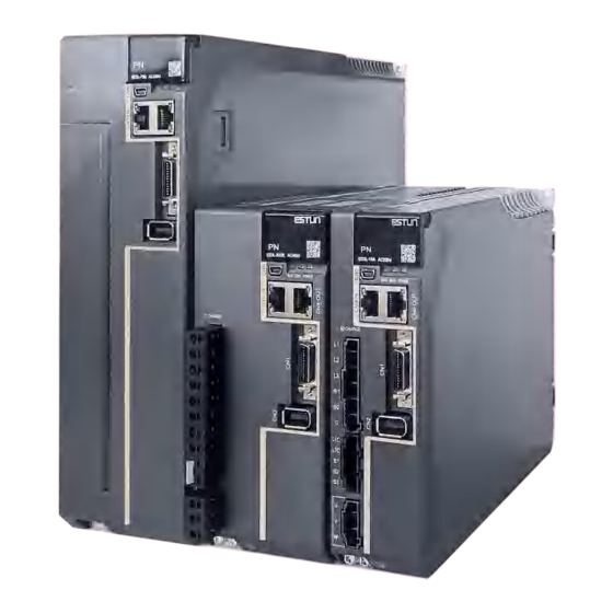
Page 14: Part Names
Motor terminals while this indicator is lit, in case the electric shock. USB Terminals Standard Mini USB Type-B Profinet Terminals Standard RJ-45 terminal IO Signal Terminals Connection terminals for sequence IO signals Document Version: V1.03 (May. 2021) © 2023 ESTUN Automation Co., Ltd. All right reserved. - Page 15 RUN: running indicator lamp communication indicators ERR: Error indicator lamp POWER: power on indicator lamp Profinet Output Connector Connects to an Profinet device or be vacant Document Version: V1.03 (May. 2021) © 2023 ESTUN Automation Co., Ltd. All right reserved.
- Page 16 2kW~3kW are similar in appearance and have the same components. Name Description Panel Operator A module for status displays and parameter settings. Socket for USB communication cable when using ESView USB Connector V4 on PC. Document Version: V1.03 (May. 2021) © 2023 ESTUN Automation Co., Ltd. All right reserved.
- Page 17 Connector for the drive’s main circuit cables. Control Circuit Connector Connector for the drive control circuit cables. Motor Power Cable Connector for the motor power cables. Connector Document Version: V1.03 (May. 2021) © 2023 ESTUN Automation Co., Ltd. All right reserved.
- Page 18 ON, do not touch the main circuit and motor terminals at this time to avoid electric shock. IO Signal Connection Port Socket for IO signal connectors. Document Version: V1.03 (May. 2021) © 2023 ESTUN Automation Co., Ltd. All right reserved.
-
Page 19: Ratings And Specifications
Single-phase AC 200V 240V, -15% +10%, 50Hz/60Hz Control Power 400VAC Single-phase AC 200V 440V, -15% +10%, 50Hz/60Hz Control Mode SVPWM control Serial encoder: Feedback 17 bits absolute magnetoelectric encoder Document Version: V1.03 (May. 2021) © 2023 ESTUN Automation Co., Ltd. All right reserved. - Page 20 Sync Manager output, and SM3: Process data input FMMU 0: Mapped in process data output (RxPDO) area. FMMU FMMU 1: Mapped in process data input (TxPDO) area. Document Version: V1.03 (May. 2021) © 2023 ESTUN Automation Co., Ltd. All right reserved.
-
Page 21: Dimensions
Note: When operating from a single-phase power supply for the ED3L-15AEA (rated power 1.5 kW), please deratify to 1.2 kW. 1.6 Dimensions Rated power from 50W to 400W Document Version: V1.03 (May. 2021) © 2023 ESTUN Automation Co., Ltd. All right reserved. 1-10... - Page 22 Rated power from 750W to 1kW Grounding terminals 2×M4 (75) Unit: mm Rated power from 1.5kW to 2kW 400VAC, rated power from 1kW to 1.5kW Document Version: V1.03 (May. 2021) © 2023 ESTUN Automation Co., Ltd. All right reserved. 1-11...
- Page 23 400VAC, rated power from 2kW to 3kW Grounding terminals 2*M4 Unit: mm 400VAC, rated power from 5kW to 7.5kW Grounding terminals Unit: mm 2*M4 D:\黄诗凡工作文件\EC型\Summa ED3L系列总线型交流伺服驱动器产品手册-V1.05 - (黄诗凡).docx Document Version: V1.03 (May. 2021) © 2023 ESTUN Automation Co., Ltd. All right reserved. 1-12...
-
Page 24: System Configuration
Single-phase, 200 VAC to 240 VAC Circuit Breaker USB Cable Noise Filter EtherCAT Cables I/O Signals Cable Magnetic Contactor External Regenerative Resistor Motor Power Grounding Supply Cable Encoder Cable Document Version: V1.03 (May. 2021) © 2023 ESTUN Automation Co., Ltd. All right reserved. 1-13... - Page 25 Three-phase, 200 VAC to 240 VAC Circuit Breaker Noise Filter USB Cable Magnetic Contactor EtherCAT Cables I/O Signals Cable External Regenerative Resistor Motor Power Grounding Supply Cable Encoder Cable Document Version: V1.03 (May. 2021) © 2023 ESTUN Automation Co., Ltd. All right reserved. 1-14...
- Page 26 For EtherCAT networking. IO cable (user supplied) External Regenerative Resistor Connected between B1 and B2 when bus capacitance is insufficient. Power cable Ground wire Encoder cable Document Version: V1.03 (May. 2021) © 2023 ESTUN Automation Co., Ltd. All right reserved. 1-15...
-
Page 27: Minimum System Configuration
Protection against external noise interference from the power cable, with the Noise filter current rated at 10A or 20A. Electromagnetic ON/OFF control of the input circuit. contactor Document Version: V1.03 (May. 2021) © 2023 ESTUN Automation Co., Ltd. All right reserved. 1-16... -
Page 28: Peripheral Devices Specification
3-phase AC 380V 440V 50Ω 80W 40Ω 20A(3-phase) ED3L-50DEA 3-phase AC 380V 440V 35Ω 80W 20Ω 25A(3-phase) ED3L-75DEA 3-phase AC 380V 440V 35Ω 80W 20Ω Document Version: V1.03 (May. 2021) © 2023 ESTUN Automation Co., Ltd. All right reserved. 1-17... -
Page 29: Part Numbers
EM3G- EM3G-18DA224 EC3P-B9314- (with brake) 18DA224 EM3A- EC3P-N8313- (without brake) 30DLA224 EC3P-B8313- (with brake) ED3L-30D EC3S-A1924- (Absolute) EM3G- EC3P-N8212- (without brake) 29DLA244 EC3P-B8212- (with brake) Document Version: V1.03 (May. 2021) © 2023 ESTUN Automation Co., Ltd. All right reserved. 1-18... - Page 30 : The last two digits of the cable indicate the length (e.g. 1M5, 03, 05, 08, 10, 12, 15, 20), in metres (mm). Flexible cables are also available, marked with "-RX". Document Version: V1.03 (May. 2021) © 2023 ESTUN Automation Co., Ltd. All right reserved. 1-19...
-
Page 31: Chapter 2 Installation
Drive and mount it securely in the mounting holes (The number of mounting holes depends on the size of the Drive). Figure 2-1 Base-mounted diagram Mounting plate Ariflow Base Ariflow Document Version: V1.03 (May. 2021) © 2023 ESTUN Automation Co., Ltd. All right reserved. -
Page 32: Mounting Hole Dimensions
Machining Diagram for Machining Diagram for Machining Diagram for Mounting Holes Mounting Holes Mounting Holes (Mounting pitch) (Mounting pitch) (Mounting pitch) Wiring diagram for mounting holes at 400VAC Document Version: V1.03 (May. 2021) © 2023 ESTUN Automation Co., Ltd. All right reserved. -
Page 33: Mounting Interval
2.4 Mounting Interval Installing One Drive in a Control Cabinet When installing a single Drive use Figure 2-2 as a reference for free space around the installation. Document Version: V1.03 (May. 2021) © 2023 ESTUN Automation Co., Ltd. All right reserved. - Page 34 The ED3L 50D and 75D drives do not allow close mounting due to wiring, and the distance between drives is to be confirmed upon assembly of the cable, for which 80mm is the recommended Document Version: V1.03 (May. 2021) © 2023 ESTUN Automation Co., Ltd. All right reserved.
-
Page 35: Chapter 3 Wiring And Connecting
Install molded-case circuit breakers and other safety measures to provide protection against short circuits in external wiring. Document Version: V1.03 (May. 2021) © 2023 ESTUN Automation Co., Ltd. All right reserved. -
Page 36: Countermeasures Against Noise
You must attach Noise Filters in appropriate places to protect the Drive from the adverse effects of noise. Figure 3-1 is an example of wiring for countermeasures against noise. Document Version: V1.03 (May. 2021) © 2023 ESTUN Automation Co., Ltd. All right reserved. - Page 37 Separate input lines from output lines. Do not place input lines and output lines in the same duct or bundle them together. Noise Filter Noise Filter Ground Ground plate plate Noise Filter Noise Filter Ground Ground plate plate Separate the circuits. Document Version: V1.03 (May. 2021) © 2023 ESTUN Automation Co., Ltd. All right reserved.
- Page 38 Control Cabinet Drive Noise Filter Drive Grounding Ground Plate Document Version: V1.03 (May. 2021) © 2023 ESTUN Automation Co., Ltd. All right reserved.
-
Page 39: Recommended Emc Filters
For all grounding, use a single grounding point. Cable Fixing It is recommended that all cable shields are secured with a conductive metal clamp to the ground plate. For example: Document Version: V1.03 (May. 2021) © 2023 ESTUN Automation Co., Ltd. All right reserved. -
Page 40: Io Signal Cable Selection And Wiring
If the IO signal is a BK (holding brake) signal, the following requirements should be met: the 24V power supply for the IO signal should be independent of the 24V power supply of the motor holding brake. Document Version: V1.03 (May. 2021) © 2023 ESTUN Automation Co., Ltd. All right reserved. -
Page 41: Basic Wiring Diagrams
The external wiring of the input signals can use the co-cathode method or the co-anode method. c: The connection of the battery is only for the Motors with the absolute encoder. Document Version: V1.03 (May. 2021) © 2023 ESTUN Automation Co., Ltd. All right reserved. - Page 42 The external wiring of the input signals can use the co-cathode method or the co-anode method. c: The connection of the battery is only for the Motors with the absolute encoder. Document Version: V1.03 (May. 2021) © 2023 ESTUN Automation Co., Ltd. All right reserved.
- Page 43 External Regenerative Resistor The input signal can be wired with a common cathode or common anode. Only servo motors with absolute encoders use the battery case wiring. Document Version: V1.03 (May. 2021) © 2023 ESTUN Automation Co., Ltd. All right reserved.
-
Page 44: Terminals Arrangements
- ALM+ - COIN- COIN+ Shell - - Main circuit terminals N-OT - P-OT - S-ON - Encoder terminals (CN2) PG5V PG0V BAT+ BAT- Shell Document Version: V1.03 (May. 2021) © 2023 ESTUN Automation Co., Ltd. All right reserved. 3-10... - Page 45 - - Main N-OT - circuit P-OT - terminals S-ON - ㊀ Encoder terminals (CN2) Control circuit terminals PG5V PG0V Motor terminals BAT+ BAT- Shell Document Version: V1.03 (May. 2021) © 2023 ESTUN Automation Co., Ltd. All right reserved. 3-11...
- Page 46 Chapter 3 Wiring and Connecting 400VAC, rated power from 1kW to 1.5kW IO terminal CN1 Housing Main circuit terminals Encoder terminal Control circuit terminals Motor power terminals Housing Document Version: V1.03 (May. 2021) © 2023 ESTUN Automation Co., Ltd. All right reserved. 3-12...
- Page 47 Chapter 3 Wiring and Connecting 400VAC, rated power from 2kW to 3kW IO terminal CN1 Housing Main circuit terminals Encoder terminal Control circuit terminals Motor power terminals Housing Document Version: V1.03 (May. 2021) © 2023 ESTUN Automation Co., Ltd. All right reserved. 3-13...
- Page 48 ALM- - Hous ing ALM+ - COIN- COIN+ - - N-OT - P-OT - S-ON - ㊀ Encoder terminal PG5V PG0V BAT+ BAT- Hous ing Document Version: V1.03 (May. 2021) © 2023 ESTUN Automation Co., Ltd. All right reserved. 3-14...
-
Page 49: Wiring The Power Supply To Drive
N to the negative pole. U, V, W Motor terminals Connects the U-phase, V-phase and W-phase of Motor Ground terminal Always connect this terminal to prevent electric shock. Document Version: V1.03 (May. 2021) © 2023 ESTUN Automation Co., Ltd. All right reserved. 3-15... - Page 50 B1 and B2. U, V, W Motor terminals Connects the U-phase, V-phase and W-phase of Motor Ground terminal Always connect this terminal to prevent electric shock. Document Version: V1.03 (May. 2021) © 2023 ESTUN Automation Co., Ltd. All right reserved. 3-16...
- Page 51 U, V, W Connect the U, V and W phases of the motor. connectors Grounding terminals Connect the power supply earth terminal for earthing. Document Version: V1.03 (May. 2021) © 2023 ESTUN Automation Co., Ltd. All right reserved. 3-17...
- Page 52 Grounding terminals Connect the power supply earth terminal for earthing. Power supply input L1, L2, L3 3-phase AC 380V 440V, -15% +10%, 50Hz/60Hz terminals Document Version: V1.03 (May. 2021) © 2023 ESTUN Automation Co., Ltd. All right reserved. 3-18...
-
Page 53: Wiring A Regenerative Resistor
Figure 3-2 is an example of connecting an external regenerative resistor for the drives rated power from 50W to 400W. Figure 3-2 Wires a regenerative resistor Connect an external regenerative resistor between terminals P and B Document Version: V1.03 (May. 2021) © 2023 ESTUN Automation Co., Ltd. All right reserved. 3-19... - Page 54 When an excternal regenerative resistor is connected, check and set Pn521.0 as 0 after the power up. Please check and confirm that the external regenerative resistor is mounted on non- combustible materials. Document Version: V1.03 (May. 2021) © 2023 ESTUN Automation Co., Ltd. All right reserved. 3-20...
-
Page 55: Wiring Procedure
Step 2 Peel off the sheath so that the conductor portion of the cable will protrude from the tip of the ferrule. 8mm to 9mm Step 3 Insert the cable into the ferrule (It should protrude 1 mm or more from the ferrule). 1mm or more Document Version: V1.03 (May. 2021) © 2023 ESTUN Automation Co., Ltd. All right reserved. 3-21... - Page 56 Step 9 When you have completed wiring, attach connection terminals to the Drive. NOTE The above wiring procedure is also applicable to the Motor Terminals. ----End Document Version: V1.03 (May. 2021) © 2023 ESTUN Automation Co., Ltd. All right reserved. 3-22...
-
Page 57: Motor Connection Diagram
EM3A-20D EM3A-30D EC3P-N8718-03 EC3P-N8718-05 EC3P-N8718-10 provided EM3G-09A EM3G-13A 2.0mm EMG-10A Provided EC3P-B8718-03 EC3P-B8718-05 EC3P-B8718-10 EMG-15A EMG-20A EC3P-N8214-03 EC3P-N8214-05 EC3P-N8214-10 provided EM3A-30D Provided EC3P-B8214-03 EC3P-B8214-05 EC3P-B8214-10 Document Version: V1.03 (May. 2021) © 2023 ESTUN Automation Co., Ltd. All right reserved. 3-23... - Page 58 Signal Color Signal Color Brown Brown Grey Grey Black Black Yellow/ Yellow/ green green White White Green Green Recommended wire diameter for B1 and B2:0.5mm Document Version: V1.03 (May. 2021) © 2023 ESTUN Automation Co., Ltd. All right reserved. 3-24...
- Page 59 Pin Signal Crimp terminal EC3P-B9718-□□ Motor side Drive side View from t he ins ert s ide of pin s Pin Signal Pin Signal Crimp terminal Document Version: V1.03 (May. 2021) © 2023 ESTUN Automation Co., Ltd. All right reserved. 3-25...
- Page 60 EC3P-B9314-□□ Motor side Drive side View from t he insert side of pin s Pin Signal Pin Signal Crimp terminal Short wiring: BVR 1.5 mm² Document Version: V1.03 (May. 2021) © 2023 ESTUN Automation Co., Ltd. All right reserved. 3-26...
-
Page 61: Power Input Wiring Specifications
200VAC Rated power from 50W to 400W Use single-phase 200 VAC to 240 VAC as the power input for the Drives rated power from 50W to 400W. Document Version: V1.03 (May. 2021) © 2023 ESTUN Automation Co., Ltd. All right reserved. 3-27... - Page 62 Drive QF[1] SA[3] FLT[1] KM[2] Motor KM[1] Power Power KM[1] SA[1] KM[1] ㊀ KM[2] KM[1] Ry[1] SA[2] ALM- (For alarm Ry[1] ALM+ display) +24V PL[1] Document Version: V1.03 (May. 2021) © 2023 ESTUN Automation Co., Ltd. All right reserved. 3-28...
- Page 63 SA[1]: Surge Absorber 1 SA[2]: Surge Absorber 2 SA[3]: Surge Absorber 3 FLT[1]: Noise Filter Ry[1]: Relay PL[1]: Indicator lamp KM[1]: Magnetic Contactor (for control power supply) Document Version: V1.03 (May. 2021) © 2023 ESTUN Automation Co., Ltd. All right reserved. 3-29...
-
Page 64: Wiring The Encoder
EM3J-04A Absolute EC3S-A1724-03 EC3S-A1724-05 EC3S-A1724-10 EM3J-08A EM3A-15A Incremental EC3S-I1924-03 EC3S-I1924-05 EC3S-I1924-10 EM3A-15D EM3A-20A EM3A-20D EM3A-30A EM3A-30D EM3A-40D Absolute EC3S-A1924-03 EC3S-A1924-05 EC3S-A1924-10 EM3A-50DLA EM3GAll aircraft types Document Version: V1.03 (May. 2021) © 2023 ESTUN Automation Co., Ltd. All right reserved. 3-30... - Page 65 4 5 6 5 7 9 7 8 9 Pin Signal Pin Signal BAT+ BAT+ - - - - PG5V PG5V PG0V PG0V BAT- BAT- Shell Document Version: V1.03 (May. 2021) © 2023 ESTUN Automation Co., Ltd. All right reserved. 3-31...
- Page 66 View from t he insert side of pin s EM3A-10A 6 8 10 5 7 9 Pin Signal Pin Signal BAT+ BAT+ - - - - PG5V PG5V PG0V PG0V BAT- BAT- Shell Document Version: V1.03 (May. 2021) © 2023 ESTUN Automation Co., Ltd. All right reserved. 3-32...
- Page 67 View from t he ins ert s ide of pin s 6 8 10 5 7 9 Pin Signal Pin Signal BAT+ BAT+ - - - - PG5V PG5V PG0V PG0V BAT- BAT- Shell Document Version: V1.03 (May. 2021) © 2023 ESTUN Automation Co., Ltd. All right reserved. 3-33...
- Page 68 View from t he ins ert s ide of pin s 6 8 10 5 7 9 Pin Signal Pin Signal BAT+ BAT+ PG5V PG5V PG0V PG0V BAT- BAT- Shell Document Version: V1.03 (May. 2021) © 2023 ESTUN Automation Co., Ltd. All right reserved. 3-34...
-
Page 69: Battery Case Connection
Also, you can reset the alarms by ESView V4, for details, see ESView Help Manual. Step 7 Make sure the alarms have been cleared and the Drive operates normally. ----End Document Version: V1.03 (May. 2021) © 2023 ESTUN Automation Co., Ltd. All right reserved. 3-35... -
Page 70: I/O Signal Connections
Power supply for CN1-14, CN1-15 and CN1-16, connects to a DICOM1 Common 24 VDC or 0V. Power supply for CN1-17 and CN1-18, connects to a 24 VDC or DICOM2 Common Document Version: V1.03 (May. 2021) © 2023 ESTUN Automation Co., Ltd. All right reserved. 3-36... -
Page 71: Wiring Description
CL (Reverse External Torque Limit), G-SEL (Gain Selection), HmRef (Homing), Remote (Remoted Input). For the input signal allocation, see the section 5.7.1 Input Signal Allocations. Document Version: V1.03 (May. 2021) © 2023 ESTUN Automation Co., Ltd. All right reserved. 3-37... - Page 72 Detection), BK (Brake), PGC (Motor C-pulse), OT (Overtravel), RD (Motor Excitation), TCR (Torque Detection), Remote (Remoted output). For the output signal allocation, see the section 5.7.2 Output Signal Allocations. Document Version: V1.03 (May. 2021) © 2023 ESTUN Automation Co., Ltd. All right reserved. 3-38...
-
Page 73: Holding Brake Wiring
Table 3-1 lists brake specifications for each Motor matched with ED3L. Table 3-1 Brake specifications Voltage Holding torque Out of time Absorption Power Motor Model (N·m) (ms) time(ms) EM3A-A5A/01A 24V±10% 0.32 EM3A-02A/04A 24V±10% Document Version: V1.03 (May. 2021) © 2023 ESTUN Automation Co., Ltd. All right reserved. 3-39... -
Page 74: Touch Probe Wiring
The timing sequence between input signals and trigger is as shown in below. EXT1 EXT2 Touch Probe Rising edge Falling edge trigger NOTE For details about the function setting, see the section 错误!未找到引用源。错误!未找到引 用源。. Document Version: V1.03 (May. 2021) © 2023 ESTUN Automation Co., Ltd. All right reserved. 3-40... -
Page 75: Communication Connections
Connection Diagram Controller CN3-IN: CN3-IN CN4-OUT Connected by the OUT of the previous drive or controller. CN4-OUT: Connect to the next Drive's IN or not connect. Document Version: V1.03 (May. 2021) © 2023 ESTUN Automation Co., Ltd. All right reserved. 3-41... -
Page 76: Cable Description
Use category 5 (CAT5e SF/UTP) Ethernet communications cables for network connections. Metal shielded connectors are recommended to prevent signal interference. Metal shielded are recommended Use CAT5e SF/UTP Ethernet communications cables Document Version: V1.03 (May. 2021) © 2023 ESTUN Automation Co., Ltd. All right reserved. 3-42... -
Page 77: Usb Communication Cable
PC Cable Description You can purchase the USB Communication Cable provided by ESTUN, or you can purchase the commercially available products yourself. The plug connected to your PC is USB Type-A, and the plug connected to the Drive is Mini USB Type-B. -
Page 78: Chapter 4 Basic Settings
Press [▼] Key to decrease the set value. Data setting key ◀ To display parameter setting and set value. To shift to the next digit on the left. Document Version: V1.03 (May. 2021) © 2023 ESTUN Automation Co., Ltd. All right reserved. 4-44... -
Page 79: Basic Mode Selection
Figure 4-2. Figure 4-2 Select a basic mode Status Display Parameter Setting [◀ ] Monitor [◀ ] Utility Function [◀ ] Document Version: V1.03 (May. 2021) © 2023 ESTUN Automation Co., Ltd. All right reserved. 4-45... -
Page 80: Status Display Mode
Lit if Motor speed exceeds the Detection value preset in Pn503 (Default Detection value preset in Pn503 (Default (TGON) setting is 20 rpm). (TGON) setting is 20 rpm). Document Version: V1.03 (May. 2021) © 2023 ESTUN Automation Co., Ltd. All right reserved. 4-46... - Page 81 NOTE: When the Drive is in Servo Alarm State, you shall check and correct the fault according to the Alarm Number Display, and then, you can press [◄] key to try to clear the current alarm. Document Version: V1.03 (May. 2021) © 2023 ESTUN Automation Co., Ltd. All right reserved. 4-47...
-
Page 82: Parameter Setting Mode
Step 7 Press [ ] key three times, changing the value of the 4th digit from 0 to 3. Step 8 Press [◄] key twice, moving the flashing decimal point to the 2nd digit. Document Version: V1.03 (May. 2021) © 2023 ESTUN Automation Co., Ltd. All right reserved. 4-48... - Page 83 Middle four digits Bottom four digits IMPORTANT Only when the value is with sign or negative number, "−" is displayed. Lights when negative number is displayed Document Version: V1.03 (May. 2021) © 2023 ESTUN Automation Co., Ltd. All right reserved. 4-49...
- Page 84 Step 9 Press and hold [◄] key for 1 second or more to return to the display of the Pn504 parameter value, or press the [M] key to return to the display of the Pn504. ----End Document Version: V1.03 (May. 2021) © 2023 ESTUN Automation Co., Ltd. All right reserved. 4-50...
-
Page 85: Monitor Mode
Un011 Pulse deviation counter 1 pulse Un013 Reference pulse 1 pulse Un015 Load Inertia Percentage Un016 Motor Overload Ratio Un019 Busbar Voltage Un021 Encoder temperature Document Version: V1.03 (May. 2021) © 2023 ESTUN Automation Co., Ltd. All right reserved. 4-51... - Page 86 If the signal is not inverted, lit for turning the optocoupler ON, and not lit for turning the optocoupler OFF. If the signal is inverted, lit for turning the optocoupler OFF, and not lit for turning the optocoupler ON. Document Version: V1.03 (May. 2021) © 2023 ESTUN Automation Co., Ltd. All right reserved. 4-52...
-
Page 87: Utility Function Mode
Step 2 Press [▲] key or [▼] key to select the function number Fn000. Step 3 Press [◄] key to display latest alarm number. Alarm No. Sequence Number Document Version: V1.03 (May. 2021) © 2023 ESTUN Automation Co., Ltd. All right reserved. 4-53... - Page 88 Step 5 Release [◄] key to return to the display of the Fn001. ----End Fn002 (JOG operation) This utility function often used for trial operation, refers to the section 7.3.3 JOG Operation. Document Version: V1.03 (May. 2021) © 2023 ESTUN Automation Co., Ltd. All right reserved. 4-54...
- Page 89 Chapter 4 Basic Settings Fn005 (Automatic offset-adjustment of Motor current detection signal) Motor current detection offset adjustment has performed at ESTUN before shipping. Basically, the user need not perform this adjustment. Execute the automatic offset adjustment if the torque ripple is too big when ...
- Page 90 Step 7 Press and hold [◄] key for 1 second or more to return to the phase display. Step 8 Press [◄] key to return to the display of the Fn006. ----End Document Version: V1.03 (May. 2021) © 2023 ESTUN Automation Co., Ltd. All right reserved. 4-56...
- Page 91 Step 1 Press [M] key several times to select the Utility Function Mode. Step 2 Press [▲] key or [▼] key to select the function number Fn010. Document Version: V1.03 (May. 2021) © 2023 ESTUN Automation Co., Ltd. All right reserved. 4-57...
- Page 92 This utility function often use used for tuning, refers to the section 8.3.2 Auto-Tuning Tool. Fn018 (PJOG operation) This utility function often used for trial operation, refers to the section 7.5 Program Jogging. Document Version: V1.03 (May. 2021) © 2023 ESTUN Automation Co., Ltd. All right reserved. 4-58...
-
Page 93: Esview V4
Visit ESTUN official website www.estun.com to find and download ESView V4 on Technical Support > Download for getting the compressed file. For help, please contact ESTUN. Turn on the power supply of PC and start Windows. (Close down other software running.) ... -
Page 94: Install Usb Driver
For Win10 OS, just right-click Start, and select Device Manager on the pop-up menu. Step 4 An exclamatory mark attaches to the option Other devices > ESTUN USB COMM in Device Manager window, which indicates an error occurs in the driver and needs to update, as shown in Figure 4-4. - Page 95 Chapter 4 Basic Settings Figure 4-4 An error occurs in the driver Step 5 Right-click ESTUN USB COMM, and select Update driver on the pop-up menu. Figure 4-5 Update driver Step 6 Click Browse my computer for driver software on the Update Drivers dialog box.
- Page 96 Select your device’s type from the list below Step 9 Click Have Disk. Figure 4-9 Have Disk Step 10 Click Browse on the Install From Disk dialog box. Document Version: V1.03 (May. 2021) © 2023 ESTUN Automation Co., Ltd. All right reserved. 4-62...
- Page 97 Step 13 Click OK on the Install From Disk dialog box. Step 14 Choose Generic Bulk Device, and then click Next. Figure 4-12 Select the driver you want to install for this hardware Document Version: V1.03 (May. 2021) © 2023 ESTUN Automation Co., Ltd. All right reserved. 4-63...
- Page 98 Step 17 The driver will be automatically installed to your PC, and then the installation result will be displayed. Click Close to complete the USB driver installation. Figure 4-15 Complete the USB driver installation ----End Document Version: V1.03 (May. 2021) © 2023 ESTUN Automation Co., Ltd. All right reserved. 4-64...
-
Page 99: Start Esview V4
If you had started ESView V4, select Home > Connect in the Menu Bar. Step 4 Select USB. Step 5 Click Search. Step 6 Select the found device. Document Version: V1.03 (May. 2021) © 2023 ESTUN Automation Co., Ltd. All right reserved. 4-65... -
Page 100: Offline Operation
Also, you can find and click ESView V4 shortcut on the desktop of Windows. Step 2 The Connect dialog box will be displayed. If you had started ESView V4, select Home > Connect in the Menu Bar. Document Version: V1.03 (May. 2021) © 2023 ESTUN Automation Co., Ltd. All right reserved. 4-66... - Page 101 Step 6 The created device will be displayed in the Device list on the left of the ESView V4 main windows. NOTE Since there is no online connection to a Drive, the functions that you can use are restricted. ----End Document Version: V1.03 (May. 2021) © 2023 ESTUN Automation Co., Ltd. All right reserved. 4-67...
-
Page 102: Edit Parameters
Click Upload All in the Edit Parameters window. − Right-click the parameters list where cannot be edited, and select Upload All in the pop-up menu. − Document Version: V1.03 (May. 2021) © 2023 ESTUN Automation Co., Ltd. All right reserved. 4-68... -
Page 103: Modify Parameters
Figure 4-18. Figure 4-18 Display after editing parameters You can refer to the description displayed on the underside of the parameter list for the parameter modification. Document Version: V1.03 (May. 2021) © 2023 ESTUN Automation Co., Ltd. All right reserved. 4-69... - Page 104 You can fulfill Import function, importing the offline parameters file into the online Drive. Step 1 Select Parameters > Import in the Menu Bar of the ESView V4 main windows. Document Version: V1.03 (May. 2021) © 2023 ESTUN Automation Co., Ltd. All right reserved. 4-70...
- Page 105 And, the Local Value in the offline parameters file are filled into the parameter list. Figure 4-22 Local Value displayed in Import window Step 4 Before importing parameters into the Drive, you can edit and download the parameters. ----End Document Version: V1.03 (May. 2021) © 2023 ESTUN Automation Co., Ltd. All right reserved. 4-71...
-
Page 106: Download Parameters
You can only fulfill the Download Parameter function in Online Operation. If a warning dialog box Unable to download the parameters is displayed, check the connection between PC and the Drive. CAUTION Document Version: V1.03 (May. 2021) © 2023 ESTUN Automation Co., Ltd. All right reserved. 4-72... - Page 107 Confirm the parameter restored Step 3 ESView V4 will send the Restore Parameters command to the Drive, and then the Drive will execute the Restore Parameters. ----End Document Version: V1.03 (May. 2021) © 2023 ESTUN Automation Co., Ltd. All right reserved. 4-73...
-
Page 108: Monitor
ESView V4 and stay for a while, the Monitor List will be displayed. Step 2 The Monitor List will display the information of DATA MONITOR and I/O MONITOR. Document Version: V1.03 (May. 2021) © 2023 ESTUN Automation Co., Ltd. All right reserved. 4-74... - Page 109 Summa ED3L PN Series AC Servodrive Product Manual Chapter 4 Basic Settings Figure 4-26 Monitor List ----End Document Version: V1.03 (May. 2021) © 2023 ESTUN Automation Co., Ltd. All right reserved. 4-75...
-
Page 110: Chapter 5 Application Functions
The default setting for Forward Rotation is counterclockwise (CCW) as viewed from the Drive end. Parameter Setting Reference Diagram Torque reference Encoder pulse division output Pn001.0 0: CCW Forward Reference Phase B Rotation advanced speed Document Version: V1.03 (May. 2021) © 2023 ESTUN Automation Co., Ltd. All right reserved. -
Page 111: Overtravel Limit
When using the Motor on a vertical axis, the workpiece may fall in the overtravel CAUTION condition. To prevent this, always set the zero clamp after stopping with Pn003.1=2. Document Version: V1.03 (May. 2021) © 2023 ESTUN Automation Co., Ltd. All right reserved. -
Page 112: Connecting The Overtravel Signal
Regards Alarms as the Warnings, and the Motor will not be stopped. Also, you can let the Motor enter the following states after the Motor stops. Document Version: V1.03 (May. 2021) © 2023 ESTUN Automation Co., Ltd. All right reserved. - Page 113 A position loop is created and the Motor remains stopped at a position Zero clamping reference of 0. (The current stop position is held.) Operation The state in which the Drive continues to control the Motor. Document Version: V1.03 (May. 2021) © 2023 ESTUN Automation Co., Ltd. All right reserved.
-
Page 114: Motor Stop Methods For Gr.1 Alarms, Safety State And Servo Off
NOTE Even if set the parameter Pn004.0 to 5 (Do not stop, regard as a warning), you need to manually reset the system after troubleshooting. Document Version: V1.03 (May. 2021) © 2023 ESTUN Automation Co., Ltd. All right reserved. -
Page 115: Reverse Brake Torque Limit Setting
The brake built into a Motor with a Brake is a de-energization brake. It is used only to hold the Motor and cannot be used for braking. Use the holding brake only to hold a Motor that is already stopped. IMPORTANT Document Version: V1.03 (May. 2021) © 2023 ESTUN Automation Co., Ltd. All right reserved. -
Page 116: Brake Operating Sequence
- Pin Meaning Pn511.0 CN1-6 CN1-7 The /BK signal is output from CN1-6 and CN1-7. The /BK signal is output from CN1-10 and CN1- Pn511.1 CN1-10 CN1-11 Document Version: V1.03 (May. 2021) © 2023 ESTUN Automation Co., Ltd. All right reserved. -
Page 117: Output Timing Of /Bk Signal When Motor Is Stopped
The machine moving part may move due to gravity or an external force before the brake is applied. IMPORTANT Document Version: V1.03 (May. 2021) © 2023 ESTUN Automation Co., Ltd. All right reserved. -
Page 118: Output Timing Of /Bk Signal When Motor Is Operating
A47 alarm or an A48 alarm will occur when the Drive is first powered up. IMPORTANT In this case, set Pn002.2=1 and restart the Drive. Document Version: V1.03 (May. 2021) © 2023 ESTUN Automation Co., Ltd. All right reserved. -
Page 119: Encoder Alarm Resetting
Note: This parameter is enabled when you use an absolute encoder. The data will change as shown below when this parameter is set to anything other than the default setting. Document Version: V1.03 (May. 2021) © 2023 ESTUN Automation Co., Ltd. All right reserved. 5-10... -
Page 120: I/O Signal Allocations
Table 5-1 lists the input signals that can be allocated and their corresponding values. Set the sub- parameters of Pn509 and Pn510 to use the following values, which means that they are allocated to the corresponding pins. Document Version: V1.03 (May. 2021) © 2023 ESTUN Automation Co., Ltd. All right reserved. 5-11... -
Page 121: Output Signal Allocations
The I/O signal connector (CN1) on the Drive provides three group of pins (points) for allocating the output signals, corresponding to the parameter Pn511, as is shown in Figure 5-3. Document Version: V1.03 (May. 2021) © 2023 ESTUN Automation Co., Ltd. All right reserved. 5-12... -
Page 122: Torque Limit
Before replacement After Pn509 = H - 1 2 - replacement 5.8 Torque Limit You can limit the torque that is output by the Motor. Document Version: V1.03 (May. 2021) © 2023 ESTUN Automation Co., Ltd. All right reserved. 5-13... -
Page 123: Internal Torque Limits
If the setting of Pn401 or Pn402 is too low, the torque may be insufficient for acceleration or deceleration of the Motor. Without Internal With Internal Torque Limits Torque Limits Maximum Torque Torque Limit Speed Speed Pn401 Pn402 Document Version: V1.03 (May. 2021) © 2023 ESTUN Automation Co., Ltd. All right reserved. 5-14... -
Page 124: External Torque Limits
Reverse Internal Torque Limit 0 to 350 Immediately Pn403 Forward External Torque Limit 0 to 350 Immediately Pn404 Reverse External Torque Limit 0 to 350 Immediately Document Version: V1.03 (May. 2021) © 2023 ESTUN Automation Co., Ltd. All right reserved. 5-15... -
Page 125: Semi F47 Function
You can set Pn007.2=1 for slow down the ramp rate of the bus voltage when an undervoltage occurs, allowing the system to run longer. In addition, you can set the Torque Limit at Main Circuit Voltage Drop Document Version: V1.03 (May. 2021) © 2023 ESTUN Automation Co., Ltd. All right reserved. 5-16... - Page 126 OFF until power supply to the Motor is stopped. To stop the power supply to the Motor immediately, use the Servo OFF command. Document Version: V1.03 (May. 2021) © 2023 ESTUN Automation Co., Ltd. All right reserved. 5-17...
- Page 127 Summa ED3L PN Series AC Servodrive Product Manual Chapter 5 Application Functions Document Version: V1.03 (May. 2021) © 2023 ESTUN Automation Co., Ltd. All right reserved. 5-18...
-
Page 128: Chapter 6 Profinet Communication
SIEMENS Message 111 SIEMENS Message SIEMENS Message Auxiliary message Auxiliary messages are intended only for use with the primary message and cannot be used alone Document Version: V1.03 (May. 2021) © 2023 ESTUN Automation Co., Ltd. All right reserved. 6-19... - Page 129 Set the upper torque limit to a negative value via PZD M_LIMIT_POS The lower torque limit is set to a positive value via PZD M_LIMIT_NEG Document Version: V1.03 (May. 2021) © 2023 ESTUN Automation Co., Ltd. All right reserved. 6-20...
-
Page 130: I/O Data Signal
Receive word MDI_TARPOS MDI position Receive word 1 hex ≙1LU MDI_VELOCITY MDI velocity Receive word 1 hex ≙1000LU/min MDI_ACC MDI acceleration Receive word 4000 hex ≙100% Document Version: V1.03 (May. 2021) © 2023 ESTUN Automation Co., Ltd. All right reserved. 6-21... -
Page 131: Control Word Definition
0 = Freeze ramp function generator (freeze ramp function generator output) 1 = Enable setting STW1.6 0 = disallow Settings (Set input to zero for ramp function generator) Document Version: V1.03 (May. 2021) © 2023 ESTUN Automation Co., Ltd. All right reserved. 6-22... -
Page 132: Stw1 Control Word (For Packets 102 And 105)
1 = Open the lock brake unconditionally STW1.13 reserve 1 = Closed-loop torque control in effect STW1.14 0 = Closed-loop speed control takes effect STW1.15 reserve Document Version: V1.03 (May. 2021) © 2023 ESTUN Automation Co., Ltd. All right reserved. 6-23... -
Page 133: Stw1 Control Word (For Message 111)
STW2.1 reserve STW2.2 reserve STW2.3 reserve STW2.4 reserve STW2.5 reserve STW2.6 reserve STW2.7 reserve STW2.8 1= Run to fixed block STW2.9 reserve STW2.10 reserve Document Version: V1.03 (May. 2021) © 2023 ESTUN Automation Co., Ltd. All right reserved. 6-24... -
Page 134: Stw2 Control Word (For Packets 102 And 105)
POS_STW1.3 reserve POS_STW1.4 reserve POS_STW1.5 reserve POS_STW1.6 reserve POS_STW1.7 reserve POS_STW1.8 1= absolute positioning 0= relative positioning POS_STW1.9 reserve POS_STW1.10 reserve POS_STW1.11 reserve POS_STW1.12 reserve Document Version: V1.03 (May. 2021) © 2023 ESTUN Automation Co., Ltd. All right reserved. 6-25... -
Page 135: Pos_Stw2 Control Word (For Message 111)
(closing time) tolerance ZSW1.9 1 = Control request ZSW1.10 1 = The comparative value that reaches or exceeds f or n ZSW1.11 reserve ZSW1.12 reserve ZSW1.13 reserve Document Version: V1.03 (May. 2021) © 2023 ESTUN Automation Co., Ltd. All right reserved. 6-26... -
Page 136: Zsw1 Status Word
ZSW1.13 1 = The drive is stopped ZSW1.14 reserve ZSW1.15 reserve 6.5.4 ZSW2 Status Word (For Packets 1, 3, and 111) Signal Description ZSW2.0 reserve Document Version: V1.03 (May. 2021) © 2023 ESTUN Automation Co., Ltd. All right reserved. 6-27... -
Page 137: Zsw2 Status Words (For Messages 102, 105)
Slave station life symbol, bit 3 6.5.6 POS_ZSW1 Status word (for message 111) Signal Description POS_ZSW1.0 reserve POS_ZSW1.1 reserve POS_ZSW1.2 reserve POS_ZSW1.3 reserve POS_ZSW1.4 reserve POS_ZSW1.5 reserve POS_ZSW1.6 reserve Document Version: V1.03 (May. 2021) © 2023 ESTUN Automation Co., Ltd. All right reserved. 6-28... -
Page 138: Pos_Zsw2 Status Word (For Packet 111)
1 = The deviation of the speed set value from the actual value is within t_on MELDW.8 tolerance MELDW.9 reserve MELDW.10 reserve MELDW.11 1 = The controller is enabled Document Version: V1.03 (May. 2021) © 2023 ESTUN Automation Co., Ltd. All right reserved. 6-29... -
Page 139: S7-1500Plc Configuration Configuration
Step 1 Configure the Siemens PLC and ED3LPN servo according to the equipment and wiring used, as shown in the following figure: Figure 6-1 wiring Step 2 Add packet 3, as shown in the following figure: Figure 6-2 Add packet 3 Document Version: V1.03 (May. 2021) © 2023 ESTUN Automation Co., Ltd. All right reserved. 6-30... - Page 140 Figure 6-4 Topology connection Step 5 Add the axis craft object, as shown in the following figure: Document Version: V1.03 (May. 2021) © 2023 ESTUN Automation Co., Ltd. All right reserved. 6-31...
- Page 141 If the encoder used for the motor is incremental or an absolute encoder, but Pn002 is set to 0100, select Incremental for the encoder type, as shown in the following figure: Document Version: V1.03 (May. 2021) © 2023 ESTUN Automation Co., Ltd. All right reserved. 6-32...
- Page 142 Step 3 When configuring the parameters for data exchange with the drive, the rated speed and maximum speed of the motor can be referred to, as shown in the figure below: Document Version: V1.03 (May. 2021) © 2023 ESTUN Automation Co., Ltd. All right reserved. 6-33...
-
Page 143: Incremental Encoders
Incremental encoders Nikon encoder (23-bit), as shown in the following figure: Figure 6-10 Nikon encoder (23-bit) Biss encoder (20-bit), as shown in the following figure: Document Version: V1.03 (May. 2021) © 2023 ESTUN Automation Co., Ltd. All right reserved. 6-34... - Page 144 Magnetic encoder (17-bit), as shown in the following figure: Figure 6-12 Figure 6-12 Magnetic encoder (17-bit) Tamagawa encoder (23-bit), as shown in the following figure: Document Version: V1.03 (May. 2021) © 2023 ESTUN Automation Co., Ltd. All right reserved. 6-35...
- Page 145 Tamagawa encoder (23-bit), configured with the same Nikon encoder (23-bit): Configure mechanical parameters, Step 1 Set the mechanical parameters as shown in the following figure: Document Version: V1.03 (May. 2021) © 2023 ESTUN Automation Co., Ltd. All right reserved. 6-36...
- Page 146 Step 2 Return to the network view and assign a name to the device, as shown in the following figure: Figure 6-16 Device assignment name Document Version: V1.03 (May. 2021) © 2023 ESTUN Automation Co., Ltd. All right reserved. 6-37...
- Page 147 Summa ED3L PN Series AC Servodrive Product Manual Chapter 6 PROFINET Communication Step 3 Set the isochronous synchronization mode, as shown in the following figure: Document Version: V1.03 (May. 2021) © 2023 ESTUN Automation Co., Ltd. All right reserved. 6-38...
- Page 148 Summa ED3L PN Series AC Servodrive Product Manual Chapter 6 PROFINET Communication Figure 6-17 Set the isochronous synchronization mode Document Version: V1.03 (May. 2021) © 2023 ESTUN Automation Co., Ltd. All right reserved. 6-39...
- Page 149 Step 4 Add a motion control module to the project to control the axis process logic, as shown in the following figure: Figure 6-18 Axis process logic control Document Version: V1.03 (May. 2021) © 2023 ESTUN Automation Co., Ltd. All right reserved. 6-40...
- Page 150 Summa ED3L PN Series AC Servodrive Product Manual Chapter 6 PROFINET Communication Step 5 Compile and download the program, as shown in the picture below: Figure 6-19 Compiling and downloading the program Document Version: V1.03 (May. 2021) © 2023 ESTUN Automation Co., Ltd. All right reserved. 6-41...
- Page 151 Add packets 102 and 750 Step 2 Switch to the network view and connect the PLC with the ED3LPN servo, as shown in the following figure: Document Version: V1.03 (May. 2021) © 2023 ESTUN Automation Co., Ltd. All right reserved. 6-42...
- Page 152 Figure 6-24 Add an axis craft object Step 5 In the Add Axis configuration, the drive selects message 102, as shown in the following figure: Document Version: V1.03 (May. 2021) © 2023 ESTUN Automation Co., Ltd. All right reserved. 6-43...
- Page 153 Step 7 Configure data exchange parameters with the drive, the reference torque value is 3 times the servo rated torque, this example applies a 750W motor, its rated torque is 2.39Nm, its reference torque is 2.39x3=7.17Nm, as shown in the figure below: Document Version: V1.03 (May. 2021) © 2023 ESTUN Automation Co., Ltd. All right reserved. 6-44...
- Page 154 Step 8 Configure data exchange parameters with encoder as in Message 3 Figure 6-28 Configure parameters for data exchange with the encoder Step 9 Configure the mechanical parameters as shown in the following figure: Document Version: V1.03 (May. 2021) © 2023 ESTUN Automation Co., Ltd. All right reserved. 6-45...
- Page 155 Figure 6-30 Enabling Follow-up Error monitoring Deselect this option Step 11 Add a motion control module to OB1, as shown in the figure below: Document Version: V1.03 (May. 2021) © 2023 ESTUN Automation Co., Ltd. All right reserved. 6-46...
- Page 156 The oscilloscope shows a torque limit of 5% when stalled, and the torque limiting function is active. Torque control mode configuration and application example Step 1 Add packets 105 and 750, as shown in the following figure: Document Version: V1.03 (May. 2021) © 2023 ESTUN Automation Co., Ltd. All right reserved. 6-47...
- Page 157 Step 3 Message 105 is used for IRT communication, where a topological connection is required, and the topological connection is consistent with the actual physical connection, as shown in the following figure: Document Version: V1.03 (May. 2021) © 2023 ESTUN Automation Co., Ltd. All right reserved. 6-48...
- Page 158 Figure 6-36 Add an axis craft object Step 5 In the Add Axis configuration, the drive selects message 105, as shown in the following figure: Document Version: V1.03 (May. 2021) © 2023 ESTUN Automation Co., Ltd. All right reserved. 6-49...
- Page 159 Summa ED3L PN Series AC Servodrive Product Manual Chapter 6 PROFINET Communication Figure 6-37 Selecting Packet 105 Step 6 The encoder configuration is the same as packet 3 Document Version: V1.03 (May. 2021) © 2023 ESTUN Automation Co., Ltd. All right reserved. 6-50...
- Page 160 750W motor, its rated torque is 2.39Nm, its reference torque is 2.39x3=7.17Nm, as shown in the figure below: Step 8 Configure data exchange parameters with encoder as in Message 3 Document Version: V1.03 (May. 2021) © 2023 ESTUN Automation Co., Ltd. All right reserved. 6-51...
- Page 161 Summa ED3L PN Series AC Servodrive Product Manual Chapter 6 PROFINET Communication Figure 6-39 Data exchange parameters Step 9 Configure the mechanical parameters as shown in the following figure: Document Version: V1.03 (May. 2021) © 2023 ESTUN Automation Co., Ltd. All right reserved. 6-52...
- Page 162 Step 10 Uncheck the Enable error monitoring item, as shown in the following figure: Figure 6-41 Enable Follow Error Monitoring Deselect Step 11 Add MC_PostServo function blocks to the program, as shown in the following figure: Document Version: V1.03 (May. 2021) © 2023 ESTUN Automation Co., Ltd. All right reserved. 6-53...
- Page 163 Write closed-loop torque control module switching logic Step 13 2.13 Add the execution block in the OB1 main program, as shown in the following figure: Document Version: V1.03 (May. 2021) © 2023 ESTUN Automation Co., Ltd. All right reserved. 6-54...
- Page 164 0.24/2.39 = 10%, which means that the internal torque command percentage when the motor is stalled is 10%, as shown in the following figure: Document Version: V1.03 (May. 2021) © 2023 ESTUN Automation Co., Ltd. All right reserved. 6-55...
- Page 165 0.12, the internal torque command percentage when stalled is 0.12/2.39 = 5%, and the torque limiting is effective, as shown in the following figure: Figure 6-46 Torque limiting is effective Document Version: V1.03 (May. 2021) © 2023 ESTUN Automation Co., Ltd. All right reserved. 6-56...
-
Page 166: Message 111 Application Example
100[%] Speed multiplier effective for all operating modes: 0-199% OverAcc 100[%] Effective acceleration rate 0-100% OverDec 100[%] Effective speed reduction multiplier 0-100% DWOR ConfigEPos elaborate Document Version: V1.03 (May. 2021) © 2023 ESTUN Automation Co., Ltd. All right reserved. 6-57... - Page 167 16#8203 The set value parameter is incorrect 16#8204 The selected run program segment number is incorrect DiagID WORD 0 Extension communication error SFB call error Document Version: V1.03 (May. 2021) © 2023 ESTUN Automation Co., Ltd. All right reserved. 6-58...
- Page 168 POS_STW2.%X10 POS_STW2.%X2 STW1.%X13 POS_STW1.%X12 STW2.%X0 STW2.%X1 STW2.%X2 STW2.%X3 STW2.%X4 STW2.%X7 STW1.%X14 STW1.%X15 POS_STW1.%X6 POS_STW1.%X7 POS_STW1.%X11 POS_STW1.%X13 POS_STW2.%X3 POS_STW2.%X4 POS_STW2.%X6 POS_STW2.%X7 POS_STW2.%X12 POS_STW2.%X13 STW2.%X5 STW2.%X6 STW2.%X8 Document Version: V1.03 (May. 2021) © 2023 ESTUN Automation Co., Ltd. All right reserved. 6-59...
- Page 169 Step 1 Add the ED3LPN device to the network view and establish a network connection with the PLC, as shown in the following figure: Document Version: V1.03 (May. 2021) © 2023 ESTUN Automation Co., Ltd. All right reserved. 6-60...
- Page 170 Summa ED3L PN Series AC Servodrive Product Manual Chapter 6 PROFINET Communication Step 2 Delete the default packet 3 and add packet 111, as shown in the following figure: Document Version: V1.03 (May. 2021) © 2023 ESTUN Automation Co., Ltd. All right reserved. 6-61...
- Page 171 Step 3 Set the name and IP address of the PLC and ED3LPN devices, and the IP address can be automatically assigned, as shown in the following figure: Document Version: V1.03 (May. 2021) © 2023 ESTUN Automation Co., Ltd. All right reserved. 6-62...
- Page 172 Step 1 Set the ConfigEPos input pin of the FB284 function block to 0x07, that is, activate the soft limit switch, and the ModePos is 2 (absolute positioning), as shown in the figure below: Document Version: V1.03 (May. 2021) © 2023 ESTUN Automation Co., Ltd. All right reserved. 6-63...
-
Page 173: Application Introduction
Mechanical origin: a fixed position on the machine, which can correspond to a certain origin switch, and can correspond to the C pulse signal of the motor. Mechanical zero: The position of absolute 0 on the machine. Document Version: V1.03 (May. 2021) © 2023 ESTUN Automation Co., Ltd. All right reserved. 6-64... - Page 174 (N-OT); Then the drive returns slowly, looking for the target zero position. The target zero position of this zeroing method is the first C-pulse position of the encoder after leaving the limit switch. Document Version: V1.03 (May. 2021) © 2023 ESTUN Automation Co., Ltd. All right reserved. 6-65...
- Page 175 These zero-back modes are for the case where the reference switch is positioned in the negative direction and cleared in the positive direction, that is, the reference switch is installed near the negative end of the Document Version: V1.03 (May. 2021) © 2023 ESTUN Automation Co., Ltd. All right reserved. 6-66...
- Page 176 The zero-back action is carried out according to the reference switch, positive limit switch and C pulse, and the final mechanical origin is the C pulse position near the reference switch. Document Version: V1.03 (May. 2021) © 2023 ESTUN Automation Co., Ltd. All right reserved. 6-67...
- Page 177 This return to zero mode is similar to Pn720=2 (using C pulse and positive limit switch), except that the target zero position no longer uses C pulse and relies on the positive limit switch. Document Version: V1.03 (May. 2021) © 2023 ESTUN Automation Co., Ltd. All right reserved. 6-68...
- Page 178 These return to zero modes are similar to Pn720=7 ~ 10 (using C pulse, reference switch and positive limit switch), except that the target zero position no longer uses C pulse and relies on reference switch and positive limit switch. Document Version: V1.03 (May. 2021) © 2023 ESTUN Automation Co., Ltd. All right reserved. 6-69...
- Page 179 Pn720=35 or 37 (current position is zero) The current position is system zero. [Note] When Pn720=37 is set, users are allowed to return to zero when Servo OFF. Document Version: V1.03 (May. 2021) © 2023 ESTUN Automation Co., Ltd. All right reserved. 6-70...
- Page 180 -4, and the actual torque read at this time fluctuates around 0xD0. The internal torque instruction percentage calculated according to the actual torque =-0xD0*300/16384 = -3.8, which is basically consistent with the value read by the servo. Document Version: V1.03 (May. 2021) © 2023 ESTUN Automation Co., Ltd. All right reserved. 6-71...
- Page 181 Step 2 Fb284 function block input pin assignment, Position=1000000, Velocity=1600, OverV=100, OverAcc=100, OverDec=100, its actual position ActPosition=1050955, as shown in the figure below. Document Version: V1.03 (May. 2021) © 2023 ESTUN Automation Co., Ltd. All right reserved. 6-72...
- Page 182 Step 4 The positioning is completed, and its actual position is ActPosition(1050955) + Position(1000000) = 2050955, as shown in the following figure: Note: Servo theoretical speed =Velocity*1000* (Pn725/Pn726)/encoder resolution RPM Document Version: V1.03 (May. 2021) © 2023 ESTUN Automation Co., Ltd. All right reserved. 6-73...
- Page 183 1600, the theoretical speed of the servo = 1600 * 1000 * (Pn725 / Pn726) / encoder resolution (23-bit encoder) = 1600RPM, the theoretical speed is consistent with the actual speed. Document Version: V1.03 (May. 2021) © 2023 ESTUN Automation Co., Ltd. All right reserved. 6-74...
- Page 184 Servo parameter number Name Set value Pn725 Electronic gear ratio 8388608 molecule Pn726 Electronic gear score 1000 Pn730 EPOS maximum acceleration Pn731 EPOS maximum reduction speed Document Version: V1.03 (May. 2021) © 2023 ESTUN Automation Co., Ltd. All right reserved. 6-75...
- Page 185 Step 3 EnableAxis = TRUE, the servo starts absolute positioning, according to the absolute positioning requirements, the servo positioning to 1000000, as shown in the figure below: Document Version: V1.03 (May. 2021) © 2023 ESTUN Automation Co., Ltd. All right reserved. 6-76...
- Page 186 ActVelocity is 573301632, as shown in the figure below: The calculation relationship between ActVelocity and servo speed is as follows: Servo speed = ActVelocity* rated speed /0x40000000 RPM Document Version: V1.03 (May. 2021) © 2023 ESTUN Automation Co., Ltd. All right reserved. 6-77...
-
Page 187: Application Example Of S7-200 Smart Packet 111
SINA_POS Pin SINA_POS input and output parameters are described in the following table: Input pin type Description Operation mode: ModePos 1 = relative positioning (supported) Document Version: V1.03 (May. 2021) © 2023 ESTUN Automation Co., Ltd. All right reserved. 6-78... - Page 188 ConfigEPos position Function description ConfigEPos.%X0 OFF2 stop ConfigEPos.%X1 OFF3 stop ConfigEPos.%X2 Activate the software limit ConfigEPos.%X3 Activate the hardware limit Document Version: V1.03 (May. 2021) © 2023 ESTUN Automation Co., Ltd. All right reserved. 6-79...
-
Page 189: Project Configuration
1)Create a new project, select the PLC model to use, and set the IP address, name and other information for PLC. CPU ST40 is used in this paper, as shown in the following figure: Document Version: V1.03 (May. 2021) © 2023 ESTUN Automation Co., Ltd. All right reserved. 6-80... - Page 190 3)Configure the PROFINET communication site and message information through the wizard function. Firstly, select PLC as PROFINET controller and configure the IP address of PLC here. Then click the next button: Document Version: V1.03 (May. 2021) © 2023 ESTUN Automation Co., Ltd. All right reserved. 6-81...
- Page 191 Next button: 5) Drag message 111 into the module list in the Configuration message view with a minimum update time of 4 Document Version: V1.03 (May. 2021) © 2023 ESTUN Automation Co., Ltd. All right reserved. 6-82...
- Page 192 7)Assign a device name, the same as that in the new project 8)In the main program, write the following program. Note that the addresses of St_I_add and St_Q_add must Document Version: V1.03 (May. 2021) © 2023 ESTUN Automation Co., Ltd. All right reserved. 6-83...
- Page 193 VD7002 VelocitySetting VD7006 Actposition VD7020 Actvelocity VD7024 Statustable VD7500 Controltable VD8000 ConfigEpos VD8008 ModeSetting VW7000 Warncode VW7028 Faultcode VW7030 OverV VW8002 OverAcc VW8004 OverDec VW8006 Document Version: V1.03 (May. 2021) © 2023 ESTUN Automation Co., Ltd. All right reserved. 6-84...
- Page 194 Summa ED3L PN Series AC Servodrive Product Manual Chapter 6 PROFINET Communication 10)Allocate the V address area used by the library: 11)Compile and download the program: Document Version: V1.03 (May. 2021) © 2023 ESTUN Automation Co., Ltd. All right reserved. 6-85...
-
Page 195: Sina_Pos Function Description
Activate the hardware limit switch If the hardware limit switch is used, input ConfigEPos.%X3 into the library instruction SINA_POS to 1 to activate the hardware limit function. Document Version: V1.03 (May. 2021) © 2023 ESTUN Automation Co., Ltd. All right reserved. 6-86... - Page 196 ·In absolute positioning, the system runs to the target position using the shortest path. In this case, the input parameters Positive and Negative must be 0. Document Version: V1.03 (May. 2021) © 2023 ESTUN Automation Co., Ltd. All right reserved. 6-87...
- Page 197 Requirements: · Run mode: ModePos=5 · The axis may be in the enabled state, but must be in the stationary state when executing mode Steps: Document Version: V1.03 (May. 2021) © 2023 ESTUN Automation Co., Ltd. All right reserved. 6-88...
- Page 198 1) According to the format of 111 message, the corresponding bytes read by torque limiting and torque are shown as follows: 2)In STEP 7-Micro/WIN SMART, set the start address for sending and receiving packets to 146, as shown in the following figure: Document Version: V1.03 (May. 2021) © 2023 ESTUN Automation Co., Ltd. All right reserved. 6-89...
-
Page 199: Simotion D425-2 Dp/Pn Configuration And Commissioning
Step 1 Open the Simotion Scout software and insert the SIMOTION device, as shown in the figure. Figure 6-47 Inserting a SIMOTION device Step 2 Set the IP address and subnet mask of the SIMOTION device. Document Version: V1.03 (May. 2021) © 2023 ESTUN Automation Co., Ltd. All right reserved. 6-90... - Page 200 1)), and then select the name of the NIC connecting to the PC (red number 2), as shown in the figure. Figure 6-49 Selecting network ports Step 4 Install the GSD file in the configuration, as shown in the figure. Document Version: V1.03 (May. 2021) © 2023 ESTUN Automation Co., Ltd. All right reserved. 6-91...
- Page 201 Figure 6-51 Packet list Step 6 Then insert the PROFINET IO system bus as shown in the figure. Document Version: V1.03 (May. 2021) © 2023 ESTUN Automation Co., Ltd. All right reserved. 6-92...
- Page 202 Step 8 Then double-click the ED3L module, set the name and IP address, its default device name is ED3L, the IP address check is shown in red number 3, and its configuration is shown in the figure. Document Version: V1.03 (May. 2021) © 2023 ESTUN Automation Co., Ltd. All right reserved. 6-93...
- Page 203 Figure 6-55 Adding a packet Step 10 The hardware configuration project is then compiled and downloaded, executed in red numerical order, as shown in the figure. Document Version: V1.03 (May. 2021) © 2023 ESTUN Automation Co., Ltd. All right reserved. 6-94...
- Page 204 Add a new craft object Step 12 Configure the axis type and select it according to the actual working conditions, as shown in the figure. Document Version: V1.03 (May. 2021) © 2023 ESTUN Automation Co., Ltd. All right reserved. 6-95...
- Page 205 Chapter 6 PROFINET Communication Figure 6-58 Configuring the axis type Step 13 Configure the data for the driver to interact with D425-2 DP/PN, as shown in the figure. Document Version: V1.03 (May. 2021) © 2023 ESTUN Automation Co., Ltd. All right reserved. 6-96...
- Page 206 The encoder type can be seen in the Pn002 value of ED3L. If Pn002 value is 0100, it is the increment encoder, as shown in the figure. Document Version: V1.03 (May. 2021) © 2023 ESTUN Automation Co., Ltd. All right reserved. 6-97...
- Page 207 Figure 6-61 Data exchange with absolute value encoder At present, this version does not support the DSC function, so you need to configure the following figure. Document Version: V1.03 (May. 2021) © 2023 ESTUN Automation Co., Ltd. All right reserved. 6-98...
- Page 208 Chapter 6 PROFINET Communication Figure 6-62 DSC configuration Step 15 After adding the process object axis, IRT configuration for communication is started, as shown in the figure. Document Version: V1.03 (May. 2021) © 2023 ESTUN Automation Co., Ltd. All right reserved. 6-99...
- Page 209 Summa ED3L PN Series AC Servodrive Product Manual Chapter 6 PROFINET Communication Figure 6-63 IRT Pattern configuration Figure 6-64 Synchronizing primary station configuration Figure 6-65 Configuring the network topology Document Version: V1.03 (May. 2021) © 2023 ESTUN Automation Co., Ltd. All right reserved. 6-100...
- Page 210 Figure 6-66 Synchronizing slave station configuration Step 16 After the IRT configuration is completed, compile and download the new hardware configuration, as shown in the figure. Document Version: V1.03 (May. 2021) © 2023 ESTUN Automation Co., Ltd. All right reserved. 6-101...
-
Page 211: Debugging
Step 2 ctivate control permissions on the control panel, as shown in the figure. Figure 6-69 Activating the control panel Step 3 Enable the control axis, as shown in the figure. Document Version: V1.03 (May. 2021) © 2023 ESTUN Automation Co., Ltd. All right reserved. 6-102... - Page 212 Step 4 Step 4 Select control mode, speed control, position control, return to zero and absolute/relative position control, as shown in the figure for speed control mode. Figure 6-71 Selecting Control mode Document Version: V1.03 (May. 2021) © 2023 ESTUN Automation Co., Ltd. All right reserved. 6-103...
-
Page 213: Chapter 7 Trial Operation
If you are using a Motor with a Holding Brake, make sure that the brake is released in advance. To release the brake, you must apply the specified voltage of 24 VDC to the brake, for details see the section 3.6.4 Holding Brake Wiring. Document Version: V1.03 (May. 2021) © 2023 ESTUN Automation Co., Ltd. All right reserved. -
Page 214: Motor Operation Without A Load
Not lit for Servo ON Step 4 Press [M] key to Servo ON (supply power to Motor). Press [M] key again to Servo OFF (not supply power to Motor). Document Version: V1.03 (May. 2021) © 2023 ESTUN Automation Co., Ltd. All right reserved. - Page 215 Step 1 Select Run > JOG in the Menu Bar of the ESView V4 main windows. Step 2 Read and follow the precautions in the warning box, and then click OK. Document Version: V1.03 (May. 2021) © 2023 ESTUN Automation Co., Ltd. All right reserved.
- Page 216 Motor. Click and hold the button can run the Motor continuously, and the Motor can stop running when you release the button. ----End Document Version: V1.03 (May. 2021) © 2023 ESTUN Automation Co., Ltd. All right reserved.
-
Page 217: Motor Operation With A Load
For details on holding brake settings, refers to the section 5.5 Holding Brake. Step 3 Turn OFF the power supplies to the Drive. The control power supply and main circuit power supply will turn OFF. Document Version: V1.03 (May. 2021) © 2023 ESTUN Automation Co., Ltd. All right reserved. - Page 218 Use the ESView V4 to save the parameters as a file. Record the settings manually. This concludes the procedure for trial operation with both the machine and Motor. ----End Document Version: V1.03 (May. 2021) © 2023 ESTUN Automation Co., Ltd. All right reserved.
-
Page 219: Program Jogging
You can set the parameters Pn164 and Pn168 to a negative value for reversing the Motor, so that there are four ways of the operation in the program jogging, as is shown in Figure 7-2. Document Version: V1.03 (May. 2021) © 2023 ESTUN Automation Co., Ltd. All right reserved. -
Page 220: Relevant Parameters
Max Speed for PJOG1 100 to 3000 1000 Immediately Pn170 Acc./Dec. Time for PJOG1 50 to 2000 Immediately Pn171 Stop Time for PJOG1 100 to 10000 1000 Immediately Document Version: V1.03 (May. 2021) © 2023 ESTUN Automation Co., Ltd. All right reserved. -
Page 221: Applicable Tools
Step 4 Press [M] key to execute this operation, and Panel Operator displays as below. Step 5 Press [◄] key to return to the display of the Fn018. ----End Document Version: V1.03 (May. 2021) © 2023 ESTUN Automation Co., Ltd. All right reserved. - Page 222 Step 2 Read and follow the precautions in the warning box, and then click OK. Step 3 The PJOG window will be displayed in Function Display Area. Document Version: V1.03 (May. 2021) © 2023 ESTUN Automation Co., Ltd. All right reserved. 7-10...
- Page 223 The Motor will be run between the operation patterns PJOG0 and PJOG1. Click Stop for stopping the Motor running. The Motor can be stopped when you close ESView V4 or PJOG window. ----End Document Version: V1.03 (May. 2021) © 2023 ESTUN Automation Co., Ltd. All right reserved. 7-11...
-
Page 224: Chapter 8 Tuning
Table 8-1 shows the comparison of the graphics before and after tuning in the example indicators. Document Version: V1.03 (May. 2021) © 2023 ESTUN Automation Co., Ltd. All right reserved. -
Page 225: Control Block Diagram
Position loop Speed loop Torque loop Position Speed Current Encoder NOTE: only the basic tuning parameters during the tuning are shown in the figure. Document Version: V1.03 (May. 2021) © 2023 ESTUN Automation Co., Ltd. All right reserved. -
Page 226: Tuning Process
Perform the Manual Tuning function It is necessary to perform the tuning operation again if the Motor had been disassembled or the load device had been replaced. IMPORTANT Document Version: V1.03 (May. 2021) © 2023 ESTUN Automation Co., Ltd. All right reserved. -
Page 227: Precautions Before Tuning
Speed Loop Integral Time Auto-tuning Position Loop Gain Auto-tuning Torque Command Filter Time Auto-tuning Load Inertia Percentage Auto-tuning NOTE: The parameters will not change automatically in tuning-less function. Document Version: V1.03 (May. 2021) © 2023 ESTUN Automation Co., Ltd. All right reserved. -
Page 228: Application Restrictions
Host Position loop Speed loop Torque loop Controller Position Speed Current Drive Encoder Before performing One-Parameter Auto-Tuning, you need to manually set the following parameters: Document Version: V1.03 (May. 2021) © 2023 ESTUN Automation Co., Ltd. All right reserved. - Page 229 Compared to Tuning-less, there are some features below in One-Parameter Auto-Tuning: Tuning based on a proper load inertia percentage can get a better servo performance. Document Version: V1.03 (May. 2021) © 2023 ESTUN Automation Co., Ltd. All right reserved.
-
Page 230: Manual Tuning
Block diagram in Manual Tuning Adjust parameter manually Servo gain parameters Motor Position reference Host Position loop Speed loop Torque loop Controller Position Speed Current Encoder Drive Document Version: V1.03 (May. 2021) © 2023 ESTUN Automation Co., Ltd. All right reserved. -
Page 231: Adjustment Method
Speed Loop Integral Time. Speed loop damping ratio is Properly increase the Speed Loop Integral Time. Properly decrease the Speed Steady-state error is existed Loop Integral Time. Document Version: V1.03 (May. 2021) © 2023 ESTUN Automation Co., Ltd. All right reserved. - Page 232 Torque Command Filter Time Immediately Adjustment Pn106 Load Inertia Percentage Immediately Adjustment NOTE: the settings of Pn107 to Pn110 are taken effect after the gain is switched. Document Version: V1.03 (May. 2021) © 2023 ESTUN Automation Co., Ltd. All right reserved.
-
Page 233: Tuning Tools
Since the limit function is unavailable when using the tuning tools, please make sure that the movable parts have sufficient travel in the planned motion track. WARNING Document Version: V1.03 (May. 2021) © 2023 ESTUN Automation Co., Ltd. All right reserved. 8-10... -
Page 234: Auto-Tuning Tool
In this case, it is necessary to increase the Rotations or decrease the Max Speed. Use the Auto-Tuning Tool as shown in Figure 8-10. Document Version: V1.03 (May. 2021) © 2023 ESTUN Automation Co., Ltd. All right reserved. 8-11... - Page 235 Applied for the low rigidity (up to 10 times load moment of inertia) equipment. The number of revolutions is more than 1 rotation, and the rotation speed is higher than 100 rpm. Document Version: V1.03 (May. 2021) © 2023 ESTUN Automation Co., Ltd. All right reserved. 8-12...
- Page 236 Step 2 Press [▲] key or [▼] key to select the function number Fn017. Step 3 Press [◄] key, and Panel Operator displays as below. Lit for that the adaptive notch filter is enabled Document Version: V1.03 (May. 2021) © 2023 ESTUN Automation Co., Ltd. All right reserved. 8-13...
- Page 237 Step 1 Select Tuning → Tuning Tools → Auto-Tuning Tool in the Menu Bar of the ESView V4 main windows. Document Version: V1.03 (May. 2021) © 2023 ESTUN Automation Co., Ltd. All right reserved. 8-14...
- Page 238 Rotation Number: Set the numbers of rotation the Motor will run in the operation pattern POS0 or POS1. Rotation Speed: Set the Motor running speed in the operation pattern POS0 or POS1. Document Version: V1.03 (May. 2021) © 2023 ESTUN Automation Co., Ltd. All right reserved. 8-15...
- Page 239 The setting will be written into the Drive automatically after you check or uncheck Online Vibration Suppression option. Step 9 Click Servo Off / Servo On for supplying power to the Motor. Document Version: V1.03 (May. 2021) © 2023 ESTUN Automation Co., Ltd. All right reserved. 8-16...
- Page 240 Step 11 The Motor will be run between the operation patterns POS0 and POS1. Step 12 Click OK when the Auto-Tuning Tool function has been completed. Step 13 Click Save Parameter. Document Version: V1.03 (May. 2021) © 2023 ESTUN Automation Co., Ltd. All right reserved. 8-17...
- Page 241 Summa ED3L PN Series AC Servodrive Product Manual Chapter 8 Tuning Step 14 Check the RESULT, and click Save, the settings of parameters will be written into the Drive automatically. ----End Document Version: V1.03 (May. 2021) © 2023 ESTUN Automation Co., Ltd. All right reserved. 8-18...
-
Page 242: Manual-Tuning Tool
Choose Test Command Wave as Position Slope, the Drive will operate in position control method, and the trajectory of the Motor in Two-way movement and One-way movement is shown in the figure Document Version: V1.03 (May. 2021) © 2023 ESTUN Automation Co., Ltd. All right reserved. 8-19... - Page 243 Travel Travel Distance Distance 1 cycle Stop Stop Time Time 1 cycle The relevant parameters in the Position Sine are shown in the table below. Document Version: V1.03 (May. 2021) © 2023 ESTUN Automation Co., Ltd. All right reserved. 8-20...
- Page 244 Choose Test Command Wave as Speed Trapezoid, the Drive will operate in position control method, and the trajectory of the Motor in Two-way movement and One-way movement is shown in Document Version: V1.03 (May. 2021) © 2023 ESTUN Automation Co., Ltd. All right reserved. 8-21...
- Page 245 X Axis: Indicates Times. Left Axis: Select Sample Type as Speed or Position. This selection will affect the Sample Type of the Right Axis. Document Version: V1.03 (May. 2021) © 2023 ESTUN Automation Co., Ltd. All right reserved. 8-22...
- Page 246 0 to 2500 0.01ms Immediately Time Pn116 P/PI Switch Mode 0 to 4 After restart Torque Reference Pn117 Threshold for 0 to 300 Immediately P/PI Switch Document Version: V1.03 (May. 2021) © 2023 ESTUN Automation Co., Ltd. All right reserved. 8-23...
- Page 247 Feedforward 0 to 640 0.1ms Immediately Filter Time Torque Pn114 0 to 100 Immediately Feedforward Torque Pn115 Feedforward 0 to 640 0.1ms Immediately Filter Time Document Version: V1.03 (May. 2021) © 2023 ESTUN Automation Co., Ltd. All right reserved. 8-24...
- Page 248 0 to 500 Immediately Suppression Filter Frequency of Pn181 50 to 5000 5000 Immediately Notch Filter 1 Depth of Notch Pn182 0 to 23 Immediately Filter 1 Document Version: V1.03 (May. 2021) © 2023 ESTUN Automation Co., Ltd. All right reserved. 8-25...
- Page 249 Step 6 Click Servo Off / Servo On for supplying power to the Motor. Step 7 Click to start using Manual-Tuning Tool. The Motor will run according to the set parameters and perform the data collecting. Document Version: V1.03 (May. 2021) © 2023 ESTUN Automation Co., Ltd. All right reserved. 8-26...
- Page 250 Step 10 Click Setting Parameters after confirming that the results have reached the desired performance, and the parameters will be written into the Drive. ----End Document Version: V1.03 (May. 2021) © 2023 ESTUN Automation Co., Ltd. All right reserved. 8-27...
-
Page 251: Feedback Speed Selection
Servo performance. Figure 8-11 Gain switching example Position 1st gain 2nd gain 1st gain 2nd gain Moving Positioning Moving Positioning stage stage stage stage Document Version: V1.03 (May. 2021) © 2023 ESTUN Automation Co., Ltd. All right reserved. 8-28... - Page 252 Use speed reference as the condition (threshold setting: Pn120). Use position reference as the condition (threshold setting: Pn123). Use actual speed as the condition (threshold setting: Pn124). Document Version: V1.03 (May. 2021) © 2023 ESTUN Automation Co., Ltd. All right reserved. 8-29...
- Page 253 Pn123 Threshold for Gain Switch Immediately Adjustment Pn124 Speed Threshold for Gain Switch Immediately Adjustment Ramp Time for Position Loop Gain Pn125 Immediately Adjustment Switch Document Version: V1.03 (May. 2021) © 2023 ESTUN Automation Co., Ltd. All right reserved. 8-30...
-
Page 254: P / Pi Switching
Torque feedforward can improve the speed response and reduce the speed following error Figure 8-14 shows the block diagram in the feedforward function. Document Version: V1.03 (May. 2021) © 2023 ESTUN Automation Co., Ltd. All right reserved. 8-31... -
Page 255: Parameter Setting
Use the torque feedforward generated by Cubic interpolation algorithm, which is available when the object 60C0h is set to Cubic interpolation algorithm in bus control. Document Version: V1.03 (May. 2021) © 2023 ESTUN Automation Co., Ltd. All right reserved. 8-32... - Page 256 The setting of Pn005.3=3 (Use the speed feedforward generated by Cubic interpolation algorithm) or Pn005.2=3 (Use the torque feedforward generated by Cubic interpolation algorithm) is only available for EtherCAT Communication. The relevant object is 60C0h. Document Version: V1.03 (May. 2021) © 2023 ESTUN Automation Co., Ltd. All right reserved. 8-33...
-
Page 257: Friction Compensation
When Enabled Classification Pn130 Coulomb Friction Compensation Immediately Adjustment Speed Dead Band for Coulomb Pn131 Immediately Adjustment Friction Compensation Pn132 Viscous Friction Compensation Immediately Adjustment Document Version: V1.03 (May. 2021) © 2023 ESTUN Automation Co., Ltd. All right reserved. 8-34... -
Page 258: Load Torque Compensation
Applying these controls to the actual control loop can significantly improve the response performance and positioning performance of the position control. Figure 8-17 shows the block diagram in model following control. Document Version: V1.03 (May. 2021) © 2023 ESTUN Automation Co., Ltd. All right reserved. 8-35... - Page 259 Pn153 Immediately Adjustment Feedforward Model Following Control Torque Pn154 Immediately Adjustment Feedforward NOTE: only when Pn005.3=1 or Pn005.2=1, the settings of above parameter are available. Document Version: V1.03 (May. 2021) © 2023 ESTUN Automation Co., Ltd. All right reserved. 8-36...
- Page 260 The following application restrictions apply to the Mode Following Control. Only applied for the Manual Tuning. Only applied for the Position Control Modes. It is unavailable in fully-closed loop control. Document Version: V1.03 (May. 2021) © 2023 ESTUN Automation Co., Ltd. All right reserved. 8-37...
-
Page 261: Vibration Suppression
Adjustment Pn185 Depth of Notch Filter 2 Immediately Adjustment Pn186 Width of Notch Filter 2 Immediately Adjustment Pn187 Frequency of Notch Filter 3 Immediately Adjustment Document Version: V1.03 (May. 2021) © 2023 ESTUN Automation Co., Ltd. All right reserved. 8-38... -
Page 262: If (Intermediate Frequency) Vibration Suppression
The highpass filter and the lowpass filter are respectively used to filter high frequency DC signals and low frequency DC signals. Pn178 determines the level of the final compensated IF vibration suppression. Document Version: V1.03 (May. 2021) © 2023 ESTUN Automation Co., Ltd. All right reserved. 8-39... -
Page 263: Load Oscillation Suppression
Block diagram of using the Load Oscillation Suppression Load Oscillation Suppression Motor Model following Position loop Speed loop Torque loop control Position Speed Current Speed feedforward Torque feedforward Encoder Document Version: V1.03 (May. 2021) © 2023 ESTUN Automation Co., Ltd. All right reserved. 8-40... -
Page 264: Automatic Vibration Suppression
Adjustment Detection Pn179 determines the threshold of a frequency amplitude. If the detected frequency amplitude exceeds this setting, it will be regarded as a vibration. Document Version: V1.03 (May. 2021) © 2023 ESTUN Automation Co., Ltd. All right reserved. 8-41... -
Page 265: Diagnostic Tools
Ensure the movable parts have sufficient travel in the forward and reverse directions, as the Motor will run for up to 8 rotations during this operation. WARNING Document Version: V1.03 (May. 2021) © 2023 ESTUN Automation Co., Ltd. All right reserved. 8-42... - Page 266 The following are the steps to execute the load inertia identification by using ESView V4. Step 1 Select Advance → Load Inertia Identification in the Menu Bar of the ESView V4 main windows. Document Version: V1.03 (May. 2021) © 2023 ESTUN Automation Co., Ltd. All right reserved. 8-43...
- Page 267 Motor when Load Inertia Identification function is performed. Step 4 Click Servo Off / Servo On for supplying power to the Motor. Step 5 Click Run. Document Version: V1.03 (May. 2021) © 2023 ESTUN Automation Co., Ltd. All right reserved. 8-44...
- Page 268 Step 6 When the Load Inertia Identification function has been completed, the result will be displayed in the textbox. Step 7 Click Save to write the value into the parameter Pn106 of the Drive. ----End Document Version: V1.03 (May. 2021) © 2023 ESTUN Automation Co., Ltd. All right reserved. 8-45...
-
Page 269: Mechanical Analysis
Step 1 Select Advance → Mechanical Analysis in the Menu Bar of the ESView V4 main windows. Step 2 The Mechanical Analysis window will be displayed in Function Display Area. Document Version: V1.03 (May. 2021) © 2023 ESTUN Automation Co., Ltd. All right reserved. 8-46... - Page 270 Mechanical Analysis function. Step 6 When the Mechanical Analysis function has been completed, the waveform graphics of the data result is displayed in the window. Document Version: V1.03 (May. 2021) © 2023 ESTUN Automation Co., Ltd. All right reserved. 8-47...
-
Page 271: Fft
Step 1 Select Advance → FFT in the Menu Bar of the ESView V4 main windows. Step 2 The FFT window will be displayed in Function Display Area. Step 3 Set the necessary parameters before performing the FFT function. Document Version: V1.03 (May. 2021) © 2023 ESTUN Automation Co., Ltd. All right reserved. 8-48... - Page 272 FFT function. Step 5 When the FFT function has been completed, the waveform graphics of the data result is displayed in the window. Document Version: V1.03 (May. 2021) © 2023 ESTUN Automation Co., Ltd. All right reserved. 8-49...
-
Page 273: Friction Analysis
Step 4 Click Detect to perform Load Inertia Identification function if necessary. Step 5 Set Circle Settings for the Motor rotation when performing Friction Analysis function. Document Version: V1.03 (May. 2021) © 2023 ESTUN Automation Co., Ltd. All right reserved. 8-50... - Page 274 Step 9 Move Regress Range for setting a proper analysis range of Speed. Step 10 Click Regress for calculating the Friction Compensation Gain and Friction Damping Proportion. Document Version: V1.03 (May. 2021) © 2023 ESTUN Automation Co., Ltd. All right reserved. 8-51...
- Page 275 Chapter 8 Tuning Step 11 Click Save to write Friction Compensation Gain and Friction Damping Proportion into the parameters Pn130 and Pn132 of the Drive. ----End Document Version: V1.03 (May. 2021) © 2023 ESTUN Automation Co., Ltd. All right reserved. 8-52...
-
Page 276: Chapter 9 Alarm Displays
Chapter 9 Alarm Displays 9.1 Alarm Classifications There are three classifications of alarms for the Drive: Gr.1, Gr.2, and Warning. They will affect the display and operation for the Servo System. Classification Stopping Method Panel Display The Panel Operator displays between Alarm No Stops the Motor according to the and Servo state FLT by turns. - Page 277 Possible causes Confirm the method Action Re-write the parameter after Parameters are written Confirm the time of the power restoring the factory value of the to interrupt power outage. parameter (Fn002). Take anti-interference Malfunction due to countermeasures and then power Confirm the runtime environment.
- Page 278 A.05:The position deviation counter overflows Possible causes Confirm the method Action The wiring of the Confirm that the motor cable or Confirm the wiring of the motor motor U, V, W is encoder cable has problems such as main circuit cable. incorrect poor contact.
- Page 279 A.09:There is a problem with the second channel of current detection Possible causes Confirm the method Action Power on the drive. When an alert Drive failure Replace the drive. still occurs, it may be a drive failure. A.12:Overcurrent Possible causes Confirm the method Action The main circuit cable...
- Page 280 Possible causes Confirm the method Action Power on the drive. When an alert still occurs, it may be a drive Drive failure Replace the drive. failure. A.13:Overvoltage Possible causes Confirm the method Action The supply voltage is Adjust the AC/DC supply voltage Measure the supply voltage.
- Page 281 A.16:Regeneration abnormalities 可能原因 确认方法 处理措施 使用外置再生电阻 检查外置再生电阻器的接线 对外置再生电阻器进行正确接线 时,接线不良、脱落 或断线 确认 B2 和 B3 的短接线的连接情 使用内置再生电阻 对短接线进行正常接线 时,B2 和 B3 的短接 况 线脱落 检查 Pn535、Pn536 的设定值 设定 Pn535 和 Pn536 为适当值 驱动器参数设置错误 Pn536 Pn536 Pn536 Pn535( Pn535 Pn535 A.18:The module is overheating Possible causes Confirm the method Action...
- Page 282 A.1D:The temperature sensor is disconnected Possible causes Confirm the method Action Measure the ambient temperature The ambient with a thermometer. Or confirm Improve drive setup conditions and temperature is too high health through drive provisioning reduce ambient temperature. environment monitoring. The overload alarm was reset several times Use the alert display to confirm if an...
- Page 283 A.24:The main loop power supply is wired incorrectly Possible causes Confirm the method Action A single-phase AC power supply input (Pn007.1 = 0) is not set Confirm power and parameter Set the correct power inputs and and a single-phase settings. parameters.
- Page 284 A.45:Multi-turn data error Possible causes Confirm the method Action The battery is poorly Confirm the connection of the connected and not Properly connect the battery. battery. connected The battery voltage is Replace the battery and clear the below the specified Measure the voltage of the battery.
- Page 285 Possible causes Confirm the method Action Replace the battery and clear the The battery voltage is alarm. See "3.5.3 Installing or Measure the voltage of the battery. below 3.0V Replacing the Battery". Power on the drive. When an alert Drive failure Replace the drive.
- Page 286 Possible causes Confirm the method Action Power on the drive. When an alert Drive failure Replace the drive. still occurs, it may be a drive failure. A.52:An error occurred inside the encoder Possible causes Confirm the method Action Set up one of the following: Use the operator panel to perform Fn010 and Fn011.
- Page 287 A.58:Information such as encoder zone phase is empty or incorrect Possible causes Confirm the method Action Power on the drive. When an alarm Replace the motor or absolute Encoder failure still occurs, it is possible that the encoder. motor or absolute encoder is faulty. A.59:Information such as the motor body in the second area of the encoder is empty or wrong Possible causes Confirm the method...
- Page 288 A.78:网线无连接 可能原因 确认方法 处理措施 Profinet A.81:The motor UVW wiring is wrong Possible causes Confirm the method Action A short circuit or a Confirm whether a short circuit has short circuit to the occurred between the UVW phases It is possible that the motor is ground occurs inside of the motor terminals and between faulty.
- Page 289 A.F0:Internal logic exceptions Possible causes Confirm the method Action Power on the drive. When an alert still Drive failure Replace the drive. occurs, it may be a drive failure. Gr.2 Alarm A.15:The regenerative resistance is damaged Possible causes Confirm the method Action Confirm the connection of the Aft Connell Tinte Externard...
- Page 290 Possible causes Confirm the method Action Try the following measures. The rotational or Reduce the command speed of the running energy at the The DB usage frequency is motor. time the DB is stopped confirmed by the DB resistor power Adjust the moment of inertia or exceeds the capacity of dissipation.
-
Page 291: Warnings
A.4A: Excessive Encoder Temperature Cause Way of confirmation Solution High ambient Measure the ambient temperature of Adjust the ambient temperature of temperature of the the motor. the motor to below 40°C. motor Motor running at a Confirm load by cumulative load Adjust the load of the motor before load in excess of the factor. -
Page 292: Chapter 10 Parameters
Chapter 10 Parameters 10.1 Interpreting the Parameter Lists ”When Enabled” indicates the parameter take effective when: [After restart] the power supply is turned OFF and ON again. Index of the [Immediately] it was set. object dictionary Here lists the value of the parameter and Parameter their description... -
Page 293: Parameters Detailed
10.2 Parameters Detailed When Index Name Range Unit Default Enabled 3164 Basic Function Selections 0 0000 to 0111 0000 After restart Pn000.0: Servo ON Enabled. Disabled. When turn the S-RDY signal ON, the Motor is excitation automatically. Pn000.1: Forward Drive Prohibit Input Pn000 Enabled. - Page 294 When Index Name Range Unit Default Enabled Application Function 3166 0000 to 0100 0000 After restart Selections 2 Pn002.0: Reserved setting (Do not change). Pn002 Pn002.1: Reserved setting (Do not change). Pn002.2: Usage of Absolute Encoder Use the encoder as an absolute encoder. Use the encoder as an incremental encoder.
- Page 295 When Index Name Range Unit Default Enabled Application Function 3167 0000 to 1032 0000 After restart Selections 3 Pn003.0: Motor Stopping Methods for Gr.1 Alarms, Servo OFF, STO, and Servo OFF Applying the dynamic brake and then let the Motor coast. Applying the dynamic brake and then place the Motor in DB state.
- Page 296 When Index Name Range Unit Default Enabled Application Function 3168 0000 to 0025 0000 After restart Selections 4 Pn004.0: Motor Stopping Methods for Gr.2 Alarms Applying the dynamic brake and then let the Motor coast. Applying the dynamic brake and then place the Motor in DB state. Coast the Motor to a stop.
- Page 297 When Index Name Range Unit Default Enabled Application Function 3169 00d0 to 33d3 00d0 After restart Selections 5 Pn005.0: Internal Torque Feedforward Method Use the general internal torque feedforward. Reserved setting (Do not use.) Use the high-speed internal torque feedforward. Reserved setting (Do not use.) Pn005.1: Local Control Method Use the parameter reference as default.
- Page 298 When Index Name Range Unit Default Enabled Application Function 316A 0000 to 0001 0001 After restart Selections 6 Pn006.0: Bus Selection Do not use the Bus. Select the control method by the setting of Pn005.1. Pn006 Use EtherCAT. Use Profinet. Pn006.1: Reserved setting (Do not change).
- Page 299 When Index Name Range Unit Default Enabled Initial Display Selection When 316C 0 to 9999 0010 After restart Power On Pn008 Set the displayed Un Number when power on the device. For example, set this parameter to 0, the display is Un000 after powering on the device. Application Function 316D 0000 to 0001...
- Page 300 When Index Name Range Unit Default Enabled 31C8 Tuning Function 0001 to 1105 0001 After restart Pn100.0: Tuning Mode Tuning-less Reserved setting (Do not change). One-parameter auto-tuning Reserved setting (Do not change). Manual tuning Pn100 Pn100.1: Reserved setting (Do not change). Pn100.2: Automatic Vibration Suppression Selection Disabled.
- Page 301 When Index Name Range Unit Default Enabled 31CD Torque Reference Filter Time 0 to 2500 0.01ms Immediately Pn105 This parameter determines the bandwidth of torque reference filter, the filter is used to filter out the noise in torque reference. 31CE Load Inertia Percentage 0 to 9999 Immediately...
- Page 302 When Index Name Range Unit Default Enabled 31D8 P/PI Switch Mode 0 to 4 After restart [0] Use torque reference as the condition (threshold setting: Pn117). Pn116 [1] Use position deviation counter as the condition (threshold setting: Pn118). [2] Use acceleration reference as the condition (threshold setting: Pn119). [3] Use the speed reference as the condition (threshold setting: Pn120).
- Page 303 When Index Name Range Unit Default Enabled 31DF Threshold for Gain Switch 0 to 20000 Immediately Pn123 The threshold of speed reference for gain switching. Speed Threshold for Gain 31E0 0 to 2000 Immediately Switch Pn124 This parameter is available only when using position reference and actual speed as the condition (Pn121=8).
- Page 304 When Index Name Range Unit Default Enabled Model Following Control 31FA 0000 to 0002 0000 After restart Function Pn150.0: Model Following Control Selection Do not use. Use the model following control. Pn150 Use the model following control and load oscillation suppression. Pn150.1: Reserved setting (Do not change).
- Page 305 When Index Name Range Unit Default Enabled Filter Time for Load 3200 2 to 500 0.1 ms Immediately Oscillation Suppression Pn156 If you increase this setting, the response characteristic can be softer but the effect of vibration suppression will be worse. Limit for Load Oscillation 3201 0 to 1000...
- Page 306 When Index Name Range Unit Default Enabled 320E Acc./Dec. Time for PJOG1 50 to 2000 Immediately Pn170 320F Stop Time for PJOG1 100 to 10000 1000 Immediately Pn171 3210 Turns for Inertia Identification 0 to 1 Immediately To set the turns towards the forward direction in Inertia Identification operation. Pn172 [0] 8 rotations.
- Page 307 When Index Name Range Unit Default Enabled Frequency Threshold for 3218 0 to 100 Immediately Vibration Detection Pn180 This parameter is used for automatic vibration suppression. 3219 Frequency of Notch Filter 1 50 to 5000 5000 Immediately Pn181 321A Depth of Notch Filter 1 0 to 23 Immediately Pn182...
- Page 308 When Index Name Range Unit Default Enabled 3294 Inner Speed Reference -6000 to 6000 Immediately Pn304 To set the inner Motor speed reference. This setting is available when servo is in inner speed control mode (Pn006.0 = 0 and Pn005.1 = 1). 3295 Jogging Speed 0 to 6000...
- Page 309 When Index Name Range Unit Default Enabled 32F6 Reverse Internal Torque Limit 0 to 350 Immediately Pn402 Forward External Torque 32F7 0 to 350 Immediately Limit Pn403 32F8 Reverse External Torque Limit 0 to 350 Immediately Pn404 32F9 Reverse Brake Torque Limit 0 to 350 Immediately Pn405...
- Page 310 When Index Name Range Unit Default Enabled Position Deviation Counter 335C 1 to 83886080 1 pulse 41943040 Immediately Overflow Threshold Pn504 It is considered the deviation counter has been overflowed and an alarm signal outputs when the deviation counter exceeds this setting. NOTE: the default setting depends on the encoder resolution.
- Page 311 When Index Name Range Unit Default Enabled Digital Input Signal 3361 0000 to 7777 3210 After restart Allocations 1 Pn509.0: Allocate signal to CN1-14 S-ON P-OT N-OT P-CL N-CL G-SEL HmRef Pn509 Remote Pn509.1: Allocate signal to CN1-15 0 to 7: same as the allocation of CN1-14. Pn509.2: Allocate signal to CN1-16 0 to 7: same as the allocation of CN1-14.
- Page 312 When Index Name Range Unit Default Enabled Digital Input Signal 3362 0000 to 0007 0004 After restart Allocations 2 Pn510.0: Allocate signal to CN1-18 S-ON P-OT N-OT P-CL N-CL Pn510 G-SEL HmRef Remote EXT1 Pn510.1: Reserved setting (Do not change). Pn510.2: Reserved setting (Do not change).
- Page 313 When Index Name Range Unit Default Enabled Digital Output Signal 3363 0000 to 0bbb 0210 After restart Allocations Pn511.0: Allocate signal to CN1-6, 7 COIN/VCMP TGON S-RDY Pn511 Remote0 Remote1 Pn511.1: Allocate signal to CN1-10, 11 0 to b: same as the allocation of CN1-6, 7. Pn511.2: Reserved setting (Do not change).
- Page 314 When Index Name Range Unit Default Enabled Alarm Output Signal Filter 3367 0 to 3 2 cycle Immediately Time Pn515 To set a filtering time for the alarm signals. If you increase this setting, the alarm will be delayed. 3368 Digital Input Signal Inverts 1 0000 to 1111 0000...
- Page 315 When Index Name Range Unit Default Enabled 3369 Digital Input Signal Inverts 2 0000 to 0001 0000 After restart Pn517.0: CN1-18 inverse selection The signal is not inverted. Pn517 The signal is inverted. Pn517.1: Reserved setting (Do not change). Pn517.2: Reserved setting (Do not change). Pn517.3: Reserved setting (Do not change).
- Page 316 When Index Name Range Unit Default Enabled 0011 (400W and below) 336D Alarm Masks 0000 to 0011 After restart 0010 (other power) Pn521.0: A15 alarm mask bit (for drives of 400W and below, A.15 and A.16 use the same alarm mask bit Pn521.0; for drives of 800W and above, A.15 uses Pn521.0, and A.16 cannot be masked) Do not mask.
- Page 317 When Index Name Range Unit Default Enabled 3374 Digital Output Signal Inverts 0000 to 1111 0000 Immediately Pn516.0: CN1-6, 7 inverse selection The signal is not inverted. The signal is inverted. Pn528 Pn516.1: CN1-8, 9 inverse selection The signal is not inverted. The signal is inverted.
- Page 318 When Index Name Range Unit Default Enabled Momentary Power Interruption 337E 0 to 50 1 cycle Immediately Hold Time Even if the main power supply to the Drive is interrupted momentarily, power supply to the Motor (servo Pn538 ON status) will be maintained for the time set by this parameter. The setting is a number of periods, and the time of one period depends on the setting of Pn007.3: Pn007.3=0, the time of one period is 1/50s.
- Page 319 When Index Name Range Unit Default Enabled Electronic gear score 1 1073741824 Restart Pn726 1000LU/ EPOS maximum acceleration 0 2147483647 Immediately Pn730 1000LU/ EPOS maximum reduction speed 0 2147483647 Immediately Pn731 -40000000 1000LU/ JOG1 velocity -500 Immediately 40000000 Pn732 -40000000 1000LU/ JOG2 velocity Immediately...
-
Page 320: Parameter Quick Query Table
When Index Name Range Unit Default Enabled EPOS time when the window threshold is 0 2147483647 Immediately reached Pn739 It is used to determine the time of threshold judgment when target location is completed 10.3 Parameter Quick Query Table For a detailed explanation of drive parameter objects, see 10.2. The following section provides only the quick query table. - Page 321 Pn106 Percentage of load inertia INT32 0 9999 Pn107 Second velocity loop gain INT32 rad/s 1 10000 Second velocity loop Pn108 INT32 rad/s 1 5000 integration time Pn109 Second position loop gain INT32 0 1000 Second torque instruction Pn110 INT32 0.01ms 0 2500 filter time constant...
- Page 322 Pn135 Velocity feedback filter INT32 0.01ms 0 30000 Application function set Pn150 INT32 0000 0002 0000 Model tracking control Pn151 INT32 10 1000 gain Model tracking control gain compensation Pn152 INT32 20 500 percentage Model tracking control speed feedforward Pn153 INT32 0 200 percentage...
- Page 323 center frequency Intermediate frequency Pn174 vibration suppression INT32 1 100 bandwidth adjustment Intermediate frequency Pn175 vibration suppression INT32 0 500 damping gain Intermediate frequency Pn176 vibration suppression low INT32 0.1ms 0 50 pass filter time constant Intermediate frequency Pn177 vibration suppression high INT32 0.1ms 0 1000...
- Page 324 Overspeed alarm detection Pn323 INT32 1 8000 8000 threshold Touch probe input Pn332 overspeed alarm detection INT32 10ns 0 200 threshold filtering time Positive internal torque Pn401 INT32 0 350 limit Invert the internal torque Pn402 INT32 0 350 limit Forward external torque Pn403 INT32...
- Page 325 The input port signal is Pn516 INT32 0000 1111 0000 negated by 1 Input port signal negation Pn517 INT32 0000 0001 0000 Serial encoder error Pn519 INT32 1 cycle 0 10000 allowed time Pn520 Position time INT32 0.1ms 0 60000 Pn521 Alarm mask register 521 INT32...
- Page 326 Soft limit negative -2147483647 2147483 Pn735 INT32 parameter 2147483647 Limiting torque Indicates that limiting torque is Pn736 INT32 enabled Pn737 Torque feedback INT32 0 16384 EPOS reaches the window Pn738 INT32 0 2147483647 threshold EPOS time when the Pn739 window threshold is INT32 0 2147483647 reached...
-
Page 327: Chapter 1 1 Other
Chapter 1 1 Other 1.1 Bleed resistance selection 1、Drain resistance application When the servo motor is in the reverse braking state, the motor runs in a power generation state, and the braking energy is fed back to the DC bus, resulting in the bus voltage pumping, which may cause drive damage if not handled in time. - Page 328 Three phase AC ED3L-15D 65Ω 100Ω/80W 380V~440V Three phase AC ED3L-20D 40Ω 50Ω/80W 380V~440V Three phase AC ED3L-30D 40Ω 50Ω/80W 380V~440V Three phase AC ED3L-50D 20Ω 35Ω/80W 380V~440V Three phase AC ED3L-70D 35Ω/80W 20Ω 380V~440V single-phase/Three ED3L-0404A 45Ω 50Ω/60W phase AC 200V~ 240V single-phase/Three ED3L-1010A...
- Page 329 EM3A-01ALA EM3A-01AFA ED3L-01A 0.0428 EM3A-01AKA EM3A-01ATA EM3A-02ALA EM3A-02AFA ED3L-02A 0.147 18.48 EM3A-02AKA EM3A-02ATA EM3A-04ALA EM3A-04AFA 0.244 EM3A-04AKA EM3A-04ATA ED3L-04A 18.48 EM3J-04ALA EM3J-04AFA 0.64 EM3J-04AKA EM3J-04ATA EM3A-08ALA 0.909 EM3A-08AFA ED3L-08A 31.36 EM3J-08ALA 1.64 EM3J-08AFA EM3A-10AKA 1.14 EM3A-10ATA ED3L-10A EMG-10ALB 31.36 13.2 EMG-10AFD EM3G-09ALA 11.9...
- Page 330 EM3J-02AFA EM3J-02AKA EM3J-02ATA EM3A-04ALA EM3A-04AFA 0.244 EM3A-04AKA EM3A-04ATA EM3J-04ALA EM3J-04AFA 0.64 EM3J-04AKA EM3J-04ATA EM3A-08ALA 0.909 EM3A-08AFA EM3J-08ALA 1.64 ED3L-1010A EM3J-08AFA 45.92 EM3A-10AKA 1.14 EM3A-10ATA EM3G-09ALA 11.9 Table 11-3 Energy absorbed by the ED3L 400V driver Servo driver model Matching motor Motor rotor Bus capacitance model...
- Page 331 EM3G-75DLA 4、Bleed resistance selection process: ◆ The motor decelerates in the horizontal direction: (1)Find the braking energy ES of the servo system The moment of inertia JM of the motor rotor, the load inertia JL and the actual speed N of the motor were determined, and the braking energy ES of the servo system was calculated by referring to formula (13-2).
- Page 332 2(E -mgh-E ) power Pa is: (13-6) If Pa is less than the power of the built-in drain resistance, it is not necessary to connect the external drain resistance. If Pa is greater than the power of the external drain resistance, the external drain resistance is required. If external drain resistance is selected, the derating can be reduced by 80%.
-
Page 333: Encoder Cable Calculation
1.2 Encoder Cable Calculation Encoder cable calculation (theoretical length only, subject to actual measurement) Assuming that the maximum consumption current of the encoder delivered with the motor sold by our company is 130mA when it is powered on, the recommended cable for the encoder is as follows: Table 11.2.1 Maximum theoretical cable length supported by our encoder Wire diameter Unit resistance R (Ω/km) -
Page 334: Revision History
Revision History Date Version Revised Contents Feb, 2023 V1.00 Initial release. - Page 335 ESTUN AUTOMATION CO.,LTD. No.1888, Jiyin Road, Jiangning Development Zone, Nanjing 211106, P.R.China No.16, Shuige Road, Jiangning Development Zone, Nanjing 211106, P.R.China No.178, Yanhu Road, Jiangning Development Zone, Nanjing 211106, P.R.China No.155, Jiangjun Avenue, Jiangning Development Zone, Nanjing, P.R.China +86-25-52785866 Wechat...
Need help?
Do you have a question about the Summa ED3L Series and is the answer not in the manual?
Questions and answers