Table of Contents
Advertisement
Advertisement
Table of Contents

Related Manuals for Estun ETS Series


Summary of Contents for Estun ETS Series
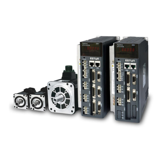
- Page 1 ETS Series AC Servo User's Manual (Version:V1.06)...
- Page 2 All rights reserved. No part of this publication may be reproduced, stored in a retrieval system, or transmitted, in any form, or by any means, mechanical, electronic, photocopying, recording, or otherwise, without the prior written permission of ESTUN. No patent liability is assumed with respect to the use of the information contained herein. - 1 -...
- Page 3 ETS Series AC Servo User's Manual About this manual This manual describes the following information required for designing and maintaining ETS series servo drives. •Specification of the servo drives and servomotors. •Procedures for installing the servo drives and servomotors.
-
Page 4: Safety Precautions
ETS Series AC Servo User's Manual Safety Precautions ■ Do not connect the servomotor directly to the local electrical network. Failure to observe this may result in damage to servomotor. ■ Do not plug or unplug connectors from servo drivewhen power is on. -
Page 5: Table Of Contents
ETS Series AC Servo User's Manual —Contents— About this manual ................................- 2 - Safety Precautions ................................- 3 - Chapter 1 ..................................- 7 - Checking Products and Parts Names ..........................- 7 - 1.1 Checking Products on Delivery ......................... - 7 - 1.1.1 Servomotor ............................ - Page 6 ETS Series AC Servo User's Manual Chapter 4 ..................................- 37 - Operation ..................................- 37 - 4.1 Trial Operation ..............................- 37 - 4.1.1 Trial Operation for Servomotor Without Load ..................- 39 - 4.1.2 Trial Operation for Servomotor without Load from Host Reference ............. - 41 - 4.1.3 I/O JOG control ............................
- Page 7 ETS Series AC Servo User's Manual 4.9.4 Machine Rigidity Setting for Online Autotuning ..................- 84 - 4.10 Internal Homing Function ..........................- 85 - Chapter 5 ..................................- 88 - Panel Operator ................................- 88 - 5.1 Basic Operation .............................. - 88 - 5.1.1 Functions on Panel Operator .......................
-
Page 8: Chapter 1
However, if a brake is installed on the servomotor, then it cannot be turned by hand. If any of the above items are faulty or incorrect, contact your ESTUN representative or the dealer from whom you purchased the products. - Page 9 ETS Series AC Servo User's Manual EMG– ESTUN Servomotor 【1+2】 【3】 【4】 【5】 【6】 【7】 EMG Model 【1+2】 【4】Encoder 【7】Option Rated Output Code Spec. Code Spec. Code Spec. 1.0kW Incremental Wire-saving Type: 2500P/R None Incremental encoder: 1048576P/R With oil seal Absolute encoder:...
- Page 10 ETS Series AC Servo User's Manual Appearance and Nameplate 1.1.2 Servo drive Servo Drive Appearanceand Nameplate - 9 -...
- Page 11 ETS Series AC Servo User's Manual Servo drive Model Designation ETS –10 10 A P C– CAN Communication ETS model servo drive CAN:CAN model B axis Rated Output Encoder Interface C: Wire-saving incremental encoder (2500P/R) A axis Rated Output...
-
Page 12: Servo Drive
ETS Series AC Servo User's Manual 1.2 Part Names 1.2.1 Servomotor Servomotor without gear and brake. Encoder Mounting hole Shell Output shaft Flange 1.2.2 Servo drive ETS two-axis servo drive Charge indicator Lights when the main circuit power supply is ON and stays lit as long as the main circuit power supply capacitor remains charged. - Page 13 ETS Series AC Servo User's Manual ETS three-axis servo drive Charge indicator Lights when the main circuit power supply is ON and stays lit as long as the main circuit power supply capacitor remains charged. Main circuit power supply terminals Connector for communication Used for main circuit power supply input.
-
Page 14: Servomotor
ETS Series AC Servo User's Manual Chapter 2 Installation 2.1 Servomotor Servomotor can be installed either horizontally or vertically. However, if the servomotor is installed incorrectly, the service life of the servomotor will be shortened or unexpected problems may occur. -
Page 15: Installation Alignment
ETS Series AC Servo User's Manual 2.1.3 Installation Alignment Align the shaft of the servomotor with that of the machinery shaft to be controlled. Then connect the two shafts with an elastic coupling. Install the servomotor so that alignment accurancy falls within the range shown below. -
Page 16: Cable Tension
When the servo motor is mounted to the client,please firmly secure the servo motor by the screws with backing ring as shown in the figure. 2.2 Servo Drive ETS series servo drive is a base-mounted type. Incorrect installation will cause problems. Always observe the installation instructions described below. 2.2.1 Storage When the servomotor is not being used, store it in an area with a temperature between -20℃... -
Page 17: Installation Orientation
ETS Series AC Servo User's Manual 2.2.3 Installation Orientation Install the servo drive perpendicular to the wall as shown in the figure. The servo drive must be oriented this way because it is designed to be cooled by natural convection or a cooling fan if required. Firmly secure the servo drive through two mounting holes. - Page 18 ETS Series AC Servo User's Manual between each individual servo drive and at least 50mm space above and below each one as well as shown in the figure above. Ensure the temperature inside the control panel is evenly distributed, and prevent the temperature around each servo drive from increasing excessively.
-
Page 19: Chapter 3
ETS Series AC Servo User's Manual Chapter 3 Wiring 3.1 Main Circuit Wiring Please observe the following instructions while wiring the main circuit. ! CAUTION · Do not bundle or run power and signal lines together in the same duct. Keep power andsignallines separated by at least 300 mm. -
Page 20: Typical Main Circuit Wiring Examples
ETS Series AC Servo User's Manual 3.1.1 Typical Main Circuit Wiring Examples ETS-101010APC-CAN/ETS-1010APC-CAN Three-phase +10% AC200~230 -15% 50/60Hz Molded-case Circuit Breaker Surge Protector Noise Filter Magnetic Contactor Surge suppressor A(1) Servo motor B(2) C(3) D(4) Incremental Wire-saving Encoder(2500P/R) Encoder... - Page 21 ETS Series AC Servo User's Manual ETS-101010APG-CAN/ETS-1010APG-CAN Three-phase +10% AC200~230 -15% 50/60Hz Molded-case Circuit Breaker Surge Protector Noise Filter Magnetic Contactor Surge suppressor A(1) Servo motor B(2) C(3) D(4) Serial Encoder CN2_A Encoder BAT+ BAT- PG5V PG0V Shield Be sure to prepare the end of...
-
Page 22: Names And Functions Of Main Circuit Terminals
ETS Series AC Servo User's Manual 3.1.2 Names and Functions of Main Circuit Terminals Terminal Name Functions Symbol Main circuit power supply L1,L2,L3 Three-phase 200~230VAC +10%~-15% (50/60Hz) input terminal Axis A servomotor U_A,V_A, connection Connect to the axis A servomotor. -
Page 23: I/O Signals
ETS Series AC Servo User's Manual 3.2 I/O Signals 3.2.1 Examples of I/O Signal Connections CN1_A P represent multi-twisted /PAO pair wire 2KΩ Power supply for open collector reference PL1 150Ω PULS PULS PG dividing /PULS ratio output /PBO Position reference 2KΩ... - Page 24 ETS Series AC Servo User's Manual I/O Signal Connector ( ) Terminal Layout 3.2.2 CN1_A/CN1_B/CN1_C Terminal No. Name Function 0:/COIN(/VCMP) 0:Positioning completion (speed agree detection) 1:/TGON 1:Running signal output 2:/S-RDY 2:Servo ready 3:/CLT 3:Torque limit output 4:/BK 4:Brake interlock output 5:PGC...
- Page 25 ETS Series AC Servo User's Manual Terminal No. Name Function PAO+ Phase-A signal PAO- 18,36 DGND DGND Shell Notes: 1.The list of CN1_A、CN1_B、CN1_C about I/O Signal Names and Functions are the same. 2.(*)The signals of CN1_A/B/C-1、2,CN1_A/B/C-5、6,CN1_A/B/C-7、8 can be modified by Pn511;...
-
Page 26: I/O Signal Names And Functions
ETS Series AC Servo User's Manual 3.2.3 I/O Signal Names and Functions Terminal Name Function Control power supply input for I/O signals: Provide the +24V DC power supply DICOM /S-ON Servo ON:Turns the servomotor on. It has deferent means depends on deferent /P-CON control mode. -
Page 27: Interface Circuit
ETS Series AC Servo User's Manual connector shell. 3.2.4 Interface Circuit This section shows examples of servo drive I/O signal connection to the host controller. ■Interface for input circuit The input circuit interface connects through a relay or open-collector transistor circuit.Select a low-current relay otherwise a faulty contact will result. -
Page 28: Wiring Encoders
ETS Series AC Servo User's Manual 3.3 Wiring Encoders 3.3.1 Connecting an Encoder(CN2_A/ CN2_B/ CN2_C) ETS-101010APC-CAN/ETS-1010APC-CAN Wire-saving Incremental Servodrive Encoder Host controller CN1_A/B/C CN2_A/B/C 1(A) Phase-A 1-34 2(B) 1-35 /PAO 3(C) 4(D) Phase-B 1-32 5(E) 1-33 /PBO 6(F) Phase-C... -
Page 29: Encoder Connector(Cn2_A/ Cn2_B/ Cn2_C) Terminal Layout
ETS Series AC Servo User's Manual 3.3.2 Encoder Connector(CN2_A/ CN2_B/ CN2_C) Terminal Layout ETS-101010APC-CAN/ETS-1010APC-CAN Terminal Name Function PG input phase A+ PG input phase A- PG input phase B+ PG input phase B- PG input phase C+ PG input phase C- PG5V 7、8、9... -
Page 30: Standard Wiring Example
ETS Series AC Servo User's Manual 3.5 Standard Wiring Example ETS-101010APC-CAN/ETS-1010APC-CAN +10% Three-phase AC200~230 50/60Hz -15% Molded-case Curcuit Breaker Surge Protector Noise Filter Magnetic Contactor A(1) Servo motor B(2) C(3) D(4) CN2_AWire-saving Encoder Encoder PG5V 7,8,9 PG0V 17,18,19 ETS Servo Drive... - Page 31 ETS Series AC Servo User's Manual CN1_A、CN1_B、CN1_C: CN1_A/B/C P represent multi-twisted /PAO pair wire 2KΩ Power supply for open collector reference PL1 150Ω PULS PULS PG dividing /PULS ratio output /PBO Position reference 2KΩ Power supply for open collector reference PL2 150Ω...
- Page 32 ETS Series AC Servo User's Manual ETS-101010APG-CAN/ETS-1010APG-CAN +10% Three-phase AC200~230 50/60Hz -15% Molded-case Curcuit Breaker Surge Protector Noise Filter Magnetic Contactor A(1) Servo motor B(2) C(3) D(4) CN2_A Serial Encoder Encoder BAT+ BAT- PG5V PG0V Shield ETS Servo Drive...
- Page 33 ETS Series AC Servo User's Manual CN1_A、CN1_B、CN1_C: CN1_A/B/C P represent multi-twisted /PAO pair wire 2KΩ Power supply for open collector reference PL1 150Ω PULS PULS PG dividing /PULS ratio output /PBO Position reference 2KΩ Power supply for open collector reference PL2 150Ω...
-
Page 34: Wiring For Noise Control
ETS Series AC Servo User's Manual 3.6 Wiring for Noise Control 3.6.1 Noise Control The servodrive uses high-speed switching elements in the main circuit. It may receive "switching noise"from these high-speed switching elements. To prevent malfunction due to noise, take the following actions: •... -
Page 35: Precautions On Connecting Noise Filter
ETS Series AC Servo User's Manual •When using a noise filter, follow the precautions in 3.6.2 Precautions on Connecting Noise Filter. (2) Correct Grounding Take the following grounding measures to prevent the servo drive from malfunctioning due to noise. ■ Grounding the Motor Frame If the servomotor is grounded via the machine, a switching noise current will flow from the servo drive main circuit through the servomotor stray capacitance. - Page 36 ETS Series AC Servo User's Manual Noise Noise Filter Filter Ground plate Ground plate Noise Noise Filter Filter Ground plate Ground plate Separate these circuits Separate the noise filter ground wire from the output lines. Do not accommodate the noise filter ground wire, output lines and other signal lines in the same duct or bundle them together.
- Page 37 ETS Series AC Servo User's Manual Control Panel Servodrive Noise Filter Servodrive Ground Ground plate - 36 -...
-
Page 38: Chapter 4
ETS Series AC Servo User's Manual Chapter 4 Operation 4.1 Trial Operation Make sure that all wiring has been completed prior to trial operation. Perform the following three types of trial operation in order. Instructions are given for speed control mode (standard setting) and position control mode. - Page 39 ETS Series AC Servo User's Manual Step Item Description Reference Install the servomotor and servo drive according to the installation Installation conditions. (Do not connect the servomotor to the machine because the servomotor will be operated first under the no-load condition for checking.) Connect the power supply circuit (L1, L2 and L3), servomotor wiring (U, V, W), I/O signal wiring (CN1_A/B/C), and encoder wiring (CN2_A/B/C).
-
Page 40: Trial Operation For Servomotor Without Load
ETS Series AC Servo User's Manual 4.1.1 Trial Operation for Servomotor Without Load ! CAUTION ·Release the coupling between the servomotor and the machine, and secure only the servomotor without a load. ·To prevent accidents, initially perform the trial operation for servomotor under no-load conditions (with all couplings and belts disconnected). - Page 41 ETS Series AC Servo User's Manual Step Description Check Method and Remarks Use the panel operator to operate the servomotor with utility function Fn002 (JOG Mode Operation)Check that the servomotor rotates in the forward direction by pressing the INC key, and reverse direction by pressing the DEC Panel Operator key.
-
Page 42: Trial Operation For Servomotor Without Load From Host Reference
ETS Series AC Servo User's Manual JOG Speed Speed Position Pn305 Setting Range Setting Unit Factory Setting Setting Validation 0~6000 Immediately Set the utility function Fn002 (JOG Mode Operation) to the reference value of servomotor speed. The servomotor can be operated using only the panel operator without reference from the host controller. - Page 43 ETS Series AC Servo User's Manual Step Description Check Method and Remarks Match the reference pulse form with the pulse output form Set the reference pulse form with Pn004.2. from the host controller. Set the reference unit and electronic gear ratio so that it Set the electronic gear ratio with Pn201(or coincides with the host controller setting.
-
Page 44: I/O Jog Control
ETS Series AC Servo User's Manual 4.1.3 I/O JOG control This function is available under all control mode, JOG speed is according to the value that set in the parameter Pn305; The operation is different from Fn002 and Modbus communication which have independent S-ON operation (Mode selection、S-ON for JOG operation). - Page 45 ETS Series AC Servo User's Manual step 1 operates normally. when an error occurs during operation. Perform trial operation with the servomotor connected Check that the trial operation is completed according to to the machine, following each section in 4.1.2 Trial the trial operation for servomotor without load.
-
Page 46: Trial Operation For Servomotor With Brakes
Check the servomotor operation and holding brake operation with the servomotor separated from the machine.If both operations are correct, connect the servomotor to the machine and perform trial operation. 4.2 Control Mode Selection The control modes supported by the ETS series servo drives are described below. Parameter Control Mode Speed Control (parameter reference) Controls servomotor speed using parameter reference. -
Page 47: Setting Common Basic Functions
ETS Series AC Servo User's Manual 4.3 Setting Common Basic Functions 4.3.1 Setting the Servo ON Signal This sets the servo ON signal (/S-ON) that determines whether the servomotor power is ON or OFF. (1)Servo ON signal(/S-ON) Connector Pin Type... -
Page 48: Switching The Servomotor Rotation Direction
ETS Series AC Servo User's Manual 4.3.2 Switching the Servomotor Rotation Direction The rotation direction of the servomotor can be switched without changing the reference pulse to the servo drive or the reference voltage polarity. This causes the rotation the servo motor shaft is rotating to change. The output signal polarity, such as the encoder pulse output and the analog monitor signal from the servo drive do not change. -
Page 49: Setting The Overtravel Limit Function
ETS Series AC Servo User's Manual 4.3.3 Setting the Overtravel Limit Function The overtravel limit function forces movable machine parts to stop if they exceed the allowable range of motion and turn ON a limit switch. (1)Connecting the overtravel signal To use the overtravel function, connect the following overtravel limit switch to the corresponding pin number of servo drive CN1_A/B/C connector correctly. - Page 50 ETS Series AC Servo User's Manual (2)Enabling/Disabling the Overtravel Signal A parameter can be set to disable the overtravel signal. If the parameter is set, there is no need to wire the overtravel input signal. Parameter Meaning b.□□0□ Inputs forward...
- Page 51 ETS Series AC Servo User's Manual ·After changing these parameters, turn OFF the main circuit and control power supplies, and then turn them ON again to enable the new settings. Servodrive Servomotor ·Stop by dynamic brake: Stops by using the dynamic brake (short circuiting its electrical circuit).
-
Page 52: Setting For Holding Brakes
ETS Series AC Servo User's Manual 4.3.4 Setting for Holding Brakes The holding brake is used when the servo drive controls a vertical axis. A servomotor with the brake option helps prevent movable parts from shifting due to gravity when power is removed from the servo drive.(Refer to 4.1.4 Trial Operation for Servomotor with Brakes.) - Page 53 ETS Series AC Servo User's Manual (2)Brake interlock output Type Signal Name Connector Pin Number Setting Meaning ON(Low level) Releases the brake. Output Must be allocated OFF(High level) Applies the brake. This output signal controls the brake and is used only for a servomotor with a brake. This output signal is not used with the factory setting.The output signal must be allocated by Pn511.
- Page 54 ETS Series AC Servo User's Manual (4)Setting the Brake ON/OFF Timing after the Servomotor Stops With the factory setting, the /BK signal is output at the same time as the servo is turned OFF. The servo OFF timing can be changed with a parameter.
-
Page 55: Absolute Encoders
ETS Series AC Servo User's Manual (5)Setting the Brake ON/OFF Timing When Servomotor Running The following parameters can be used to change the /BK signal output conditions when a stop reference is output during servomotor operation due to the servo OFF or an alarm occuring. -
Page 56: Selecting An Absolute Encoder
ETS Series AC Servo User's Manual 4.4.1 Selecting an Absolute Encoder An absolute encoder can also be used as an incremental encoder. Parameter Meaning Pn002 b.□0□□ Use the absolute encoder as an absolute encoder. (Factory setting) b.□1□□ Use the absolute encoder as an incremental encoder. -
Page 57: Handling Battery
In order for the absolute encoder to retain position data when the power is turned OFF, the data must be backed up by a battery. Please purchase the special cable and battery case mabe by Estun if an absolute encoder is used. Install the battary to the encoder cable:... -
Page 58: Replacing Battery
ETS Series AC Servo User's Manual 4.4.3 Replacing Battery The servo drive will generate an absolute encoder battery alarm (A.48) when the battery voltage drops below about 3.1V. Battery Replacement Procedure 1. Replace the battery with only the servo drive control power supply turned ON. -
Page 59: Soft Start
ETS Series AC Servo User's Manual 4.5.2 Soft Start The soft start function converts the stepwise speed reference inside the servo drive to a consistent rate of acceleration and deceleration. Pn310 can be used to select the soft start form: 0: Slope;... -
Page 60: S-Curve Risetime
ETS Series AC Servo User's Manual 4.5.4 S-curve Risetime S-curve Risetime Speed Pn309 Setting Range Setting Unit Factory Setting Setting Validation Immediately 0~10000 4.5.5 Encoder Signal Output Encoder feedback pulses processed inside the servo drive can be output externally. Type... - Page 61 ETS Series AC Servo User's Manual 90° Forward(CCW) Reverse(CW) 90° Phase A Phase A Phase B Phase B Pn001.0=1: 90° Forward(CCW) Reverse(CW) 90° Phase A Phase A Phase B Phase B If the servomotor is not equipped with an absolute encoder, the servomotor needs two full rotations before using the servo drive's Phase-C pulse output as the zero point reference.
-
Page 62: Speed Coincidence Output
ETS Series AC Servo User's Manual Pulse Dividing Ratio Setting PG Dividing Ratio Speed Position Pn200 Setting Range Setting Unit Factory Setting Setting Validation 1~2500 Puls 2500 After restart Set the number of pulses for PG output signals(PAO,/PAO,PBO,/PBO) externally from the servo drive. -
Page 63: Speed Control(Contact Reference)
ETS Series AC Servo User's Manual 4.5.7 Speed control(contact reference) The function of internally set speed selection allows speed control operation by externally selecting an input signal from among seven servomotor speed setting made in advance with parameters in the servo drive. The speed control operations within the three settings are valid. - Page 64 ETS Series AC Servo User's Manual Internal set speed 7 speed Pn322 Setting Range Setting Unit Factory Setting Setting Validation -6000~6000 Immediately (Note):The servomotor’s maximum speed will be used whenever a speed setting for the Pn316~Pn322 exceeds the maximum speed.
-
Page 65: Operating Using Position Control
ETS Series AC Servo User's Manual 4.6 Operating Using Position Control 4.6.1 Basic Setting in Position Control (1)Control mode selection Set the following parameters for position control using pulse trains. Parameter Meaning Pn005 H.□□1□ Control mode selection:position control(pulse train reference) - Page 66 ETS Series AC Servo User's Manual Forward Rotation Reverse Rotation PULS (CN1_A/B/C-25) SIGN (CN1_A/B/C-27) × 1 Internal processing × 2 Servomotor movement reference pulses. × 4 (3)Inverse PULS and SIGN reference 0□□□ Pn004 Do not inverse PULS reference and SIGN reference 1□□□...
-
Page 67: Setting The Clear Signal
ETS Series AC Servo User's Manual 4.6.2 Setting the Clear Signal (1)Setting the Clear Signal Type Sign Name Connector Pin Numbe Function Input /CLR CN_A/B/C-15 error counter clear When the /CLR signal is set to low level, clear error counter: ·The error counter inside the servo drive is set to“0”... - Page 68 ETS Series AC Servo User's Manual 16 Bit Electronic Gear Ratio (Denominator) Pn202 Setting Range Setting Unit Factory Setting Setting Validation — 1~65535 After restart 32 Bit Electronic Gear Ratio (Numerator,H) Pn705 Setting Range Setting Unit Factory Setting Setting Validation 1~9999...
- Page 69 ETS Series AC Servo User's Manual Calculate the electronic gear ratio. Use the electronic gear ratio equation to calculate the ratio (B/A). Set parameters. Set parameters using the calculated values. (4)Electronic Gear Ratio Setting Examples The following examples show electronic gear ratio settings for different load configurations.
- Page 70 ETS Series AC Servo User's Manual (5)Electronic Gear Ratio Equation Servomotor Pitch=P(mm/rev) Reference pulse Position Speed — loop loop Reference unit × 4 (P/rev)) (P/rev)): Encoder pulses P(mm/rev):Ball screw pitch :Deceleration ratio ...
-
Page 71: Smoothing
ETS Series AC Servo User's Manual 4.6.4 Smoothing A filter can be applied in the servo drive to a constant-frequency reference pulse. (1)Selecting a Position Reference Filter Parameter Description 0:1 -order filter Pn205 1:2 -order filter * After changing the parameter, turn OFF the power once and turn it ON again to enable the new setting. -
Page 72: Low Frequency Vibration Suppression
For the low rigidity load, low frequency vibration will occur continually at the front end of the load during fast acceleration or fast deceleration. The vibration may delay positioning time and affect the productive efficiency. The function of low frequency vibration suppression is embedded in ETS series servo drives by calculating the load position and compensating. - Page 73 ETS Series AC Servo User's Manual Position error counter ΔT f = 1 / ΔT Related Parameters Parameter Meaning 0:Low frequency vibration suppression function disabled H.□0□□ Pn006 1:Speed low frequency vibration suppression function enabled H.□1□□ 2: Position low frequency vibration suppression function enabled...
-
Page 74: Positioning Completion Output Signal
ETS Series AC Servo User's Manual 4.6.6 Positioning Completion Output Signal This signal indicates that servomotor movement has been completed during position control. Use the signal as an interlock to confirm that positioning has been completedat the host controller. Type... -
Page 75: Reference Pulse Inhibit Function(Inhibit)
ETS Series AC Servo User's Manual 4.6.7 Reference Pulse Inhibit Function(INHIBIT) (1)Description This function inhibits the servo drive from counting input pulses during position control. The servomotor remains locked (clamped) while pulses are inhibited. Servodrive Pn005.1 Pn005=H.□□1□ Reference pulse Error Counter Pn005=H.□□4□... -
Page 76: Position Control (Contact Reference)
ETS Series AC Servo User's Manual 4.6.8 Position Control (contact reference) Position control under contact reference (parameter Pn005.1=5). In this mode, servo drive can position with a single axes without a host controller. There are 16 position control points with each being able to set move distance, running speed, constants for position reference filter time, and the stop time when positioning completed. - Page 77 ETS Series AC Servo User's Manual Setting Para. No. Name and description Default range [0] Clear error pulse when S-0FF, not clear error pulse when overtravel. Pn004.1 [1] Not clear error pulse [2] Clear error pulse When S-OFF or over travel ■Looking for the reference point...
- Page 78 ETS Series AC Servo User's Manual Change steps by external /P-CON Change step and start mode signals. The signal will be valid when 0: Delay changing steps, the start signal is not drive output reaches the desired needed. Pn681.1 position. When input signal changes, 1: Change steps by /P-CON, start signal not needed.
-
Page 79: Limiting Torque
ETS Series AC Servo User's Manual 4.7 Limiting Torque The servo drive provides internal torque limit/external torque limitfor limiting output torque to protect the machine. 4.7.1 Internal Torque Limit Speed Position Maximum torque is always limited to the values set in the following parameters. -
Page 80: External Torque Limit
ETS Series AC Servo User's Manual 4.7.2 External Torque Limit This function allows the torque to be limited at specific times during machine operation, for example, during press stops and hold operations for robot workpieces. An input signal is used to enable the torque limits previously set in parameters. -
Page 81: Other Output Signals
ETS Series AC Servo User's Manual 4.8 Other Output Signals 4.8.1 Servo alarm output The following diagram shows the right way to connect the Alarm Output. Servo drive I/O Power supply +24V Optocoupler output ALM+ (Each output node) 50mA max Max.output voltage: 30V... - Page 82 ETS Series AC Servo User's Manual Pn511.0 SignalName Connector PinNumber Setting Meaning CN1_A/B/C-5/6 Servomotor is not OFF=H operating(Servomotor speed is below the setting in Pn503). ON=L Servo is ready. CN1_A/B/C-7/8 /S-RDY CN1_A/B/C-1/2 CN1_A/B/C-5/6 OFF=H Servo is not ready. Motor output torque under limit...
-
Page 83: Online Autotuning
ETS Series AC Servo User's Manual 4.9 Online Autotuning 4.9.1 Online Autotuning Online autotuning calculates the load moment of inertia during operation of the servo drive and sets parametersso that the servo gains are consistent with the machine rigidity. Online autotuning may not be effective in the following cases: •... -
Page 84: Setting Online Autotuning
ETS Series AC Servo User's Manual Start Operate with factor setting. (Set Pn100=1) Operation OK? Load moment of inertia varies? Continuous online autotuning (Pn100=1、2、3、4、5、6) Operation OK? Adjust the machine rigidity setting (Set at Pn101) Operation OK? Do not perform online autotuning. -
Page 85: Machine Rigidity Setting For Online Autotuning
ETS Series AC Servo User's Manual 1,4 = Load inertia without variation; 2,5 = Load inertia with little variation; 3,6=Load inertia with great variation — Pn101 Machine rigidity setting 0~15 Immediately Speed gain acceleration relationship during online autotuning — Pn128... -
Page 86: Internal Homing Function
The servomotor always needs to operate at a fixed position. This position is normally regarded as the zero position. When the host controller is turned on, the zero position adjustment is required before processing. This zero position will be regarded as the reference point. ESTUN servo drives can perform this function by the homing function. (1)Homing Mode Setting Para. - Page 87 ETS Series AC Servo User's Manual Signal Connector Pin Type Setting Meaning Name Number ON=↑(rising edge) Homing is enabled Must be allocated by Input SHOM Pn509,Pn510 OFF(not rising edge) Homing is disabled ON=H ORG is enabled Must be allocated by...
- Page 88 ETS Series AC Servo User's Manual Mechanical shaft Machine moves, return to search pulse C Motor slow down, reverse Begin to counter offset distance after the first C-pulse is produced when leaving zero posiion. Encoder C-pulse Rising edge SHOM After hitting the origin signal ORG, the motor will find C-pulse directly; the figure is shown as below:...
-
Page 89: Chapter 5
ETS Series AC Servo User's Manual Chapter 5 Panel Operator 5.1 Basic Operation 5.1.1 Functions on Panel Operator The panel operator is a built-in operator that consists of display section and keys located on the front panel of the servo drive. -
Page 90: Basic Mode Selection
ETS Series AC Servo User's Manual AXIS MODE INC DEC ENTER 5.1.3 Basic Mode Selection The basic modes include status display mode, parameter setting mode, monitor mode, and utility function mode. Each time the MODE key is pressed, the next mode in the sequence is selected. - Page 91 ETS Series AC Servo User's Manual Bit Data Code ① ② ③ ⑦ ④ ⑤ ⑥ Bit Data Display Speed/Torque Control Mode Position Control Mode Bit Data Description Bit Data Description Lit when the difference between the Lit if error between position reference...
-
Page 92: Operation In Parameter Setting Mode
ETS Series AC Servo User's Manual Codes Display Code Meaning Baseblock Servo OFF(servomotor power OFF) Servo ON(servomotor power ON) Forward Run Prohibited CN1_A/B/C_12(P-OT)is OFF. Reverse Run Prohibited CN1_A/B/C_13(N-OT)is OFF. Alarm Status Displays the alarm number. Press ENTER key to clear the present servo alarm. -
Page 93: Operation In Monitor Mode
ETS Series AC Servo User's Manual 5.1.6 Operation in Monitor Mode The monitor mode allows the reference values input into the servo drive, I/O signal status, and servo drive internal status to be monitored. ■Using the Monitor Mode The example below shows how to display the value (1500) stored in Un001. - Page 94 ETS Series AC Servo User's Manual ■List of Monitor Modes Contents of Monitor Mode Display Monitor Number Monitor Display Un000 Actual servomotor speed Unit: rpm Un001 Reserved Un002 Reserved Internal torque reference Unit:% Un003 (with respect to rated torque) Un004...
- Page 95 ETS Series AC Servo User's Manual Contents of Bit Display: MonitorNumber Display LED Number Content /SON(CN1_A/B/C-10) /P-CON(CN1_A/B/C-11) P-OT(CN1_A/B/C-12) N-OT(CN1_A/B/C-13) Un005 /ALM-RST(CN1_A/B/C-14) /CLR (CN1_A/B/C -15) /PCL(CN1_A/B/C-16) /NCL(CN1_A/B/C-17) Monitor Number Display LED Number Content (Not used) (Not used) (Not used) (Not used)...
-
Page 96: Operation In Utility Function Mode
ETS Series AC Servo User's Manual 5.2 Operation in Utility Function Mode In utility function mode, the panel operator can be used to run and adjust the servo drive and servomotor. The following table shows the parameters in the utility function mode. -
Page 97: Parameter Settings Initialization
ETS Series AC Servo User's Manual 5.2.2 Parameter Settings Initialization Follow the procedures below to execute the parameter settings initialization. 1.Press the MODE key to select the utility function mode. 2. Press the INC or DEC key to select the function number of parameter settings initialization. -
Page 98: Operation In Jog Mode
ETS Series AC Servo User's Manual 5.2.3 Operation in JOG Mode Follow the procedures below to operate the servomotor in JOG mode. 1. Press the MODE key to select the utility function mode. 2. Press the INC or DEC key to select the function number of JOG mode operation. -
Page 99: Offset-Adjustment Of Servomotor Current Detection Signal
ETS Series AC Servo User's Manual 5.2.4 Offset-adjustment of Servomotor Current Detection Signal Automatic servomotor current detection offset adjustment is performed at ESTUN before shipping. Basically, the user does not need to perform this adjustment. Perform this adjustment only if highly accurate adjustment is required for reducing torque ripple caused by current offset. - Page 100 ETS Series AC Servo User's Manual 4. Press the MODE key to switch between the phase U(o _ CuA) and phase V(1_ Cub) servomotor current detection offset adjustment. 5. Hold the ENTER key for one second to display the phase V offset amount.
-
Page 101: Software Version Display
ETS Series AC Servo User's Manual 5.2.5 Software Version Display Select Fn007 in utility function mode to check the current software version of the drive. 1. Press the MODE key to select the utility function mode. 2. Press the INC or DEC key to select the utility function number Fn007. -
Page 102: Parameters Copy
ETS Series AC Servo User's Manual Thus, the static inertia detection is complete. Note:Make sure that the servomotor completes at least 6 full revolutions in the CCW direction before detection. 5.2.8 Parameters Copy 1. Press the MODE key to select the utility function mode. -
Page 103: Chapter 6
MODBUS Communication 6.1 RS-485 Communication Wiring ETS series servo drives provide the MODBUS communication function with RS-485 interface, which can be used to easily set parameters or to perform monitoring operations and so on. The definitions of the servo drive communication connector terminals(CN3、CN4) are as follows. -
Page 104: Modbus Communication Related Parameters
ETS Series AC Servo User's Manual 6.2 MODBUS Communication Related Parameters Setting Parameter No. Description Control Mode Meaning Validation Pn700.0 MODBUS baud rate [0] 4800bps [1] 9600bps [2] 19200bps [3] 38400bps [4] 57600bps [5] 115200bps Pn700.1 Communication protocol selection [0] 7,N,2(MODBUS,ASCII)... -
Page 105: Modbus Communication Protocol
ETS Series AC Servo User's Manual 6.3 MODBUS Communication Protocol There are two modes for MODBUS communication: ASCII (American Standard Code for information interchange) mode and RTU (Remote Terminal Unit) mode. The next section describes the two communication modes. 6.3.1 Code Meaning ASCII Mode:... - Page 106 ETS Series AC Servo User's Manual 8,N,2(Modbus,ASCII / RTU) Start Stop Stop 8-data bits 11- bits character frame 8,E,1(Modbus,ASCII / RTU) Even Start Stop parity 8-data bits 11- bits character frame 8,O,1(Modbus,ASCII / RTU) Start Stop parity 8-data bits 11- bits character frame Communication protocol structure:...
- Page 107 ETS Series AC Servo User's Manual communication speed). ADR(communication address) Valid communication address:1 to 254 For example: communicate with the servo drive which address is 32(20 in hex) : ,‘0’=30 ASCII mode:ADR=‘2’,‘0’=>‘2’=32 RTU mode:ADR=20H CMD(command reference)and DATA(data) Data structure is determined by command code. Regular command code is shown as follows: Command code: 03H,read N words(word),N ≦...
- Page 108 ETS Series AC Servo User's Manual ASCII mode: Reference information: Response information: “:” “:” ‘0’ ‘0’ ‘1’ ‘1’ ‘0’ ‘0’ ‘6’ ‘6’ ‘0’ ‘0’ ‘0’ Data start address ‘0’ ‘7’ Data start address ‘7’ ‘0’ ‘0’ ‘0’ ‘0’ ‘0’ Data content ‘0’...
- Page 109 ETS Series AC Servo User's Manual For example: read 1 word from 01 servo address 0201 ‘:’ ‘0’ ‘1’ ‘0’ ‘3’ ‘0’ ‘2’ Data start address ‘0’ ‘1’ ‘0’ ‘0’ Data number ‘0’ (count as word) ‘1’ ‘F’ LRC checking ‘8’...
- Page 110 ETS Series AC Servo User's Manual ASCII mode: Communication is ended with (0DH) - [carriage return] and (0AH) - [new line]. RTU mode: When the time exceeds the sleep interval by at least 4 bytes transmission time while in the current communication speed, it means the communication is finished.
-
Page 111: Communication Error Disposal
ETS Series AC Servo User's Manual 6.3.2 Communication Error Disposal Problems that occur during communication are a result of the following: Data address is incorrect while reading/writing parameters. The data is not within the parameter setting range while writing. -
Page 112: Data Communication Address Of Servo State
ETS Series AC Servo User's Manual 6.3.3 Data Communication Address of Servo State The communication parameter addresses are shown in the following table: Communication data address(Hex) Meaning Description Operation Axis A Axis B Axis B Corresponding Read/write 0000~0348 2000~2348 4000~4348... - Page 113 ETS Series AC Servo User's Manual 01:Enable 1023 3023 5023 Write only JOG servo enabled 00:Disable 01:Forward rotation 1024 3024 5024 Write only JOG forward rotation 00:Stop 01:Reverse rotation 1025 3025 5025 Write only JOG reverse rotation 00:Stop Note: 1. Parameter area(axis A 0000~0348H、axis B 2000~2348H 、axis C 4000~4348H)...
-
Page 114: Chapter 7
ETS Series AC Servo User's Manual Chapter 7 Specifications and Characters 7.1 Servo drive Specifications and Models ETS-1010APC-CAN/ETS-101010APC-CAN Servo Drive Model ETS-1010APG-CAN/ETS-101010APG-CAN EMJ-A5A EMJ-01A EMJ-02A EMG-10A Applicable Servomotor Model EMJ-04A EMJ-08A EMJ-10A EML-10A Input Main Circuit Three-phase 200~230VAC +10% -15% (50/60Hz) - Page 115 ETS Series AC Servo User's Manual Signal allocations and positive/negative logic modifications: Servo ON (/S-ON) , P control ( /P-CON) , alarm reset ( /ALM-RST) , position error Function clear(/CLR) ,forward run prohibited(P-OT) ,reverse run prohibited(N-OT) , forward current limit(/P-CL) ,reverse current limit(/N-CL) and so on.
-
Page 116: Servo Drive Dimensional Drawings
ETS Series AC Servo User's Manual 7.2 Servo drive Dimensional Drawings - 115 -... -
Page 117: Parameter
ETS Series AC Servo User's Manual Appendix A Parameter A.1 Parameter List Parameter Setting Factory Setting Name Unit Range Setting Invalidation Binary Pn000.0:Servo ON Pn000.1:Forward rotation input signal prohibited(P-OT) — Pn000 0~1111 After restart Pn000.2:Reverse rotation input signal prohibited(N-OT) Pn000.3:Alarm output when... - Page 118 ETS Series AC Servo User's Manual Parameter Setting Factory Setting Name Unit Range Setting Invalidation Pn005.0:Torque feedforward mode Pn005.1:Control mode [0] Speed control(parameter reference) [1] Position control(pulse train) [2] Speedcontrol(contactreference) [3]Speed control(contact reference)←→ — Pn005 0~0x3361 0x0000 After restart position control(pulse train) [4] Position control(pulse train)←→...
- Page 119 ETS Series AC Servo User's Manual Parameter Setting Factory Setting Name Unit Range Setting Invalidation Pn107 2nd speed loop gain 1~4000 Immediately Pn108 2nd speed loop integral time constant 0.25ms 1~4096 Immediately Pn109 2nd position loop gain 0~1000 Immediately Pn110 2nd torque reference filter time constant 0.025ms...
- Page 120 ETS Series AC Servo User's Manual Parameter Setting Factory Setting Name Unit Range Setting Invalidation Pn200 PG divided ratio Puls After restart 1~16384 16384 — Pn201 1st electronic gear numerator 1~65535 After restart — Pn202 Electronic gear denominator 1~65535 After restart —...
- Page 121 ETS Series AC Servo User's Manual Parameter Setting Factory Setting Name Unit Range Setting Invalidation Pn500 Positioning error Puls 0~5000 Immediately Pn501 Coincidence difference 0~100 Immediately — — — — Pn502 Reserved Pn503 Rotation detection speed TGON 0~3000 Immediately Pn504...
- Page 122 ETS Series AC Servo User's Manual Parameter Setting Factory Setting Name Unit Range Setting Invalidation Pn664 Stop time 50ms 0~300 Immediately …… Pn679 Stop time 50ms 0~300 Immediately — — — — Pn680 Reserved Pn681.0:Single/cyclic, start/reference point selection — Pn681...
-
Page 123: Description Of Parameter Type
ETS Series AC Servo User's Manual Parameter Setting Factory Setting Name Unit Range Setting Invalidation — Pn710 32 bit 2nd electronic gear numerator (L) 0~9999 After restart Pn840.0:Encoder model selection 0x0003 — — Pn840 After restart Pn840.1:Reserved ~0x0F29 Pn840.2:Power level of Machine Pn840.3:Reserved... -
Page 124: Parameters In Detail
ETS Series AC Servo User's Manual A.3 Parameters in detail Parameter Setting Control Description Function and Meaning Validation Mode Pn000.0 Servo ON [0] External S-ON enabled. [1]External S-ON disabled. Servomotor excitation signal is turned ON automatically after S-RDY is output. - Page 125 ETS Series AC Servo User's Manual Parameter Setting Control Description Function and Meaning Validation Mode Pn203 Electronic gear numerator 2 Pn201 Pn201 Electronic gear numerator 1 Electronic gear numerator 1 PCON enabled PCON disabled PCON disabled Reference pulse t1,t2>1ms Time sequence when Pn002.0=0 or 1...
- Page 126 ETS Series AC Servo User's Manual Parameter Setting Control Description Function and Meaning Validation Mode when overtravel, then places it into coast (power OFF) mode. [4]Stops the servomotor by DB when servo OFF, stops the servomotor by plug braking when overtravel, then places it into zero clamp mode.
- Page 127 ETS Series AC Servo User's Manual Parameter Setting Control Description Function and Meaning Validation Mode control(INHIBIT) PCON:OFF Position control(pulse train reference);ON position control(INHIBIT) [5]Position control(contact reference) PCON: Used to change step PCL,NCL:Used to search reference point or start [6] Reserved Pn005.2 Out-of-tolerance alarm selection...
- Page 128 ETS Series AC Servo User's Manual Parameter Setting Control Description Function and Meaning Validation Mode Pn007.2:Reserved Pn007.3:Torque filter [0] Standard torque filter [1] New torque filter Pn009.0:Reserved Pn009.1:Reserved Pn009.2:Electronic gear selection Pn009 Binary After restart [0] 16 bit electronic gear [1] 32 bit electronic gear Pn009.3:Reserved...
- Page 129 ETS Series AC Servo User's Manual Parameter Setting Control Description Function and Meaning Validation Mode filter time constant mechanical vibration, but incorrect setting will result to mechanical vibration.Unit:0.025ms Load inertia Setting value=(load inertia/rotor inertia) Pn106 Immediately P,S percentage Unit: %...
- Page 130 ETS Series AC Servo User's Manual Parameter Setting Control Description Function and Meaning Validation Mode 0:Torque reference percentage 1:Value of offset counter P/PI switching Pn116 After restart P,S 2:Value of acceleration speed setting condition 3:Value of speed setting 4:Fixed PI Torque switching Threshold of torque to switch PI control to P control.
- Page 131 ETS Series AC Servo User's Manual Parameter Setting Control Description Function and Meaning Validation Mode Analog encoder output orthogonal difference pulses. PG divided The meaning of this value is the number of analog Pn200 After restart P,S ratio encoder output orthogonal difference pulses per one servomotor rotation.
- Page 132 ETS Series AC Servo User's Manual Parameter Setting Control Description Function and Meaning Validation Mode operation. Soft start acceleration The time for trapeziform acceleration to accelerate to 1000rpm. Pn306 Immediately time Unit: ms The time for trapeziform deceleration to decelerate to...
- Page 133 ETS Series AC Servo User's Manual Parameter Setting Control Description Function and Meaning Validation Mode Pn408 Notch filter 1 depth Immediately P,S Notch filter 1 depth up and response will be Notch filter 2 lagged after notch filter Pn409 Immediately P,S...
- Page 134 ETS Series AC Servo User's Manual Parameter Setting Control Description Function and Meaning Validation Mode and then /BK signal is created after delaying the parameter setting time. Basic waiting flow: Standard setting: /BK output (braking action) and servo-OFF are at the same time.
- Page 135 ETS Series AC Servo User's Manual Parameter Setting Control Description Function and Meaning Validation Mode CN1_A/B/C_7 , Pn511.0 corresponding port CN1_A/B/C_8 CN1_A/B/C_1 , Pn511.1 corresponding port CN1_A/B/C_2 CN1_A/B/C_5 , Pn511.2 corresponding port CN1_A/B/C_6 Corresponding signal of each data is shown as...
- Page 136 ETS Series AC Servo User's Manual Parameter Setting Control Description Function and Meaning Validation Mode — — — Pn519 Reserved Position complete Pn520 Immediately Position complete time time — — — Pn521 Reserved — — — Pn522 Reserved — —...
- Page 137 ETS Series AC Servo User's Manual Parameter Setting Control Description Function and Meaning Validation Mode JPOS15 Point to The speed of JPOS15 point to point control Pn647 Immediately point speed control Unit:rpm JPOS0 1st order filter time of JPOS0 point to point control can...
- Page 138 ETS Series AC Servo User's Manual Parameter Setting Control Description Function and Meaning Validation Mode control (contact reference); Speed of finding reference point (Hitting the origin signal ORG) in position homing control. Leave travel switch speed in position control (contact reference);...
- Page 139 ETS Series AC Servo User's Manual Parameter Setting Control Description Function and Meaning Validation Mode [5] 115200bps Pn700.1 MODBUS protocol selection [0] 7,N,2(MODBUS,ASCII) [1] 7,E,1(MODBUS,ASCII) [2] 7,O,1(MODBUS,ASCII) [3] 8,N,2(MODBUS,ASCII) [4] 8,E,1(MODBUS,ASCII) [5] 8,O,1(MODBUS,ASCII) [6] 8,N,2(MODBUS,RTU) [7] 8,E,1(MODBUS,RTU) [8] 8,O,1(MODBUS,RTU) Pn700.2 Reserved Pn700.3 Reserved...
- Page 140 ETS Series AC Servo User's Manual Parameter Setting Control Description Function and Meaning Validation Mode [5] Reserved [6] Wire-saving incremental encoder [7] Reserved [8] 20 bit incremental encoder [9] 20 bit absolute encoder Pn840.1 Motor designing sequence [0] EM□-□□□□A [1] EM□-□□□□B Pn840.2 Power level of Machine...
- Page 141 ETS Series AC Servo User's Manual Appendix B Alarm Display Alarm Alarm Alarm Name Meaning Display Output ╳ A.01 Parameter breakdown The checksum results of parameters are abnormal. The servomotor speed is excessively high and the ╳ A.03 Overspeed servomotor is out of control.
- Page 142 ETS Series AC Servo User's Manual Alarm Alarm Alarm Name Meaning Display Output The parameter setting of servo drive does not match the ╳ A.43 Servo drive type error servomotor. Absolute encoder multiturn ╳ A.45 Absolute encoder multiturn information is faulty.
Need help?
Do you have a question about the ETS Series and is the answer not in the manual?
Questions and answers