Table of Contents
Advertisement
Quick Links
Advertisement
Table of Contents

Related Manuals for Estun ATRIO MC404-Z


Summary of Contents for Estun ATRIO MC404-Z
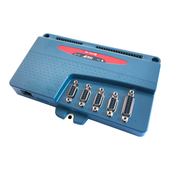
- Page 1 IP RESET MICRO SD CARD ETHERNET PORT CHASSIS PLATE AND LED INDICATORS EARTH CONNECTION POWER AND 16 DIGITAL INPUTS PANEL MOUNT 8 DIGITAL OUTPUTS (NPN) STEPPER AXES (0-2) D-TYPE CONNECTOR STEPPER / ENCODER AXIS (3) D-TYPE CONNECTOR 15 WAY D-TYPE AUXILIARY CONNECTOR QUICK START GUIDE MC404-Z P855...
- Page 2 SAFETY WARNING During the installation or use of control systems, users of Trio products must ensure that there is no possibility of injury to any person or damage to machinery. Control systems, especially during installation, can malfunction or behave unexpectedly. Bearing this in mind, users must ensure that even in the event of a malfunction or unexpected behaviour, the safety of an operator or programmer is never compromised.
- Page 3 POWER / DIGITAL OUTPUT CONNECTOR (NPN) DIGITAL INPUT CONNECTOR (NPN / PNP) This is a 12 way 3.5mm pitch connector. Pins 1 to 4 are used to provide the 24 Volt power to the MC404-Z. A 24V dc, Pin Function Function Class 2 transformer or power source must be provided as this Common Bank 0...
- Page 4 STEPPER AXIS CONNECTOR (0-2) 9 way D-type Axis connectors Pin Number Axis 0 to 2 (Stepper) Step+ Step- Dir+ Dir- 0V Step Enable+ Enable- RS422 Line Driver STEPPER OUT / ENCODER IN AXIS CONNECTOR (3) 9 way D-type Axis connector Pin Number Axis 3 (Stepper OR Encoder) S+/A+...
- Page 5 AUXILIARY CONNECTOR 15 way Auxiliary D-Sub Connector Pin Number Function Note RS232 Transmit Serial Port #1 RS485 Data In A Rx+ Serial Port #2 RS485 Data Out Y Tx+ Serial Port #2 AIN (Analogue In) 0V to 10V max, 12 bits WDOG+ Positive Solid State Output CAN HIGH...
- Page 6 GROUNDING AND SHIELDING Good quality screened cables should be used for the auxiliary port. The serial ports and CANbus port are not galvanically isolated, therefore the 0V return MUST be connected to all peripheral devices. In addition, bond together the 0V (24V return) terminals of all system components so as to minimise current flowing in the serial cables.
- Page 7 LED STATUS INDICATORS Display at start-up Display with WDOG on Display Error green - ON red - OFF green - ON red - FLASHING green - ON red - ON CHASSIS MOUNTING DIMENSIONS (LOOKING FROM REAR) M4 screws should be used in 3 places to mount the MC404-Z to an unpainted earthed metal panel. Best EMC performance is obtained when all 3 screws are attached to the metal back panel.
- Page 8 176.5 mm 28mm UK | USA | CHINA | INDIA WWW.TRIOMOTION.COM T H E M O T I O N S P E C I A L I S T CAD data Drawings to aid packaging and mounting are available in various formats from the Trio web site. Products should be wired by qualified persons.
Need help?
Do you have a question about the ATRIO MC404-Z and is the answer not in the manual?
Questions and answers