
Related Manuals for TechNexion FLEX-IMX8M-Mini


Summary of Contents for TechNexion FLEX-IMX8M-Mini
- Page 1 FLEX-IMX8M-Mini SYSTEM ON MODULE PRODUCT MANUAL (WITH NXP i.MX8M Mini SoC) VER. 1.00 January 31, 2020...
- Page 2 FLEX-IMX8M-Mini HARDWARE MANUAL – VER 1.00 – JAN 31 2020 REVISION HISTORY Revision Date Originator Notes November 6, 2019 TechNexion Preliminary 1.00 January 31, 2020 TechNexion General Public Release Page 2 of 48...
-
Page 3: Table Of Contents
FLEX-IMX8M-Mini HARDWARE MANUAL – VER 1.00 – JAN 31 2020 TABLE OF CONTENTS 1. Introduction ............................5 1.1. General Introduction ........................5 2. FLEX-IMX8M-Mini Product Overview ....................5 2.1. FLEX-IMX8M-Mini System-on-Module Overview ................. 5 2.2. Block Diagram ..........................6 2.3. Dimensional Drawing........................6 2.4. - Page 4 Figure 5 – FLEX-IMX8M-Mini Bottom View .................... 7 Figure 6 – NXP i.MX8M-Mini Processor Blocks..................9 Figure 7 – FLEX-IMX8M-Mini Wi-Fi Module and Antenna Connector Location ........12 Figure 8 – FLEX-IMX8M-Mini JTAG Connector..................17 Figure 9 – FLEX-IMX8M-Mini Board-to-Board Connectors ..............18...
-
Page 5: Introduction
The FLEX-IMX8M-Mini is a high performance highly integrated FLEX Compute Module designed around the NXP i.MX8M Mini Quad core ARM Cortex-A53 + Cortex-M4 applications processor. The FLEX-IMX8M-Mini provides an ideal building block that easily integrates with a wide range of target markets requiring compact, cost effective with low power consumption. -
Page 6: Block Diagram
FLEX-IMX8M-Mini HARDWARE MANUAL – VER 1.00 – JAN 31 2020 2.2. Block Diagram Figure 2 – FLEX-IMX8-Mini System-on-Module Block Diagram Overview 2.3. Dimensional Drawing The FLEX-IMX8-Mini System-on-Module is an ultra-compact module in FLEX form factor. Figure 3 – FLEX-IMX8-Mini System-on-Module Dimensions... -
Page 7: Component Location
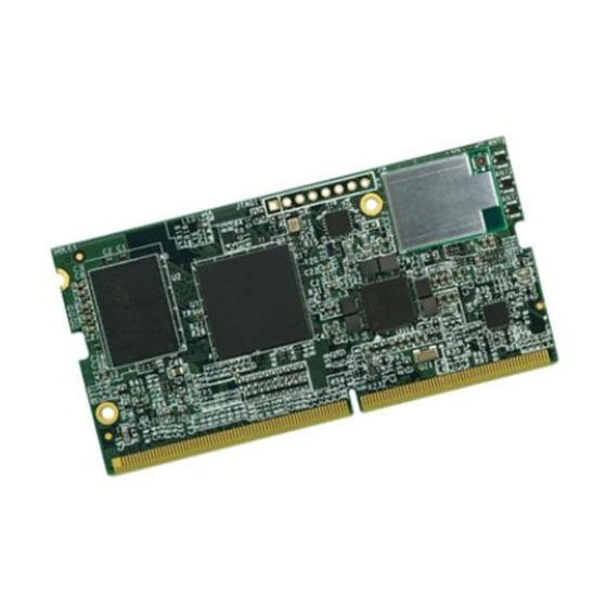
FLEX-IMX8M-Mini HARDWARE MANUAL – VER 1.00 – JAN 31 2020 2.4. Component Location Figure 4 – FLEX-IMX8M-Mini Top View Figure 5 – FLEX-IMX8M-Mini Bottom View Description Description NXP i.MX8M Mini Processor Wi-Fi/Bluetooth Module (optional) Memory IC eMMC Storage IC ROHM BD71847 PMIC... -
Page 8: Core Components
FLEX-IMX8M-Mini HARDWARE MANUAL – VER 1.00 – JAN 31 2020 3. Core Components 3.1. NXP i.MX8M Mini ARM Cortex-A53 + Cortex-M4 Processor The i.MX 8M Mini is NXP’s first embedded multicore applications processor built using advanced 14LPC FinFET process technology, providing more speed and improved power efficiency. With commercial and industrial level qualification and backed by NXP’s product longevity program, the i.MX... -
Page 9: Figure 6 - Nxp I.mx8M-Mini Processor Blocks
FLEX-IMX8M-Mini HARDWARE MANUAL – VER 1.00 – JAN 31 2020 Figure 6 – NXP i.MX8M-Mini Processor Blocks Page 9 of 48... -
Page 10: Power Management Ic (Rohm Bd71847)
WDOG_B PMIC and i.MX8M-Mini To perform a hard-reset of the FLEX-IMX8M-Mini an external circuit (for example a button or external watchdog IC) can be integrated on the carrier board by using PIN 238. Table 3 – PMIC Hard Reset Signal Description... -
Page 11: Memory
FLEX-IMX8M-Mini HARDWARE MANUAL – VER 1.00 – JAN 31 2020 3.3. Memory The FLEX-IMX8M-Mini integrates Low Power Double Data Rate IV (LPDDR4) Synchronous DRAM is connected over a 32-Bit dual channel configuration. (16 bit per channel). The following memory chip manufacturers have been validated and tested on the FLEX-IMX8M-Mini Compute Module: •... -
Page 12: Wi-Fi/Bluetooth
FLEX-IMX8M-Mini HARDWARE MANUAL – VER 1.00 – JAN 31 2020 3.5. Wi-Fi/Bluetooth The FLEX-IMX8M-Mini has an optional pre-certified high-performance TechNexion PIXI-9377 dual band 2.4/5Ghz Wi-Fi / Bluetooth 5 Qualcomm Atheros QCA9377 based module on board. The PIXI-9377 Wi-Fi / Bluetooth module is designed to operate with a single antenna for Wi-Fi and Bluetooth by using the MHF4 connector. -
Page 13: Table 5 - Wi-Fi Signal Description
FLEX-IMX8M-Mini HARDWARE MANUAL – VER 1.00 – JAN 31 2020 Table 5 – Wi-Fi Signal Description i.MX8M PAD NAME Signal Description BALL SD1_DATA0 USDHC1_DATA0 MMC/SDIO Data bit 0 SD1_DATA1 USDHC1_DATA1 MMC/SDIO Data bit 1 SD1_DATA2 USDHC1_DATA2 MMC/SDIO Data bit 2... -
Page 14: Table 6 - Bluetooth Signal Description
FLEX-IMX8M-Mini HARDWARE MANUAL – VER 1.00 – JAN 31 2020 Table 6 – Bluetooth Signal Description i.MX8M PAD NAME Signal Description BALL UART1_TXD UART1_TXD Bluetooth UART Serial Input. Serial data input for the HCI UART Interface UART1_RXD UART1_RXD Bluetooth UART Serial Output. Serial data output for the HCI UART Interface. -
Page 15: Atheros Ar8035 Gigabit Lan
FLEX-IMX8M-Mini HARDWARE MANUAL – VER 1.00 – JAN 31 2020 3.6. Atheros AR8035 Gigabit LAN The FLEX-IMX8M-Mini connects the i.MX8M Mini processor RGMII interface to the Atheros AR8035 gigabit Ethernet chip. The AR8035 supports IEEE 802.3az EEE standard (Energy Efficient Ethernet) and Atheros proprietary SmartEEE. -
Page 16: Table 7 - Gigabit Ethernet Interconnect Between I.mx8M Mini And Ar8035
FLEX-IMX8M-Mini HARDWARE MANUAL – VER 1.00 – JAN 31 2020 Table 7 - Gigabit Ethernet interconnect between i.MX8M Mini and AR8035 AR8035 PAD NAME Signal Description BALL AG24 ENET_TXC ETH_TXCLK RGMII transmit clock AG26 ENET_TD0 ETH_TXD0 RGMII transmit data 0... -
Page 17: Jtag
FLEX-IMX8M-Mini HARDWARE MANUAL – VER 1.00 – JAN 31 2020 3.7. JTAG The FLEX-IMX8M-Mini has an on module JTAG Controller that provides debug and test control with maximum security. The test access port is designed to support features compatible with the IEEE standard 1149.1 v2001 (JTAG). -
Page 18: Flex Compute Module Pin Assignment
FLEX-IMX8M-Mini HARDWARE MANUAL – VER 1.00 – JAN 31 2020 4. FLEX Compute Module Pin Assignment Figure 9 – FLEX-IMX8M-Mini Board-to-Board Connectors Table 9 – FLEX Compute Module Pin Assignment CPU PAD NAME Signal Description BALL System input power VSYS (4.75 to 5.25V) - Page 19 FLEX-IMX8M-Mini HARDWARE MANUAL – VER 1.00 – JAN 31 2020 Interface (MDI) differential pair 2 negative signal Ground Ground Gigabit Ethernet Media Dependent AR8035 pin 12 GBE_MDI1+ Interface (MDI) differential pair 1 positive signal Gigabit Ethernet Media Dependent AR8035 pin 18...
- Page 20 FLEX-IMX8M-Mini HARDWARE MANUAL – VER 1.00 – JAN 31 2020 Ground Not Connected MIPI Display Serial MIPI_DSI_D2_N MIPI_DSI_D2_N Interface data pair 2 negative signal Not Connected MIPI Display Serial MIPI_DSI_D2_P MIPI_DSI_D2_P Interface data pair 2 positive signal Ground Ground Not Connected...
- Page 21 FLEX-IMX8M-Mini HARDWARE MANUAL – VER 1.00 – JAN 31 2020 MIPI Camera Serial MIPI_CSI_CLK_ MIPI_CSI_CLK_P Interface clock pair positive signal Not Connected Ground Ground MIPI Camera Serial MIPI_CSI_D0_N MIPI_CSI_D0_N Interface data pair 0 negative signal Not Connected MIPI Camera Serial...
- Page 22 FLEX-IMX8M-Mini HARDWARE MANUAL – VER 1.00 – JAN 31 2020 Not Connected Ground Not Connected Not Connected General Purpose AF14 GPIO1_IO01 PWM1_OUT Input Output with PWM control Not Connected General Purpose GPIO1_IO13 PWM2_OUT Input Output with PWM control Ground General Purpose...
- Page 23 FLEX-IMX8M-Mini HARDWARE MANUAL – VER 1.00 – JAN 31 2020 PCI Express Receive PCIE_RXN_P PCIE_RXN_P input differential pair positive signal Not Connected Not Connected Ground Not Connected Not Connected Ground Not Connected Not Connected Ground Not Connected Not Connected Ground...
- Page 24 FLEX-IMX8M-Mini HARDWARE MANUAL – VER 1.00 – JAN 31 2020 Ground Not Connected Not Connected Not Connected Not Connected Not Connected Ground Not Connected Not Connected Not Connected Not Connected Ground Ground I2C1_SCL I2C1_SCL I2C bus clock line Universal Serial Bus...
- Page 25 FLEX-IMX8M-Mini HARDWARE MANUAL – VER 1.00 – JAN 31 2020 Universal Asynchronous ECSPI1_SCLK UART3_RXD Receive Transmit receive data signal Integrated Interchip AC22 SAI2_TXD0 SAI2_TXD Sound (I2S) channel transmit data line Universal Asynchronous ECSPI1_SS0 UART3_RTS_B Receive Transmit request to send signal...
- Page 26 FLEX-IMX8M-Mini HARDWARE MANUAL – VER 1.00 – JAN 31 2020 Receive Transmit transmit data signal General Purpose AC15 SAI5_RXC GPIO3_IO20 Input Output Universal Asynchronous UART2_RXD UART2_RXD Receive Transmit receive data signal General Purpose NAND_DATA00 GPIO3_IO06 Input Output Universal Asynchronous UART4_TXD...
-
Page 27: Flex-Imx8M-Mini External Interfaces
FLEX-IMX8M-Mini HARDWARE MANUAL – VER 1.00 – JAN 31 2020 5. FLEX-IMX8M-Mini External Interfaces 5.1. Ethernet The FLEX-IMX8M-Mini provides a 10/100/1000-Mbit/s MAC ethernet interface which, implements layer 3 network acceleration functions. These functions are designed to accelerate the processing of various common networking protocols, such as IP, TCP, UDP, and ICMP, providing wire speed services to client applications. -
Page 28: Mipi Display
FLEX-IMX8M-Mini HARDWARE MANUAL – VER 1.00 – JAN 31 2020 5.2. MIPI Display The Mobile Industry Processor Interface (MIPI) Display Serial Interface (DSI) controller is a flexible, high-performance, and easy-to-use digital core that implements all protocol functions defined in the MIPI DSI Specification. -
Page 29: Table 11 - Mipi Display Signal Description
FLEX-IMX8M-Mini HARDWARE MANUAL – VER 1.00 – JAN 31 2020 Table 11 - MIPI Display Signal Description CPU PAD NAME Signal Description BALL MIPI Display Serial MIPI_DSI_D0_N MIPI_DSI_D0_N Interface data pair 0 negative signal MIPI Display Serial MIPI_DSI_D0_P MIPI_DSI_D0_P Interface data pair 0... -
Page 30: Mipi Camera
FLEX-IMX8M-Mini HARDWARE MANUAL – VER 1.00 – JAN 31 2020 5.3. MIPI Camera This section introduces the MIPI CSI-2 RX subsystem with the CSI-2 RX PHY and host controller. This subsystem handles the sensor/image input and process for all the input imaging devices. -
Page 31: Table 12 - Mipi Camera Control Signals
FLEX-IMX8M-Mini HARDWARE MANUAL – VER 1.00 – JAN 31 2020 Table 12 - MIPI Camera Control Signals CPU PAD NAME Signal Description BALL MIPI Camera Serial MIPI_CSI_CLK_ MIPI_CSI_CLK_N Interface clock pair negative signal MIPI Camera Serial MIPI_CSI_CLK_ MIPI_CSI_CLK_P Interface clock pair... -
Page 32: Audio Interface
FLEX-IMX8M-Mini HARDWARE MANUAL – VER 1.00 – JAN 31 2020 5.4. Audio Interface The FLEX-IMX8M-Mini provides multiple I S (or I S) interfaces that support fullduplex serial interfaces with frame synchronization such as I2S, AC97, TDM, and codec/DSP interfaces. The I S Interface supports the following features: •... -
Page 33: Table 13 - I2S-1 Audio Signal Description
FLEX-IMX8M-Mini HARDWARE MANUAL – VER 1.00 – JAN 31 2020 Table 13 - I2S-1 Audio Signal Description CPU PAD NAME Signal Description BALL Integrated Interchip SAI3_RXD SAI3_RXD Sound (I2S) channel receive data line Integrated Interchip Sound (I2S) channel SAI3_TXFS SAI3_TXFS... -
Page 34: Pci Express
FLEX-IMX8M-Mini HARDWARE MANUAL – VER 1.00 – JAN 31 2020 5.5. PCI Express This block provides information regarding PCIe PHY and its features. PCIe PHY supports 6.0 Gbps data rate and complies to PCI Express base specification 2.1. The functions that are performed by the transceiver include serializing the 8B/10B encoded data for transmission, de-serializing received code groups, and word alignment. -
Page 35: Universal Serial Bus (Usb) Interface
FLEX-IMX8M-Mini HARDWARE MANUAL – VER 1.00 – JAN 31 2020 5.6. Universal Serial Bus (USB) Interface The FLEX-IMX8M-Mini incorporates a single USB Host controller and an additional USB Host/OTG controller. Each of the USB controllers provides the following main features: USB 2.0 Host/OTG Controller... -
Page 36: Table 17 - Usb Otg Signal Description
FLEX-IMX8M-Mini HARDWARE MANUAL – VER 1.00 – JAN 31 2020 Table 17 - USB OTG Signal Description CPU PAD NAME Signal Description BALL Universal Serial Bus USB1_DN USB1_DN differential pair negative signal Universal Serial Bus USB1_DP USB1_DP differential pair positive signal... -
Page 37: Sdio/Mmc Interface
FLEX-IMX8M-Mini HARDWARE MANUAL – VER 1.00 – JAN 31 2020 5.7. SDIO/MMC Interface The FLEX-IMX8M-Mini features a MMC / SD / SDIO host interfaces connected to the NXP i.MX8M Mini integrated “Ultra Secured Digital Host Controller” (uSDHC). The following main features are supported by uSDHC: •... -
Page 38: Universal Asynchronous Receiver/Transmitter (Uart) Interface
FLEX-IMX8M-Mini HARDWARE MANUAL – VER 1.00 – JAN 31 2020 5.8. Universal Asynchronous Receiver/Transmitter (UART) Interface The FLEX-IMX8M-Mini Universal Asynchronous Receiver/Transmitter (UART) provides serial communication capability with external devices through a level converter. The UART includes the following features: •... -
Page 39: Table 19 - Uart3 Signal Description
FLEX-IMX8M-Mini HARDWARE MANUAL – VER 1.00 – JAN 31 2020 Table 19 – UART3 Signal Description CPU PAD NAME Signal Description BALL Universal Asynchronous ECSPI1_MOSI UART3_TXD Receive Transmit transmit data signal Universal Asynchronous ECSPI1_SCLK UART3_RXD Receive Transmit receive data signal... -
Page 40: Serial Peripheral Interface (Spi)
FLEX-IMX8M-Mini HARDWARE MANUAL – VER 1.00 – JAN 31 2020 5.9. Serial Peripheral Interface (SPI) The FLEX-IMX8M-Mini has an onboard SPI interface that can operate in either master or SPI slave mode. The SPI Interface includes the following features: •... -
Page 41: I 2 C Bus
FLEX-IMX8M-Mini HARDWARE MANUAL – VER 1.00 – JAN 31 2020 5.10. I C Bus The FLEX-IMX8M-Mini incorporates several I C interfaces. I C is a two-wire, bidirectional serial bus that provides a simple, efficient method of data exchange, Minimizing the interconnection between devices. -
Page 42: General Purpose Input / Output (Gpio)
5.11. General Purpose Input / Output (GPIO) The FLEX-IMX8M-Mini has 10 dedicated GPIO pins at 3.3V. Many of the other pins used on the FLEX Compute Module can be put in GPIO module however doing so might break scalability with other FLEX Compute Modules. -
Page 43: Pulse Width Modulation (Pwm)
FLEX-IMX8M-Mini HARDWARE MANUAL – VER 1.00 – JAN 31 2020 5.12. Pulse Width Modulation (PWM) The Pulse Width Modulation (PWM) has a 16-bit counter, and is optimized to generate sound from stored sample audio images and it can also generate tones. It uses 16-bit resolution and a 4 x 16 data FIFO. -
Page 44: Manufacturing And Boot Control
FLEX-IMX8M-Mini HARDWARE MANUAL – VER 1.00 – JAN 31 2020 5.13. Manufacturing and Boot Control The FLEX-IMX8M-Mini has a number of pins to override the default boot media present on the FLEX- IMX8M-Mini Compute Module or enable debug serial loader functionality. -
Page 45: Input Power Requirements
+/- 50mV 5.14.1. Reference and Output Power The FLEX-IMX8M-Mini is a versatile system on module that can be incorporated in an embedded system where the carrier board will have additional requirements for 3.3V. For this purpose the FLEX-IMX8M-Mini integrates a 3.3V reference voltage pin and an additional 3.3V power output. -
Page 46: Ordering Information
The FLEX-IMX8M-Mini is available in a number of standard configurations. Custom tailored versions with other memory configuration, de-population of interfaces or extended and industrial temperature options are available upon request. Standard part numbers can be easily found on the FLEX-IMX8M-Mini product page on the TechNexion corporate homepage. 6.2. Custom Part Number Rule The FLEX-IMX8M-Mini can be ordered in custom tailored configuration to meet special application requirements and conditions according to the following custom part number creation rules. -
Page 47: Important Notice
Information published by TechNexion regarding third-party products or services does not constitute a license from TechNexion to use such products or services or a warranty or endorsement thereof. Use of such information may require a license from a third party under the patents or other intellectual property of the third party, or a license from TechNexion under the patents or other intellectual property of TechNexion. -
Page 48: Disclaimer
To the extent permitted by law no liability (including liability to any person by reason of negligence) will be accepted by TechNexion Ltd., its subsidiaries or employees for any direct or indirect loss or damage caused by omissions from or inaccuracies in this document.
Need help?
Do you have a question about the FLEX-IMX8M-Mini and is the answer not in the manual?
Questions and answers