Table of Contents
Advertisement
Quick Links
Advertisement
Table of Contents

Related Manuals for TechNexion EDM1-IMX6PLUS


Summary of Contents for TechNexion EDM1-IMX6PLUS
- Page 1 EDM1-IMX6PLUS VER. 1.00 November 16, 2016...
- Page 2 EDM1-IMX6PLUS HARDWARE MANUAL – VER 1.00 – NOV 16 2016 REVISION HISTORY Revision Date Originator Notes 1.00 November 16, 2016 TechNexion Initial Public Release Page 2 of 83...
-
Page 3: Table Of Contents
EDM1-IMX6PLUS HARDWARE MANUAL – VER 1.00 – NOV 16 2016 TABLE OF CONTENTS 1. Introduction ............................... 7 1.1. General Introduction ........................... 7 1.2. General Care and Maintenance ......................8 1.3. Block Diagram ..........................10 1.4. EDM Compatibility ..........................11 1.5. Dimensional Drawing........................12 1.6. - Page 4 EDM1-IMX6PLUS HARDWARE MANUAL – VER 1.00 – NOV 16 2016 3.12. Universal Asynchronous Receiver/Transmitter (UART) Interface ..........53 3.13. Serial Peripheral Interface (SPI) ..................... 55 3.14. I C Bus ............................57 3.14.1. Display and System Management Purpose I C Bus ............... 57 3.14.2.
- Page 5 EDM1-IMX6PLUS HARDWARE MANUAL – VER 1.00 – NOV 16 2016 LIST OF TABLES Table 1 - EDM Compatibility Overview ....................... 11 Table 2 - PMIC Signal Description ......................18 Table 3 - eMMC Signal Description ......................20 Table 4 - NAND Signal Description ......................22 Table 5 - WiFi Signal Description ........................
- Page 6 Figure 14 - Input Power sequence for AT based configurations ..............63 Figure 15 - Input Power sequence for ATX based configurations .............. 64 Figure 16 - EDM1-IMX6PLUS Optional Power Connector Location............65 Figure 17 - EDM1-IMX6PLUS with mounted Molex 43650-0200 Connector ..........65 Page 6 of 83...
-
Page 7: Introduction
The EDM1-IMX6PLUS System-on-Module is typically being used as building blocks for portable and stationary embedded systems. The core CPU and support circuits, including DRAM, booth flash, power sequencing, CPU power supplies, Gigabit Ethernet and display interfaces are concentrated on the module. -
Page 8: General Care And Maintenance
EDM1-IMX6PLUS HARDWARE MANUAL – VER 1.00 – NOV 16 2016 1.2. General Care and Maintenance Your device is a product of superior design and craftsmanship and should be treated with care. The following suggestions will help you. Keep the device dry. Precipitation, humidity, and all types of liquids or moisture can contain minerals that will corrode electronic circuits. - Page 9 EDM1-IMX6PLUS HARDWARE MANUAL – VER 1.00 – NOV 16 2016 Federal Communications Commission (FCC) Unintentional emitter per FCC Part 15 This device has been tested and found to comply with the limits for a Class B digital device, pursuant to Part 15 of the FCC rules. These limits are designed to provide reasonable protection against harmful interference in a residential installation.
-
Page 10: Block Diagram
EDM1-IMX6PLUS HARDWARE MANUAL – VER 1.00 – NOV 16 2016 1.3. Block Diagram Figure 1 - EDM1-IMX6PLUS Block Diagram Page 10 of 83... -
Page 11: Edm Compatibility
EDM1-IMX6PLUS HARDWARE MANUAL – VER 1.00 – NOV 16 2016 1.4. EDM Compatibility The EDM1-IMX6PLUS is fully compatible with the EDM Type 1 Standard specifications. For additional details, please refer to the “EDM Standard Specifications”. Figure 2 – EDM Type 1 Compatibility Chart... -
Page 12: Dimensional Drawing
EDM1-IMX6PLUS HARDWARE MANUAL – VER 1.00 – NOV 16 2016 1.5. Dimensional Drawing The EDM1-IMX6PLUS is an EDM Type 1 Compact Form Factor System-on-Module and follows the EDM Standard Specifications in regards of dimensions and mounting options. 2D and 3D files can be obtained from the www.technexion.com... -
Page 13: Component Location
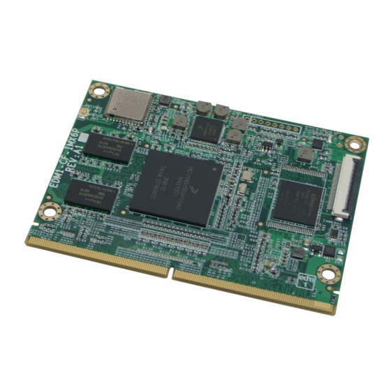
EDM1-IMX6PLUS HARDWARE MANUAL – VER 1.00 – NOV 16 2016 1.6. Component Location Figure 4 - EDM1-IMX6PLUS Top view Item Description Item Description NXP i.MX6 Processor MIPI Camera / Display Connector MMPF0100 Power Management IC WiFi / BT Module NAND Flash / eMMC (co-layout) -
Page 14: Core Components
EDM1-IMX6PLUS HARDWARE MANUAL – VER 1.00 – NOV 16 2016 2. Core Components 2.1. NXP i.MX6 Cortex-A9 Multi-core Processor The NXP i.MX6 processor is an implementation of the Single/Dual/Quad/Quadplus ARM Cortex™-A9 core, which operates at frequencies up to 1.2 GHz. The i.MX6 provides a variety of interfaces and supports the following main features: ... -
Page 15: Figure 7 - Nxp I.mx6 Processor Scalability Overview (Solo/Duallite/Dual/Quad/Quadplus)
EDM1-IMX6PLUS HARDWARE MANUAL – VER 1.00 – NOV 16 2016 Figure 7 – NXP i.MX6 Processor Scalability Overview (Solo/Duallite/Dual/Quad/QuadPlus) Page 15 of 83... -
Page 16: I.mx6 Memory Interfaces
EDM1-IMX6PLUS HARDWARE MANUAL – VER 1.00 – NOV 16 2016 2.1.1. i.MX6 Memory Interfaces The memory system consists of the following components: Level 1 Cache—32 KB Instruction, 32 KB Data cache per core Level 2 Cache—Unified instruction and data (1 MByte) ... -
Page 17: I.mx6 Video And Graphics Subsystems
EDM1-IMX6PLUS HARDWARE MANUAL – VER 1.00 – NOV 16 2016 2.1.3. i.MX6 Video and Graphics Subsystems The EDM1-IMX6PLUS video graphics subsystem consists of the following i.MX6 sub-blocks. VPU: A multi-standard high performance video codec engine supporting encode/decode operations of the following: Decoding: H.264 BP/CBP/MP/HP, VC-1 SP/MP/AP, MPEG-4 SP/ASP, H.263 P0/P3,... -
Page 18: Power Management Ic (Mmpf0100)
The EDM1-IMX6PLUS has on onboard NXP MMPF0100 power management integrated circuit (PMIC) that features a configurable architecture supporting the numerous outputs with various current ratings as well as programmable voltage and sequencing required by the components on the EDM1-IMX6PLUS module. -
Page 19: Memory
EDM1-IMX6PLUS HARDWARE MANUAL – VER 1.00 – NOV 16 2016 2.2. Memory The EDM1-IMX6PLUS integrates Double Data Rate III (DDR3) Synchronous DRAM in either a single (32 bit) or a dual (64 bit) channel configuration. The following memory chips have been validated and tested on the EDM1-IMX6PLUS System-on- Module: ... -
Page 20: Emmc Storage
EDM1-IMX6PLUS HARDWARE MANUAL – VER 1.00 – NOV 16 2016 2.3. eMMC Storage The EDM1-IMX6PLUS can be ordered with onboard eMMC storage in different configurations and capacity. The onboard eMMC device is connected on the SD3 pins of the i.MX6 processor in a 8 bit width configuration. -
Page 21: Figure 8 - Emmc Schematics
EDM1-IMX6PLUS HARDWARE MANUAL – VER 1.00 – NOV 16 2016 Figure 8 - eMMC Schematics Page 21 of 83... -
Page 22: Nand Flash Storage
EDM1-IMX6PLUS HARDWARE MANUAL – VER 1.00 – NOV 16 2016 2.4. NAND Flash Storage The EDM1-IMX6PLUS can be ordered with onboard NAND Flash storage in different configurations and capacity. The following NAND Flash chips have been validated and tested on the EDM1-IMX6PLUS System-on- Module: ... -
Page 23: Figure 9 - Nand Ic Schematics
EDM1-IMX6PLUS HARDWARE MANUAL – VER 1.00 – NOV 16 2016 Figure 9 - NAND IC Schematics Page 23 of 83... -
Page 24: Wifi/Bluetooth Sip Module
EDM1-IMX6PLUS HARDWARE MANUAL – VER 1.00 – NOV 16 2016 2.5. WiFi/Bluetooth SIP Module The EDM1-IMX6PLUS can be ordered with an optional onboard WiFI/Bluetooth SIP module. The WiFi / Bluetooth SiP module is a small sized BGA mounted module. The small size & low profile physical design make it easier for system design to enable high performance wireless connectivity without space constrain. -
Page 25: Table 5 - Wifi Signal Description
EDM1-IMX6PLUS HARDWARE MANUAL – VER 1.00 – NOV 16 2016 Table 5 - WiFi Signal Description i.MX6 PAD NAME Signal Description BALL SD2_DAT0 SD2_DATA_0 MMC/SDIO Data bit 0 SD2_DAT1 SD2_DATA_1 MMC/SDIO Data bit 1 SD2_DAT2 SD2_DATA_2 MMC/SDIO Data bit 2... -
Page 26: Table 7 - Bluetooth Signal Description
EDM1-IMX6PLUS HARDWARE MANUAL – VER 1.00 – NOV 16 2016 Table 7 - Bluetooth Signal Description i.MX6 PAD NAME Signal Description BALL EIM_D24 UART3_TXD Bluetooth UART Serial Input. Serial data input for the HCI UART Interface EIM_D25 UART3_RXD Bluetooth UART Serial Output. Serial data output for the HCI UART Interface. -
Page 27: Figure 11 - Wifi / Bt Schematics
EDM1-IMX6PLUS HARDWARE MANUAL – VER 1.00 – NOV 16 2016 Figure 11 - WiFi / BT Schematics Page 27 of 83... -
Page 28: Atheros Ar8035 Gigabit Lan
EDM1-IMX6PLUS HARDWARE MANUAL – VER 1.00 – NOV 16 2016 2.6. Atheros AR8035 Gigabit LAN The EDM1-IMX6Plus connects the i.MX6 processor RGMII interface to the Atheros AR8035 gigabit Ethernet chip. The AR8035 supports IEEE 802.3az EEE standard (Energy Efficient Ethernet) and Atheros proprietary SmartEEE. -
Page 29: Table 8 - Gigabit Ethernet Interconnect Between I.mx6 And Ar8035
EDM1-IMX6PLUS HARDWARE MANUAL – VER 1.00 – NOV 16 2016 Table 8 - Gigabit Ethernet interconnect between i.MX6 and AR8035 i.MX6 PAD NAME Signal AR8035 Description BALL RGMII_TXC ETH_TXCLK RGMII transmit clock RGMII_TD0 ETH_TXD0 RGMII transmit data 0 RGMII_TD1 ETH_TXD1... -
Page 30: Gigabit Ethernet Magnetics
EDM1-IMX6PLUS HARDWARE MANUAL – VER 1.00 – NOV 16 2016 2.6.1. Gigabit Ethernet Magnetics A Gigabit Ethernet coupling transformer either discrete or integrated inside a RJ45 jack should be integrated on the EDM carrier board. The following table is a selection of compatible Ethernet PHY’s available in the market that has been validated with the EDM1-IMX6PLUS. -
Page 31: Figure 12 - Gigabit Ethernet Schematics
EDM1-IMX6PLUS HARDWARE MANUAL – VER 1.00 – NOV 16 2016 Figure 12 - Gigabit Ethernet Schematics Page 31 of 83... -
Page 32: Mipi Camera And Display Connector
EDM1-IMX6PLUS HARDWARE MANUAL – VER 1.00 – NOV 16 2016 2.7 MIPI Camera and Display Connector The EDM1-IMX6PLUS expansion FPC connector carries the MIPI Serial Interface camera and display signals. CAMERA 2.7.1 MIPI Camera The MIPI CSI-2 Host Controller supports the following features: ... -
Page 33: Mipi Display
EDM1-IMX6PLUS HARDWARE MANUAL – VER 1.00 – NOV 16 2016 2.7.2 MIPI Display The MIPI DSI Host Controller supports the following features: IPU SIDE (input): Compliant with MIPI Alliance Specification for Display Serial Interface (DSI), Version 1.01.00 - 21 February 2008 ... - Page 34 EDM1-IMX6PLUS HARDWARE MANUAL – VER 1.00 – NOV 16 2016 Pin # i.MX6 PAD NAME Signal Description BALL MIPI Camera Serial Interface CSI_D2M CSI_DATA2_M data pair 2 negative signal Ground MIPI Camera Serial Interface CSI_D3P CSI_DATA3_P data pair 3 positive signal...
-
Page 35: Jtag Connector
EDM1-IMX6PLUS HARDWARE MANUAL – VER 1.00 – NOV 16 2016 2.8 JTAG Connector The EDM1-IMX6PLUS JTAG interface is derived from the i.MX6 processor integrated SJC module. The SJC module implements and manages the daisy-chained topology consisting of its’ own TAP and those of the SDMA, and the ARM Debug Access Port (DAP). -
Page 36: Edm Type 1 Connector Interfaces
3. EDM Type 1 Connector Interfaces 3.1 Gigabit Ethernet The EDM1-IMX6PLUS gigabit Ethernet Media Access Controller (MAC) is designed to support 10/100/1000 Mbps Ethernet/IEEE 802.3 networks. More information can be found in chapter 2.6. Atheros AR8035 Gigabit LAN of this hardware manual... -
Page 37: Lvds Interface
EDM1-IMX6PLUS HARDWARE MANUAL – VER 1.00 – NOV 16 2016 3.2. LVDS Interface The EDM1-IMX6PLUS is equipped with single LVDS Display interfaces. The LVDS Display Bridge (LDB) connects the IPU (Image Processing Unit) to an External LVDS Display Interface. The purpose of the LDB is to support flow of synchronous RGB data from the IPU to external display devices through LVDS interface. -
Page 38: Table 13 - Lvds Signal Description
EDM1-IMX6PLUS HARDWARE MANUAL – VER 1.00 – NOV 16 2016 Table 13 - LVDS Signal Description i.MX6 PAD NAME Signal Description BALL LVDS primary channel E3_9 LVDS0_TX0_N LVDS0_DATA0_N differential pair 0 negative signal LVDS primary channel E3_10 LVDS0_TX0_P LVDS0_DATA0_P differential pair 0 positive... -
Page 39: Hdmi (High Definition Multi-Media Interface)
EDM1-IMX6PLUS HARDWARE MANUAL – VER 1.00 – NOV 16 2016 3.3. HDMI (High Definition Multi-Media Interface) The HDMI interface available with EDM1-IMX6PLUS is based on the “HDMI transmitter” & “HDMI 3D Tx PHY” integrated into the i.MX6 processor. The “HDMI transmitter” combines video/display data from the IPU, Audio data from i.MX6 memory &... -
Page 40: Digital Display Sub-System (Dss) Or Ttl Interface
EDM1-IMX6PLUS HARDWARE MANUAL – VER 1.00 – NOV 16 2016 3.4. Digital Display Sub-System (DSS) or TTL Interface The Parallel Display interface of EDM1-IMX6PLUS is derived directly from the DI0 port of the IPU, effectively bypassing all the i.MX6 integrated display bridges. -
Page 41: Table 16 - Ttl Display Signal Description
EDM1-IMX6PLUS HARDWARE MANUAL – VER 1.00 – NOV 16 2016 Table 16 - TTL Display Signal Description i.MX6 PAD NAME Signal Description BALL DISP0_DAT0 IPU1_DISP0_DATA00 LCD Pixel Data bit 0 DISP0_DAT1 IPU1_DISP1_DATA01 LCD Pixel Data bit 1 DISP0_DAT2 IPU1_DISP1_DATA02 LCD Pixel Data bit 2... -
Page 42: Audio Interface
EDM1-IMX6PLUS HARDWARE MANUAL – VER 1.00 – NOV 16 2016 3.5. Audio Interface The EDM1-IMX6PLUS incorporates two I S / AUDMUX signals, one S/P DIF interface and can as well provide surround audio over the HDMI data signals. The AUDMUX provides flexible, programmable routing of the serial interfaces (SSI1 or SSI2) to and from off-chip devices. -
Page 43: Table 17 - Primary I
Secondary Integrated GPIO_0 CCM_CLKO1 Interchip Sound (I S) channel master clock signal NOTE: On EDM1-IMX6PLUS System-on-Modules that feature WiFi / Bluetooth functionality. The Secondary I S is routed to the onboard WiFi chip. Page 43 of 83... -
Page 44: S/P Dif Audio
Dolby Digital or DTS. The EDM1-IMX6PLUS features an S/P DIF interface allowing EDM module to transmit digital audio data. The S/PDIF interface is implemented by means of the i.MX6 integrated S/P DIF transceiver. -
Page 45: Pci Express
EDM1-IMX6PLUS HARDWARE MANUAL – VER 1.00 – NOV 16 2016 3.6. PCI Express The EDM1-IMX6PLUS is equipped with a single lane PCI Express interface, implemented in the i.MX6 processor. The PCI Express interface complies with PCIe specification Gen 2.0 and supports the PCI Express 1.1/2.0 standards. -
Page 46: Serial Ata Interface
EDM1-IMX6PLUS HARDWARE MANUAL – VER 1.00 – NOV 16 2016 3.7. Serial ATA Interface The EDM-IMX6PLUS incorporates a single SATA-II port implemented with the NXP i.MX6 integrated SATA controller and PHY. The interface supports the following main features: The SATA block fully complies with AHCI specification version 1.10 and partially complies with AHCI specification version 1.3 (FIS-based switching is currently not supported). -
Page 47: Universal Serial Bus (Usb) Interface
EDM1-IMX6PLUS HARDWARE MANUAL – VER 1.00 – NOV 16 2016 3.8. Universal Serial Bus (USB) Interface The EDM-IMX6PLUS incorporates a single USB Host controller and an additional USB Host/OTG controller. Each of the USB controllers provides the following main features: USB 2.0 Host/OTG Controller... -
Page 48: Table 22 - Usb Host Signal Description
EDM1-IMX6PLUS HARDWARE MANUAL – VER 1.00 – NOV 16 2016 Table 22 - USB Host Signal Description i.MX6 PAD NAME Signal Description BALL Universal Serial Bus carrier GPIO_17 GPIO7_IO12 board hub reset pin Over current detect input pin EIM_D30 USB_H1_OC... -
Page 49: Sdio/Mmc Interface
EDM1-IMX6PLUS HARDWARE MANUAL – VER 1.00 – NOV 16 2016 3.9. SDIO/MMC Interface The EDM1-IMX6PLUS features a MMC / SD / SDIO host interfaces connected to the NXP i.MX6 integrated “Ultra Secured Digital Host Controller” (uSDHC). The following main features are supported by uSDHC: ... -
Page 50: General Purpose Memory Controller Bus (Local Bus)
EDM1-IMX6PLUS HARDWARE MANUAL – VER 1.00 – NOV 16 2016 3.10. General Purpose Memory Controller Bus (Local Bus) The EDM1-IMX6PLUS features a general-purpose media interface which is connected to the NXP i.MX6 GPMI controller. The general-purpose media interface has several features to efficiently support NAND: ... -
Page 51: Table 25 - Gpmc / Local Bus Signal Description
EDM1-IMX6PLUS HARDWARE MANUAL – VER 1.00 – NOV 16 2016 Table 25 - GPMC / Local Bus Signal Description i.MX6 PAD NAME Signal Description BALL NANDF_CS0 NAND_CE0_B GPMC Chip Select bit A NANDF_CS1 NAND_CE1_B GPMC Chip Select bit B NANDF_CS2... -
Page 52: Can Bus Interface Signals
EDM1-IMX6PLUS HARDWARE MANUAL – VER 1.00 – NOV 16 2016 3.11. CAN BUS Interface signals The EDM1-IMX6PLUS features two CAN bus interfaces. The CAN bus interfaces are implemented with the i.MX6 on chip “Flexible Controller Area Network” (FlexCAN) communication modules. -
Page 53: Universal Asynchronous Receiver/Transmitter (Uart) Interface
EDM1-IMX6PLUS HARDWARE MANUAL – VER 1.00 – NOV 16 2016 3.12. Universal Asynchronous Receiver/Transmitter (UART) Interface The EDM1-IMX6PLUS makes 2 UART ports available on the EDM connector and utilizes an additional UART on the module to connect to the WiFi/Bluetooth module. -
Page 54: Table 29 - Secondary Uart Signal Description
NOTE: UART3 is not listed in this section. This interface is connected from the i.MX6 processor towards the WiFi/Bluetooth interface present on EDM1-IMX6PLUS and can be found in the WiFi/Bluetooth section of this manual. Page 54 of 83... -
Page 55: Serial Peripheral Interface (Spi)
EDM1-IMX6PLUS HARDWARE MANUAL – VER 1.00 – NOV 16 2016 3.13. Serial Peripheral Interface (SPI) The EDM1-IMX6PLUS features two Enhanced Configurable SPI ports, which are derived from the i.MX6 processor, integrated ECSPI IPs. The following main features are supported: ... -
Page 56: Table 31 - Secondary Spi Channel Signal Description
EDM1-IMX6PLUS HARDWARE MANUAL – VER 1.00 – NOV 16 2016 Table 31 - Secondary SPI Channel Signal Description i.MX6 PAD NAME Signal Description BALL Serial Peripheral Interface EIM_D18 ECSPI1_MOSI secondary channel master output slave input signal Serial Peripheral Interface EIM_D17... -
Page 57: I 2 C Bus
EDM1-IMX6PLUS HARDWARE MANUAL – VER 1.00 – NOV 16 2016 3.14. I C Bus The EDM1-IMX6PLUS I C interfaces are implemented with the i.MX6 integrated I C controller. There are two general purpose I C interfaces and one I C interface dedicated towards display and system management functions. -
Page 58: General Purpose I C Bus
EDM1-IMX6PLUS HARDWARE MANUAL – VER 1.00 – NOV 16 2016 3.14.2. General Purpose I C Bus The general purpose I C interfaces are both independent and have no reserved addresses or devices on the EDM1-IMX6PLUS. Table 33 – Primary General Purpose I C Bus Signal Description i.MX6... -
Page 59: General Purpose Input/Output (Gpio)
EDM1-IMX6PLUS HARDWARE MANUAL – VER 1.00 – NOV 16 2016 3.15. General Purpose Input/Output (GPIO) The EDM Standard stipulates 10 dedicated GPIO pins. Many of the EDM1-IMX6PLUS can be put in GPIO mode. Using the additional pins in GPIO mode however might break upgradability to other EDM modules. -
Page 60: Manufacturing And Boot Control
Pins for manufacturing and EIM_DA12 SRC_BOOT_CFG12 validation purposes The EDM1-IMX6PLUS can boot from the following devices that are present on the carrier board. Table 37 - EDM MNF Boot Configuration Option Overview SATA SD Cardslot eMMC on Carrier board N.C. -
Page 61: Table 38 - Edm-Mnf-Boot Configuration For Edm1-Fairy
EDM1-IMX6PLUS HARDWARE MANUAL – VER 1.00 – NOV 16 2016 When using EDM1-IMX6PLUS on the TechNexion EDM1-FAIRY evaluation carrier board. You can simply configure the EDM-MNF-BOOT PCB that comes with the EDM1-FAIRY-START evaluation kit as follow: Table 38 - EDM-MNF-BOOT Configuration for EDM1-FAIRY... -
Page 62: Input Power Requirements
±50 mV 3.17.1. Power Management Signals The EDM1-IMX6PLUS has the following set of signals to control the system power states such as the power-on and reset conditions. This enables the system designer to implement a fully ACPI compliant system supporting system states. The minimum hardware requirements for an ACPI compliant system are an EDM module supporting ACPI, ATX conforming power supply and a power button. -
Page 63: Power Sequencing For At Based Configurations
EDM1-IMX6PLUS HARDWARE MANUAL – VER 1.00 – NOV 16 2016 3.17.2. Power Sequencing for AT based configurations EDM1-IMX6PLUS input power sequencing requirements for AT based configurations are as follow: If a backup RealTime Clock (RTC) is required in the host system. We recommend to design an RTC circuit on the EDM carrier board. -
Page 64: Power Sequencing For Atx Based Configurations
EDM1-IMX6PLUS HARDWARE MANUAL – VER 1.00 – NOV 16 2016 3.17.3. Power Sequencing for ATX based configurations EDM1-IMX6PLUS input power sequencing requirements for ATX based configurations are as follow: If a backup RealTime Clock (RTC) is required in the host system. We recommend to design an RTC circuit on the EDM carrier board. -
Page 65: Edm1-Imx6Plus Power Option Without Carrier Board
EDM1-IMX6PLUS HARDWARE MANUAL – VER 1.00 – NOV 16 2016 3.17.4. EDM1-IMX6PLUS Power Option without Carrier Board The EDM1-IMX6PLUS provides support to be powered without a carrier board by mounting a power connector that provides +5V to the System-on-Module directly. -
Page 66: Edm Connector Pin Assignment
EDM1-IMX6PLUS HARDWARE MANUAL – VER 1.00 – NOV 16 2016 4. EDM Connector Pin Assignment The EDM1-IMX6PLUS EDM connector 314 pin assignment is listed in the table below. CPU PAD Signal Description BALL NAME Standby Power Supply 5VDC E1_1 5VSB 5VSB ±... - Page 67 EDM1-IMX6PLUS HARDWARE MANUAL – VER 1.00 – NOV 16 2016 i.MX6 PAD NAME Signal Description BALL Gigabit Ethernet Media AR8035 Dependent Interface (MDI) E4_2 GBE_MDI0+ pin 9 differential pair 0 positive signal Gigabit Ethernet Media AR8035 Dependent Interface (MDI) E3_3...
- Page 68 EDM1-IMX6PLUS HARDWARE MANUAL – VER 1.00 – NOV 16 2016 i.MX6 PAD NAME Signal Description BALL LVDS primary channel LVDS0_TX1_P LVDS0_DATA1_P differential pair 1 positive signal Ground Ground DISP0_DAT2 IPU1_DISP1_DATA02 LCD Pixel Data bit 2 LVDS primary channel LVDS0_TX2_N LVDS0_DATA2_N...
- Page 69 EDM1-IMX6PLUS HARDWARE MANUAL – VER 1.00 – NOV 16 2016 i.MX6 PAD NAME Signal Description BALL DISP0_DAT13 IPU1_DISP0_DATA13 LCD Pixel Data bit 13 Display ID DDC clock line used for LVDS flat panel EIM_D21 I2C1_SCL detection. If not used this can...
- Page 70 EDM1-IMX6PLUS HARDWARE MANUAL – VER 1.00 – NOV 16 2016 i.MX6 PAD NAME Signal Description BALL Display ID DDC data line used for HDMI detection. If EIM_D21 I2C1_SCL not used this can be assigned to General Purpose I C bus...
- Page 71 EDM1-IMX6PLUS HARDWARE MANUAL – VER 1.00 – NOV 16 2016 i.MX6 PAD NAME Signal Description BALL Ground NANDF_RB0 NAND_READY_B External indication of wait Not Connected NANDF_WP_B NAND_WP_B GPMC Write Protect / Enable Not Connected GPMC Lower Byte Enable. NANDF_CLE NAND_CLE...
- Page 72 EDM1-IMX6PLUS HARDWARE MANUAL – VER 1.00 – NOV 16 2016 i.MX6 PAD NAME Signal Description BALL Universal Serial Bus carrier GPIO_17 GPIO7_IO12 board hub reset pin Not Connected Over current detect input pin GPIO_9 GPIO1_IO09 to monitor USB power over...
- Page 73 EDM1-IMX6PLUS HARDWARE MANUAL – VER 1.00 – NOV 16 2016 i.MX6 PAD NAME Signal Description BALL Universal Serial Bus USB_H1_DN USB_H1_DN differential pair negative signal NANDF_D1 NAND_DATA01 GPMC data bit 1 Universal Serial Bus USB_H1_DP USB_H1_DP differential pair positive signal...
- Page 74 EDM1-IMX6PLUS HARDWARE MANUAL – VER 1.00 – NOV 16 2016 i.MX6 PAD NAME Signal Description BALL Ground SD1_CMD SD1_CMD MMC/SDIO Command SD1_CLK SD1_CLK MMC/SDIO Clock CSI0_DAT8 GPIO5_IO26 MMC/SDIO Write Protect CSI0_MCLK GPIO5_IO19 MMC/SDIO LED SD1_DAT1 SD1_DATA1 MMC/SDIO Data bit 1...
- Page 75 EDM1-IMX6PLUS HARDWARE MANUAL – VER 1.00 – NOV 16 2016 i.MX6 PAD NAME Signal Description BALL Universal Asynchronous SD4_DAT6 UART2_CTS_B Receive Transmit secondary channel clear to send signal GPIO_5 I2C3_SCL C bus clock line Universal Asynchronous SD4_DAT7 UART2_TX_DATA Receive Transmit secondary...
- Page 76 EDM1-IMX6PLUS HARDWARE MANUAL – VER 1.00 – NOV 16 2016 i.MX6 PAD NAME Signal Description BALL SD3_RST GPIO7_IO08 General Purpose Input Output Ground Ground Pins for manufacturing and EIM_DA13 SRC_BOOT_CFG13 validation purposes Not Connected Pins for manufacturing and EIM_DA14 SRC_BOOT_CFG14...
-
Page 77: Edm Pinmux Overview
EDM1-IMX6PLUS HARDWARE MANUAL – VER 1.00 – NOV 16 2016 5. EDM Pinmux Overview Many signals on the EDM1-IMX6PLUS can be configured to support other interfaces. The table below gives an overview of all pins that can be modified. The default operation mode which is compatible with other EDM Type 1 Modules has been highlighted. - Page 78 EDM1-IMX6PLUS HARDWARE MANUAL – VER 1.00 – NOV 16 2016 CPU BALL PADNAME ALT0 ALT1 ALT2 ALT3 ALT4 ALT5 ALT6 ALT7 NANDF_CLE NAND_CLE IPU2_SISG4 GPIO6_IO07 NANDF_ALE NAND_ALE SD4_RESET GPIO6_IO08 SD4_CLK SD4_CLK NAND_WE_ UART3_RX_ GPIO7_IO10 DATA SD4_CMD SD4_CMD NAND_RE_B UART3_TX_ GPIO7_IO09...
- Page 79 EDM1-IMX6PLUS HARDWARE MANUAL – VER 1.00 – NOV 16 2016 CPU BALL PADNAME ALT0 ALT1 ALT2 ALT3 ALT4 ALT5 ALT6 ALT7 EIM_LBA EIM_LBA_B IPU1_DI1_PI ECSPI2_SS1 GPIO2_IO27 SRC_BOOT _CFG26 EIM_EB2 EIM_EB2_B ECSPI1_SS0 IPU2_CSI1_ HDMI_TX_D GPIO2_IO30 I2C2_SCL SRC_BOOT DATA19 DC_SCL _CFG30 ENET_CRS_...
-
Page 80: Ordering Information, Evaluation Components And Accessories
6.1.1 Standard Part Numbers Standard part numbers can be easily found on the EDM1-IMX6PLUS product page on the TechNexion corporate homepage. Page 80 of 83... -
Page 81: Custom Part Number Creation Rules
EDM1-IMX6PLUS HARDWARE MANUAL – VER 1.00 – NOV 16 2016 6.1.2. Custom Part Number Creation Rules The EDM1-IMX6PLUS can be ordered in custom tailored to meet special application requirements and conditions according to the following custom part number creation rules. -
Page 82: Important Notice
Information published by TechNexion regarding third-party products or services does not constitute a license from TechNexion to use such products or services or a warranty or endorsement thereof. Use of such information may require a license from a third party under the patents or other intellectual property of the third party, or a license from TechNexion under the patents or other intellectual property of TechNexion. -
Page 83: Disclaimer
To the extent permitted by law no liability (including liability to any person by reason of negligence) will be accepted by TechNexion Ltd., its subsidiaries or employees for any direct or indirect loss or damage caused by omissions from or inaccuracies in this document.
Need help?
Do you have a question about the EDM1-IMX6PLUS and is the answer not in the manual?
Questions and answers