Table of Contents
Advertisement
Quick Links
Advertisement
Table of Contents

Related Manuals for TechNexion PICO-IMX6


Summary of Contents for TechNexion PICO-IMX6
- Page 1 PICO-IMX6 REV. A1 – VER. 1.01 January 28, 2016...
- Page 2 PICO-IMX6 REV. A1. HARDWARE MANUAL – VER 1.01 – JAN 28 2016 REVISION HISTORY Revision Date Originator Notes 1.00 September 30, 2015 TechNexion Initial Public release 1.01 January 28, 2016 TechNexion Minor changes and updated regarding NXP instead Freescale Page 2 of 64...
-
Page 3: Table Of Contents
PICO-IMX6 REV. A1. HARDWARE MANUAL – VER 1.01 – JAN 28 2016 TABLE OF CONTENTS 1. Introduction ............................... 7 1.1. General Introduction ........................... 7 1.2. General Care and Maintenance ......................8 1.3. Block Diagram ..........................10 1.4. PICO Compute Module Compatibility ....................11 1.5. - Page 4 PICO-IMX6 REV. A1. HARDWARE MANUAL – VER 1.01 – JAN 28 2016 3.16. General Purpose Input/Output (GPIO) ................... 43 3.17. Pulse Width Modulation (PWM) ..................... 44 3.18. Manufacturing and Boot Control ..................... 45 3.19. Input Power Requirements ......................46 3.19.1. Power Management Signals ....................46 3.19.2.
- Page 5 PICO-IMX6 REV. A1. HARDWARE MANUAL – VER 1.01 – JAN 28 2016 LIST OF TABLES Table 1 - PICO Compatibility Overview ...................... 11 Table 2 - eMMC Signal Description ......................23 Table 3 - SD Cardslot Signal Description ....................23 Table 4 - BCM4339 WiFi Signal Description....................
- Page 6 PICO-IMX6 REV. A1. HARDWARE MANUAL – VER 1.01 – JAN 28 2016 LIST OF FIGURES Figure 1 - PICO-IMX6-SD Block Diagram ....................10 Figure 2 - PICO-IMX6-EMMC Block Diagram..................... 10 Figure 3 - PICO-IMX6 Compatibility Chart ....................11 Figure 4 - PICO-IMX6 Dimensional Drawing ....................12 Figure 5 - PICO-IMX6 Top view ........................
-
Page 7: Introduction
1. Introduction 1.1. General Introduction The PICO-IMX6 is a high performance highly integrated PICO Compute Module designed around the NXP i.MX6 Multicore ARM Cortex-A9. The PICO-IMX6 provides an ideal building block that easily integrates with a wide range of target markets requiring rich multimedia functionality, powerful graphics and video capabilities, as well as high-processing power, compact, cost effective and with low power consumption. -
Page 8: General Care And Maintenance
PICO-IMX6 REV. A1. HARDWARE MANUAL – VER 1.01 – JAN 28 2016 1.2. General Care and Maintenance Your device is a product of superior design and craftsmanship and should be treated with care. The following suggestions will help you. ... - Page 9 PICO-IMX6 REV. A1. HARDWARE MANUAL – VER 1.01 – JAN 28 2016 Federal Communications Commission (FCC) Unintentional emitter per FCC Part 15 This device has been tested and found to comply with the limits for a Class B digital device, pursuant to Part 15 of the FCC rules. These limits are designed to provide reasonable protection against harmful interference in a residential installation.
-
Page 10: Block Diagram
PICO-IMX6 REV. A1. HARDWARE MANUAL – VER 1.01 – JAN 28 2016 1.3. Block Diagram Figure 1 - PICO-IMX6-SD Block Diagram Figure 2 - PICO-IMX6-EMMC Block Diagram Page 10 of 64... -
Page 11: Pico Compute Module Compatibility
PICO-IMX6 REV. A1. HARDWARE MANUAL – VER 1.01 – JAN 28 2016 1.4. PICO Compute Module Compatibility ® The PICO-IMX6 is function compatible with Intel Edison and adds additional multimedia I/O Interfaces on two additional expansion interfaces. Figure 3 - PICO-IMX6 Compatibility Chart... -
Page 12: Dimensional Drawing
PICO-IMX6 REV. A1. HARDWARE MANUAL – VER 1.01 – JAN 28 2016 1.5. Dimensional Drawing The PICO-IMX6 Compute Module is partly size compatible with Intel ® Edison and adds several additional I/O expansion interfaces on an enlarged footprint. 2D and 3D files can be obtained from the www.technexion.com... -
Page 13: Component Location
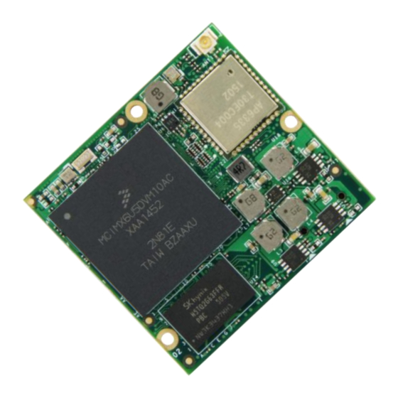
PICO-IMX6 REV. A1. HARDWARE MANUAL – VER 1.01 – JAN 28 2016 1.6. Component Location Figure 5 - PICO-IMX6 Top view Item Description Item Description NXP i.MX6 Processor Memory IC BCM4339 WiFi/Bluetooth IC Antenna connector Figure 6 - PICO-IMX6-SD Bottom view... -
Page 14: Figure 7 - Pico-Imx6-Emmc Bottom View
PICO-IMX6 REV. A1. HARDWARE MANUAL – VER 1.01 – JAN 28 2016 Figure 7 - PICO-IMX6-EMMC Bottom view Item Description Item Description Memory IC eMMC Storage IC Intel® Edison Compatible Connector Expansion Connector 1 Expansion Connector 2 Page 14 of 64... -
Page 15: Core Components
PICO-IMX6 REV. A1. HARDWARE MANUAL – VER 1.01 – JAN 28 2016 2. Core Components 2.1. NXP i.MX6 Cortex-A9 Multi-core Processor The NXP i.MX6 processor is an implementation of the Single/Dual/Quad ARM Cortex™-A9 core, which operates at frequencies up to 1.2 GHz. The i.MX6 provides a variety of interfaces and supports the following main features: ... -
Page 16: Figure 9 - Nxp I.mx6 Processor Scalability Overview (Solo/Duallite/Dual/Quad)
PICO-IMX6 REV. A1. HARDWARE MANUAL – VER 1.01 – JAN 28 2016 Figure 9 - NXP i.MX6 Processor Scalability Overview (Solo/Duallite/Dual/Quad) Page 16 of 64... -
Page 17: I.mx6 Memory Interfaces
PICO-IMX6 REV. A1. HARDWARE MANUAL – VER 1.01 – JAN 28 2016 2.1.1. i.MX6 Memory Interfaces The memory system consists of the following components: Level 1 Cache—32 KB Instruction, 32 KB Data cache per core Level 2 Cache—Unified instruction and data (1 MByte) ... -
Page 18: I.mx6 Video And Graphics Subsystems
PICO-IMX6 REV. A1. HARDWARE MANUAL – VER 1.01 – JAN 28 2016 2.1.3. i.MX6 Video and Graphics Subsystems The PICO-IMX6 video graphics subsystem consists of the following i.MX6 sub-blocks. VPU: A multi-standard high performance video codec engine supporting encode/decode operations of the following: Decoding: H.264 BP/CBP/MP/HP, VC-1 SP/MP/AP, MPEG-4 SP/ASP, H.263 P0/P3,... -
Page 19: Memory
PICO-IMX6 REV. A1. HARDWARE MANUAL – VER 1.01 – JAN 28 2016 2.2. Memory The PICO-IMX6 integrates Double Data Rate III (DDR3) Synchronous DRAM in a single (32 bit) channel configuration. The following memory chips have been validated and tested on the PICO-IMX6 Compute Module: 2.2.1 SKHynix... -
Page 20: Micron
PICO-IMX6 REV. A1. HARDWARE MANUAL – VER 1.01 – JAN 28 2016 2.2.2. Micron Micron 1.35V DDR3L SDRAM device is a low-voltage version of the 1.5V DDR3 SDRAM device. Unless stated otherwise, the DDR3L SDRAM device meets the functional and timing specifications listed in the equivalent density standard or automotive DDR3 SDRAM data sheet located on www.micron.com. -
Page 21: Emmc Storage (Pico-Imx6-Emmc Only)
PICO-IMX6 REV. A1. HARDWARE MANUAL – VER 1.01 – JAN 28 2016 2.3. eMMC Storage (PICO-IMX6-EMMC Only) The PICO-IMX6 can be ordered with onboard eMMC storage in different configurations and capacity. The onboard eMMC device is connected on the SD3 pins of the i.MX6 processor in an 8 bit width configuration. -
Page 22: Kingston Ke4Cn2H5A
PICO-IMX6 REV. A1. HARDWARE MANUAL – VER 1.01 – JAN 28 2016 2.3.2. Kingston KE4CN2H5A Kingston e•MMC™ products follow the JEDEC e•MMC™ 4.5 standard. It is an ideal universal storage solutions for many electronic devices, including smartphones, tablet PCs, PDAs, eBook readers, digital cameras, recorders, MP3, MP4 players, electronic learning products, digital TVs and set-top boxes. -
Page 23: Micro-Sd Cardslot (Pico-Imx6-Sd Only)
PICO-IMX6 REV. A1. HARDWARE MANUAL – VER 1.01 – JAN 28 2016 Table 2 - eMMC Signal Description CPU PAD NAME Signal Description BALL SD3_DAT0 eMMC_DATA0 MMC/SDIO Data bit 0 SD3_DAT1 eMMC_DATA1 MMC/SDIO Data bit 1 SD3_DAT2 eMMC_DATA2 MMC/SDIO Data bit 2... -
Page 24: Broadcom Bcm4339 Wifi/Bluetooth Sip Module
PICO-IMX6 REV. A1. HARDWARE MANUAL – VER 1.01 – JAN 28 2016 2.5. Broadcom BCM4339 WiFi/Bluetooth SiP Module The PICO-IMX6 can be ordered with an optional onboard WiFI/Bluetooth SIP module. The 802.11ac + BT SiP module is a small sized BGA mounted module that provides full function of 802.11ac and Bluetooth class 4.0 +HS... -
Page 25: Table 4 - Bcm4339 Wifi Signal Description
PICO-IMX6 REV. A1. HARDWARE MANUAL – VER 1.01 – JAN 28 2016 Table 4 - BCM4339 WiFi Signal Description i.MX6 PAD NAME Signal Description BALL SD2_DAT0 SDIO_D0 MMC/SDIO Data bit 0 SD2_DAT1 SDIO_D1 MMC/SDIO Data bit 1 SD2_DAT2 SDIO_D2 MMC/SDIO Data bit 2... -
Page 26: Table 5 - Bcm4339 Bluetooth Signal Description
PICO-IMX6 REV. A1. HARDWARE MANUAL – VER 1.01 – JAN 28 2016 Table 5 - BCM4339 Bluetooth Signal Description i.MX6 PAD NAME Signal Description BALL SD4_DAT7 BT_UART_RXD Bluetooth UART Serial Input. Serial data “UART2_TXD” input for the HCI UART Interface... -
Page 27: Pico Compute Module Connector Interfaces
3. PICO Compute Module Connector Interfaces 3.1 Ethernet The PICO-IMX6 implements a triple speed 10/100/1000 Mbit/s Ethernet MAC compliant with the IEEE802.3-2002 standard. The MAC layer provides compatibility with half- or full-duplex 10/100 Mbit/s Ethernet LANs and full-duplex gigabit Ethernet LANs. -
Page 28: Hdmi (High Definition Multi-Media Interface)
PICO-IMX6 REV. A1. HARDWARE MANUAL – VER 1.01 – JAN 28 2016 3.2. HDMI (High Definition Multi-Media Interface) The HDMI interface available with PICO-IMX6 is based on the “HDMI transmitter” & “HDMI 3D Tx PHY” integrated into the i.MX6 processor. The “HDMI transmitter” combines video/display data from the IPU, Audio data from i.MX6 memory &... -
Page 29: Lvds Interface
PICO-IMX6 REV. A1. HARDWARE MANUAL – VER 1.01 – JAN 28 2016 3.3. LVDS Interface The PICO-IMX6 is equipped with single LVDS Display interfaces. The LVDS Display Bridge (LDB) connects the IPU (Image Processing Unit) to an External LVDS Display Interface. The purpose of the LDB is to support flow of synchronous RGB data from the IPU to external display devices through LVDS interface. -
Page 30: Digital Display Sub-System (Dss) Or Ttl Interface
PICO-IMX6 REV. A1. HARDWARE MANUAL – VER 1.01 – JAN 28 2016 3.4. Digital Display Sub-System (DSS) or TTL Interface The Parallel Display interface of PICO-IMX6 is derived directly from the DI0 port of the IPU, effectively bypassing all the i.MX6 integrated display bridges. -
Page 31: Table 9 - Ttl Display Signal Description
PICO-IMX6 REV. A1. HARDWARE MANUAL – VER 1.01 – JAN 28 2016 Table 9 - TTL Display Signal Description CPU PAD NAME Signal Description BALL X1_8 DISP0_DAT23 DISP0_DAT23 LCD Pixel Data bit 23 X1_10 DISP0_DAT22 DISP0_DAT22 LCD Pixel Data bit 22... -
Page 32: Mipi Display
PICO-IMX6 REV. A1. HARDWARE MANUAL – VER 1.01 – JAN 28 2016 3.5. MIPI Display The PICO-IMX6 provides MIPI Serial Interface camera signals. The MIPI DSI Host Controller supports the following features: IPU SIDE (input): Compliant with MIPI Alliance Specification for Display Serial Interface (DSI), Version 1.01.00 - 21 February 2008 ... -
Page 33: Mipi Camera
PICO-IMX6 REV. A1. HARDWARE MANUAL – VER 1.01 – JAN 28 2016 3.6. MIPI Camera The PICO-IMX6 provides MIPI Serial Interface camera signals. The MIPI CSI-2 Host Controller supports the following features: Compliant with MIPI Alliance Standard for Camera Serial Interface 2 (CSI-2), Version 1.00 – 29 November 2005 ... -
Page 34: Audio Interface
PICO-IMX6 REV. A1. HARDWARE MANUAL – VER 1.01 – JAN 28 2016 3.7. Audio Interface The PICO-IMX6 incorporates one I S / AUDMUX instance and can as well provide surround audio over the HDMI data signals. The AUDMUX provides flexible, programmable routing of the serial interfaces (SSI1 or SSI2) to and from off-chip devices. -
Page 35: Pci Express
PICO-IMX6 REV. A1. HARDWARE MANUAL – VER 1.01 – JAN 28 2016 3.8. PCI Express The PICO-IMX6 is equipped with a single lane PCI Express interface, implemented in the i.MX6 processor. The PCI Express interface complies with PCIe specification Gen 2.0 and supports the PCI Express 1.1/2.0 standards. -
Page 36: Serial Ata Interface
3.9. Serial ATA Interface The PICO-IMX6 incorporates a single SATA-II port implemented with the NXP i.MX6 integrated SATA controller and PHY when the PICO-IMX6 is featured with a i.MX6 Dual or Quad Processor. (Availability restrictions apply) The interface supports the following main features: ... -
Page 37: Universal Serial Bus (Usb) Interface
PICO-IMX6 REV. A1. HARDWARE MANUAL – VER 1.01 – JAN 28 2016 3.10. Universal Serial Bus (USB) Interface The PICO-IMX6 incorporates a single USB Host controller and an additional USB Host/OTG controller. Each of the USB controllers provides the following main features: USB 2.0 Host/OTG Controller... -
Page 38: Sdio/Mmc Interface
PICO-IMX6 REV. A1. HARDWARE MANUAL – VER 1.01 – JAN 28 2016 3.11. SDIO/MMC Interface The PICO-IMX6 features a MMC / SD / SDIO host interfaces connected to the NXP i.MX6 integrated “Ultra Secured Digital Host Controller” (uSDHC). The following main features are supported by uSDHC: ... -
Page 39: Can Bus Interface Signals
PICO-IMX6 REV. A1. HARDWARE MANUAL – VER 1.01 – JAN 28 2016 3.12. CAN BUS Interface signals The PICO-IMX6 features two CAN bus interfaces. The CAN bus interfaces are implemented with the i.MX6 on chip “Flexible Controller Area Network” (FlexCAN) communication modules. -
Page 40: Universal Asynchronous Receiver/Transmitter (Uart) Interface
PICO-IMX6 REV. A1. HARDWARE MANUAL – VER 1.01 – JAN 28 2016 3.13. Universal Asynchronous Receiver/Transmitter (UART) Interface The PICO-IMX6 makes 2 UART ports available and utilizes an additional UART on the module to connect to the WiFi/Bluetooth module. The i.MX6 processor integrated UARTs support the following features: ... -
Page 41: Serial Peripheral Interface (Spi)
PICO-IMX6 REV. A1. HARDWARE MANUAL – VER 1.01 – JAN 28 2016 3.14. Serial Peripheral Interface (SPI) The PICO -IMX6 features two Enhanced Configurable SPI ports, which are derived from the i.MX6 processor, integrated ECSPI IPs. The following main features are supported: ... -
Page 42: I 2 C Bus
PICO-IMX6 REV. A1. HARDWARE MANUAL – VER 1.01 – JAN 28 2016 3.15. I C Bus The PICO-IMX6 I C interfaces are implemented with the i.MX6 integrated I C controller. There are two general purpose I C interfaces and one I C interface dedicated towards display and system management functions. -
Page 43: General Purpose Input/Output (Gpio)
3.16. General Purpose Input/Output (GPIO) The PICO-IMX6 has 10 dedicated GPIO pins at 1.8V and 3 dedicated GPIO pins at 3.3V. Many of the other pins used on the PICO Compute Module can be put in GPIO module however doing so might break scalability with other PICO Compute Modules. -
Page 44: Pulse Width Modulation (Pwm)
PICO-IMX6 REV. A1. HARDWARE MANUAL – VER 1.01 – JAN 28 2016 3.17. Pulse Width Modulation (PWM) The PICO-IMX6 has 4 dedicated PWM pins at 1.8V. The following features characterize the PWM: 16-bit up-counter with clock source selection ... -
Page 45: Manufacturing And Boot Control
PICO-IMX6 REV. A1. HARDWARE MANUAL – VER 1.01 – JAN 28 2016 3.18. Manufacturing and Boot Control The PICO-IMX6 has a number of pins to override the default boot media present on the PICO-IMX6 Compute Module (eMMC or SD Cardslot). -
Page 46: Input Power Requirements
±50 mV 3.19.1. Power Management Signals The PICO-IMX6 has the following set of signals to control the system power states such as the power-on and reset conditions. This enables the system designer to implement a fully ACPI compliant system supporting system states. -
Page 47: Power Sequence
PICO-IMX6 REV. A1. HARDWARE MANUAL – VER 1.01 – JAN 28 2016 3.19.2. Power Sequence PICO-IMX6 input power sequencing requirements are as follow: If a backup Real Time Clock (RTC) is required in the host system. We recommend to design an RTC circuit on the PICO carrier board. -
Page 48: Pico Compute Module Pin Assignment
PICO-IMX6 REV. A1. HARDWARE MANUAL – VER 1.01 – JAN 28 2016 4. PICO Compute Module Pin Assignment The PICO-IMX6 has three 70-pin Hirose board to board connectors. CPU PAD NAME Signal Description BALL E1_1 Ground System input power (4.0 to... - Page 49 PICO-IMX6 REV. A1. HARDWARE MANUAL – VER 1.01 – JAN 28 2016 CPU PAD NAME Signal Description BALL Universal Serial Bus E1_18 USB_OTG_DN USB_OTG_DN differential pair negative signal Over current detect input pin E1_19 EIM_D30 FAULT to monitor USB power over...
- Page 50 PICO-IMX6 REV. A1. HARDWARE MANUAL – VER 1.01 – JAN 28 2016 CPU PAD NAME Signal Description BALL Universal Asynchronous E1_46 EIM_D24 UART3_TXD Receive Transmit transmit data signal E1_47 EIM_D18 I2C3_SDA C bus data line General Purpose Input E1_48 CSI0_DAT15...
- Page 51 PICO-IMX6 REV. A1. HARDWARE MANUAL – VER 1.01 – JAN 28 2016 CPU PAD NAME Signal Description BALL X1_1 Ground X1_2 Ground LVDS differential pair 3 X1_3 LVDS0_TX3_N LVDS0_TX3_N negative signal X1_4 SD4_DAT0 LVDS0_BLT_EN LVDS panel backlight enable LVDS differential pair 3...
- Page 52 PICO-IMX6 REV. A1. HARDWARE MANUAL – VER 1.01 – JAN 28 2016 CPU PAD NAME Signal Description BALL X1_42 DISP0_DAT6 DISP0_DAT6 LCD Pixel Data bit 6 X1_43 RGMII_TX_CTL RGMII_TXEN RGMII transmit enable X1_44 DISP0_DAT5 DISP0_DAT5 LCD Pixel Data bit 5...
- Page 53 PICO-IMX6 REV. A1. HARDWARE MANUAL – VER 1.01 – JAN 28 2016 CPU PAD NAME Signal Description BALL X2_1 Ground X2_2 Ground X2_3 EIM_DA12 EIM_DA12 Boot Select pin Serial ATA Receive X2_4 SATA_RXP SATA1_RXP differential pair positive signal X2_5 EIM_DA14...
- Page 54 PICO-IMX6 REV. A1. HARDWARE MANUAL – VER 1.01 – JAN 28 2016 CPU PAD NAME Signal Description BALL MIPI Camera Serial Interface X2_33 CSI_CLK0P CSI_CLK0P clock pair positive signal HDMI differential pair clock X2_34 HDMI_CLKP HDMI1_CLKP positive signal MIPI Camera Serial Interface...
- Page 55 PICO-IMX6 REV. A1. HARDWARE MANUAL – VER 1.01 – JAN 28 2016 CPU PAD NAME Signal Description BALL X2_60 Ground MIPI Display Serial Interface X2_61 DSI_CLK0M DSI_CLK0M clock pair negative signal PCI Express Transmit output X2_62 PCIE_TXP PCIEA_TXP differential pair positive...
-
Page 56: Development Kits, Proto-Type Components And Accessories
PICO-IMX6 REV. A1. HARDWARE MANUAL – VER 1.01 – JAN 28 2016 5. Development Kits, Proto-type Components and Accessories To evaluate the PICO-IMX6 TechNexion has made available a large number of evaluation kits and accessories available. 5.1. PICO-IMX6 Evaluation Kits 5.1.1. -
Page 57: Pico Compatible Displays
PICO-IMX6 REV. A1. HARDWARE MANUAL – VER 1.01 – JAN 28 2016 5.2. PICO Compatible Displays 5.2.1. LVDSEXPANDER Translation Board to Connect to LVDS Panels Partnumber Description LVDSEXPANDER Expansion Translation Board to connect to LVDS Panels Page 57 of 64... -
Page 58: Tdhj070Na4Reskit Resistive Touch Display Kit Pack Content
Touch panel link cable NOTE: To connect to PICO-DWARF or PICO-HOBBIT you will also need to purchase LVDS-EXPANDER. NOTE: Many other display and touch solutions are available. Please connect with your TechNexion distributor or account manager for conditions and availability. -
Page 59: Tdhj070Napcapkit Pcap Touch Display Kit Pack Content
USB Touch panel link cable NOTE: To connect to PICO-DWARF or PICO-HOBBIT you will also need to purchase LVDS-EXPANDER. NOTE: Many other display and touch solutions are available. Please connect with your TechNexion distributor or account manager for conditions and availability. -
Page 60: Accessories
PICO-IMX6 REV. A1. HARDWARE MANUAL – VER 1.01 – JAN 28 2016 5.3. Accessories 5.3.1. EDMANTP150A138045D2450BK Pack Content. Partnumber Description EDMANTP150A138045D2450BK 4.5 dB, 2.4/5 GHz, black color antenna u.FL to SMA patch cable Page 60 of 64... -
Page 61: Pico Compute Module Product Ordering Part Numbers
PICO-IMX6 REV. A1. HARDWARE MANUAL – VER 1.01 – JAN 28 2016 5.4. PICO Compute Module Product Ordering Part Numbers The PICO-IMX6 is available in a number of standard configurations. Custom tailored versions with other memory configuration, de-population of interfaces or extended and industrial temperature options are available upon request. -
Page 62: Custom Part Number Creation Rules
PICO-IMX6 REV. A1. HARDWARE MANUAL – VER 1.01 – JAN 28 2016 5.4.2. Custom Part Number Creation Rules The PICO-IMX6 can be ordered in custom tailored to meet special application requirements and conditions according to the following custom part number creation rules. -
Page 63: Important Notice
Information published by TechNexion regarding third-party products or services does not constitute a license from TechNexion to use such products or services or a warranty or endorsement thereof. Use of such information may require a license from a third party under the patents or other intellectual property of the third party, or a license from TechNexion under the patents or other intellectual property of TechNexion. -
Page 64: Disclaimer
To the extent permitted by law no liability (including liability to any person by reason of negligence) will be accepted by TechNexion Ltd., its subsidiaries or employees for any direct or indirect loss or damage caused by omissions from or inaccuracies in this document.
Need help?
Do you have a question about the PICO-IMX6 and is the answer not in the manual?
Questions and answers