Sign In
Upload
Manuals
Brands
TechNexion Manuals
Control Unit
FLEX-IMX8M-Mini
User Manuals: TechNexion FLEX-IMX8M-Mini Module
Manuals and User Guides for TechNexion FLEX-IMX8M-Mini Module. We have
1
TechNexion FLEX-IMX8M-Mini Module manual available for free PDF download: Product Manual
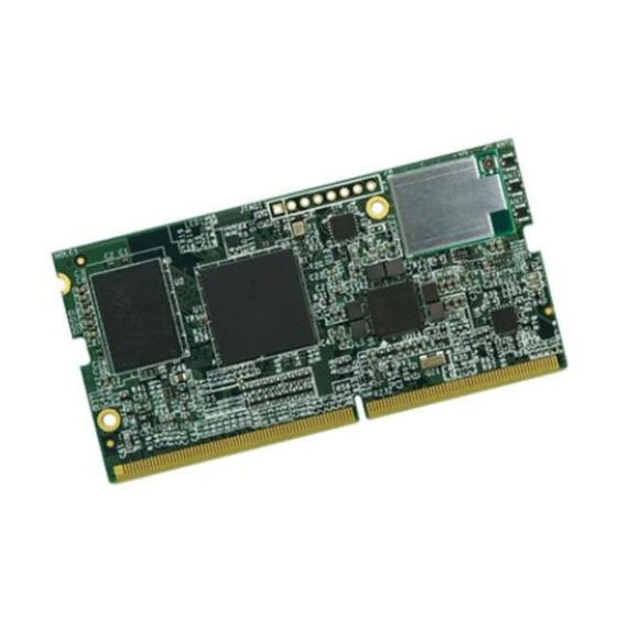
TechNexion FLEX-IMX8M-Mini Product Manual (48 pages)
SYSTEM ON MODULE WITH NXP i.MX8M Mini SoC
Brand:
TechNexion
| Category:
Control Unit
| Size: 1 MB
Table of Contents
Table of Contents
3
1 Introduction
5
General Introduction
5
2 FLEX-IMX8M-Mini Product Overview
5
FLEX-IMX8M-Mini System-On-Module Overview
5
Figure 1 - FLEX-IMX8M-Mini System-On-Module
5
Block Diagram
6
Dimensional Drawing
6
Figure 2 - FLEX-IMX8-Mini System-On-Module Block Diagram Overview
6
Figure 3 - FLEX-IMX8-Mini System-On-Module Dimensions
6
Component Location
7
Figure 4 - FLEX-IMX8M-Mini Top View
7
Figure 5 - FLEX-IMX8M-Mini Bottom View
7
3 Core Components
8
NXP I.mx8M Mini ARM Cortex-A53 + Cortex-M4 Processor
8
Figure 6 - NXP I.mx8M-Mini Processor Blocks
9
Power Management IC (ROHM BD71847)
10
ROHM BD71847 Reset Signal
10
Table 1 - PMIC Signal Description
10
Table 2 - PMIC Reset Signal Description
10
Table 3 - PMIC Hard Reset Signal Description
10
Memory
11
Emmc Storage
11
Table 4 - Emmc Signal Description
11
Wi-Fi/Bluetooth
12
Figure 7 - FLEX-IMX8M-Mini Wi-Fi Module and Antenna Connector Location
12
Table 5 - Wi-Fi Signal Description
13
Table 6 - Bluetooth Signal Description
14
Atheros AR8035 Gigabit LAN
15
Table 7 - Gigabit Ethernet Interconnect between I.mx8M Mini and AR8035
16
Jtag
17
Table 8 - JTAG Signal Description
17
Figure 8 - FLEX-IMX8M-Mini JTAG Connector
17
4 FLEX Compute Module Pin Assignment
18
Table 9 - FLEX Compute Module Pin Assignment
18
Figure 9 - FLEX-IMX8M-Mini Board-To-Board Connectors
18
5 FLEX-IMX8M-Mini External Interfaces
27
Ethernet
27
Table 10 - Ethernet Signal Description
27
MIPI Display
28
Table 11 - MIPI Display Signal Description
29
MIPI Camera
30
Table 12 - MIPI Camera Control Signals
31
Audio Interface
32
Table 13 - I2S-1 Audio Signal Description
33
Table 14 - I2S-2 Audio Signal Description
33
PCI Express
34
Table 15 - PCI Express Signal Description
34
Universal Serial Bus (USB) Interface
35
Table 16 - USB Host Signal Description
35
Table 17 - USB OTG Signal Description
36
SDIO/MMC Interface
37
Table 18 - SDIO Signal Description
37
Universal Asynchronous Receiver/Transmitter (UART) Interface
38
Table 19 - UART3 Signal Description
39
Table 20 - UART2 Signal Description
39
Serial Peripheral Interface (SPI)
40
Table 21 - SPI Signal Description
40
I 2 C Bus
41
I 2 C Bit Bang Interface
41
Table 22 - I C Bus Signal Description
41
General Purpose Input / Output (GPIO)
42
Table 23 - GPIO Signal Description
42
Pulse Width Modulation (PWM)
43
Table 24 - PWM Signal Description
43
Manufacturing and Boot Control
44
Emmc Boot Mode
44
Serial Downloader Boot Mode
44
SD Card Boot Mode
44
Table 25 - Boot Selection Pins
44
Table 26 - Serial Downloader Boot Mode Configuration
44
Table 27 - SD Card Boot Mode Configuration
44
Input Power Requirements
45
Reference and Output Power
45
Table 28 - Input Power Signals
45
Table 29 - Power Management Signals
45
6 Ordering Information
46
FLEX Compute Module Product Ordering Part Numbers
46
Custom Part Number Rule
46
7 Important Notice
47
8 Disclaimer
48
Advertisement
Advertisement
Related Products
TechNexion EDM1-IMX6
TechNexion EDM1-IMX6PLUS
TechNexion PICO-IMX6
TechNexion PICO-IMX6UL-EMMC
TechNexion PICO-IMX8M
TechNexion TAM-3517
TechNexion Categories
Motherboard
Control Unit
Desktop
Touch Panel
Single board computers
More TechNexion Manuals
Login
Sign In
OR
Sign in with Facebook
Sign in with Google
Upload manual
Upload from disk
Upload from URL