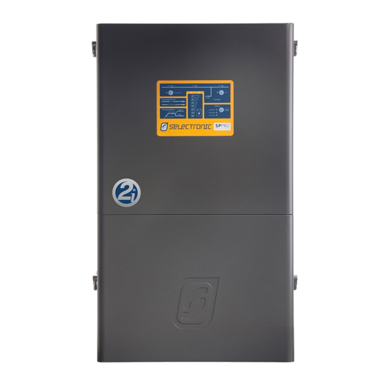
Selectronic SP PRO 2i Series Instruction Manual

Selectronic SP PRO 2i Series Instruction Manual

Interactive inverter charger
Hide thumbs Also See for SP PRO 2i Series:
Table of Contents

Advertisement

Quick Links

Instruction Manual for
SP PRO series 2i
Interactive Inverter Charger
Installation • Operation • Service

Advertisement

Table of Contents
loading
Need help?

Need help?

Do you have a question about the SP PRO 2i Series and is the answer not in the manual?

Questions and answers

Subscribe to Our Youtube Channel

Summary of Contents for Selectronic SP PRO 2i Series

  • Page 1 Instruction Manual for SP PRO series 2i Interactive Inverter Charger Installation • Operation • Service...
  • Page 2 Selectronic Australia Pty Ltd © 2020 Ph +61 3 9727 6600 Fax +61 3 9727 6601 www.selectronic.com.au...
  • Page 3 INTRODUCTION Thank you for purchasing a Selectronic SP PRO series 2i sine wave Interactive Inverter Charger optimised for either grid connected power systems (also called Solar Hybrid Power Systems) or Off Grid systems (no grid power available). Selectronic has an accredited Quality Assurance system covering both their manufacturing and design operations with over 25 years experience designing power conversion equipment for both domestic and industrial purposes.
  • Page 4: Table Of Contents

    Contents Contents INTRODUCTION Battery Temperature Sensor Battery Wiring (DC) Preparation Australian/New Zealand Warranty AC Wiring Using This Manual Earth Wiring Included in this package Residual Current Device (RCD) Type Glossary of Terms Recommendation Configuring the SP PRO using SP LINK AC Wiring Preparation Product Overview Backup Generator (Advanced Feature) Control...
  • Page 5 Contents SERVICE Installation-Commissioning Introduction Service and Maintenance Diagnostics during Commissioning Common System Checks Multiple Sources of Supply Powerchain Systems Cleaning the Fan and Fan Filter External AC Source Contactor Monitoring the operation of the SP PRO Continue Common System Checks System Shutdown and Startup Checking Managed AC Coupled Systems Installer Maintenance of SP PRO...
  • Page 6: Introduction

    INTRODUCTION | Warranty and manual use Australian/New Zealand Warranty The Selectronic SP PRO product is warranted by the manufacturer to the original purchaser only. The manufacturer will bear the cost of parts and labour to repair any faults found within the terms and period of this warranty.
  • Page 7: Included In This Package

    Tool kit - (Hex Drive bits - T10 Torx, T20 Torx, T25 Torx, 5 mm Hex, 6 mm Hex, long extension) • USB Cable - Type B SP LINK software: Download the latest version from the Selectronic web site www.selectronic.com.au Glossary of Terms...
  • Page 8: Product Overview

    Its advanced features include the precise control of either a Selectronic Certified (SCERT) grid tie inverter or the Selectronic SelectSun grid tie inverter, making it ideal for either an Off Grid charging system or maintain a Solar Hybrid export limit.
  • Page 9: Off Grid Stand Alone Power Systems (Sps)

    INTRODUCTION | Product Overview In Solar Hybrid, the renewable energy can be directed to power the AC load, recharge the battery bank and/ or export to the grid. The direction and priority of the energy flow can be varied depending on the time of day, battery SoC or load demands allowing the maximum use of the renewable energy (such as PV solar) and stored battery energy to supply loads to take advantage of variable electricity tariffs.
  • Page 10: Precautions And Safety

    Selectronic Australia shall have no obligation as to any equipment which has been improperly installed, stored, or handled, or which has not been operated or maintained according to this manual, nor for any operating mistakes and consequences arising from them.
  • Page 11: Preparation

    “Included in the Package” section of this manual. Please report any damage or missing parts to Selectronic or a Selectronic Authorised Distributor. Please retain the original packaging for the safest and most effective method of repackaging if required.
  • Page 12: Installation

    “Installation-Specific Applications” Section in this manual and the relevant installation guide supplied with any required installation options. All installation notes including this manual can be downloaded from the Selectronic web site at: www.selectronic.com.au...
  • Page 13: Environmental Considerations

    INSTALLATION | General Requirements Environmental Considerations ENVIRONMENTAL CATEGORY The SP PRO is design with an Environmental Category (as defined by IEC 62109.1) for “Indoor, unconditioned. The SP PRO must be protected by a building or enclosure from direct rain, sun, wind-blown dust, fungus and radiation to the night sky.
  • Page 14: Preparation

    INSTALLATION | General Requirements Preparation The selection of a suitable site and good preparation is essential in gaining optimum performance from the SP PRO. SP PRO Inverter performance is dependent upon the environmental operating conditions, in particular ambient temperature and ventilation. In addition safety aspects must be considered, such as: •...
  • Page 15: Installation Of Spmc Models

    INSTALLATION | Installation of SPMC models Installation of SPMC models - Unpack the SP PRO onto a flat surface. When removing the SP PRO from its packaging carefully inspect for any damage that may have occurred in transit. Damage must be reported to the supplier immediately. Doc #OI0003 Part #004122 Rev29 2020...
  • Page 16 INSTALLATION | Installation of SPMC models - Diagram previous page. Choose a suitable weight bearing and temperature resistant surface to mount the SP PRO. Mounting MUST be to solid timber studs, solid timber, brick, masonry or other load bearing wall. DO NOT mount directly to plaster.
  • Page 17 INSTALLATION | Installation of SPMC models 8- Wiring must only be carried out by When all the AC wiring is complete reinstall the suitably qualified installers and must terminal cover and expansion card. adhere to all relevant standards. Important points •...
  • Page 18: Installation Of Splc Models

    INSTALLATION | Installation of SPLC models Installation of SPLC models - Undo ten bolts ( “) to remove lid on packing crate. Cardboard tray contains mounting plate, rear air outlet mesh cover and all documentation. Inspect for damage in transit and report any to the supplier immediately.
  • Page 19 INSTALLATION | Installation of SPLC models - Cable entry is either from below or wall entry. Gland plates are inter changeable . Gland plates secure to the underside of unit base or to the inside of the mounting plate using four T25 Torx screws. NOTE: Any wiring via the rear gland plate (attached to mounting bracket) can be ruffed in before mounting the SP PRO.
  • Page 20 INSTALLATION | Installation of SPLC models 7- Undo five T20 Torx screws to remove terminal - Wiring can only be carried out by plate. Expansion card remains secured to suitably qualified installers and must SP PRO. adhere to all relevant standards. Note: Expansion card not shown for clarity.
  • Page 21: Battery Cabling Requirements

    INSTALLATION | Cabling and fusing Battery Cabling Requirements The follow tables specify the minimum Recommended Copper Battery Cable Sizes for SP PRO inverter. NOTE: Please ensure the battery cabling and the fusing complies with relevant safety standards. Total distance per Minimum Size Copper Battery Cables per inverter.
  • Page 22: Dc Wiring Spmc Models

    INSTALLATION | Cabling and fusing DC Wiring SPMC Models WARNING: Copper wiring must be used throughout. Observe polarity of ALL battery wiring. Reverse battery polarity will cause irreversible damage. All SPMC models do NOT contain an internal fuse or DC breaker. The DC wiring must be fitted with appropriate fusing or circuit breakers.
  • Page 23: Expansion Card Warning - 120Vdc Model

    In “Dual” mode, the sense leads must be connected correctly – expansion card shunt terminal 1A or 2A to the solar and load side, 1B or 2B to the battery negative side. For More information please see “TN0045_xx SP PRO Shunt Installation” document available on the support page of the Selectronic web site: www.selectronic.com.au Battery Temperature Sensor...
  • Page 24: Battery Wiring (Dc) Preparation

    INSTALLATION | Cabling and fusing Battery Wiring (DC) Preparation The below schematic diagram shows the main battery isolator, battery sense / pre-charge isolator and included temperature sensor. For 48V and 120V battery banks it is a requirement that the Battery Sense / Precharge connections are used and wired directly back to the battery bank terminals.
  • Page 25: Ac Wiring

    INSTALLATION | Cabling and fusing AC Wiring The SP PRO is overvoltage category III meaning that it must be a fixed installation connected either downstream of (customer’s side) or directly to the main switchboard. WARNING: Copper wiring must be used throughout. The SP PRO does not contain internal circuit breakers of fuses.
  • Page 26: Residual Current Device (Rcd) Type Recommendation

    INSTALLATION | Cabling and fusing Residual Current Device (RCD) Type Recommendation The SP PRO produces a low distortion sine wave output via 50/60 Hz isolation transformer. This topology ensures that the output is sinusoidal and that there is no DC component associated with the SP PRO AC supply, whether that be feeding a domestic load or exporting solar to the grid.
  • Page 27: Backup Generator (Advanced Feature) Control Wiring

    INSTALLATION | Cabling and fusing Backup Generator (Advanced Feature) Control Wiring When a backup generator is installed, control wiring should be fed up through the appropriate gland and terminated to the SP PRO Expansion card. The minimum required is one pair of wires for a generator run signal which must be wired to one of the four relay outputs.
  • Page 28: Installation-System Configuration

    Everything required to configure the SP PRO in a Powerchain system comes standard with every SP PRO series 2i inverter. For more information on installing a Powerchain system see: “IN0057_xx Installation of an SP PRO Powerchain system” on the support page of the Selectronic website at: www.selectronic.com.au. Managed Battery Preparation...
  • Page 29: Managed Ac Coupled Preparation

    The SP PRO Managed AC Coupling provides a method of linking any of the Selectronic Certified grid tie inverters to the SP PRO via the AC Load supply so that regardless of whether the grid or a generator is connected, the SP PRO can manage and control the Selectronic Certified grid tie inverters.
  • Page 30 INSTALLATION | System Configuration Line diagram for single phase managed AC coupling The below diagrams detail the AC wiring requirements for Managed AC coupled systems. Please note that when a Solar Hybrid, Managed AC coupled system is installed with an existing grid connected PV system that has another brand of grid inverter (generic grid inverter) then the generic inverter is connected on the grid side of the system (See diagram below).
  • Page 31: Generic Ac Coupled Preparation

    Generic AC Coupled Preparation For full installation details see document “IN0034_xx SP PRO Generic AC Coupling installation notes” and SP LINK “Site Configuration Wizard”. available from the Selectronic Web site: www.selectronic.com.au To successfully install a SP PRO generic system, there are particular system requirements that need to be met.
  • Page 32: Powerchain - Three Phase Preparation

    A three phase system may be configured using up to twelve SP PRO inverters. For detailed information on preparing for a Three phase installation, please refer to the document “IN0057_xx Installation of a Powerchain system” on the support page of the Selectronic website at: www.selectronic.com.au.
  • Page 33: Dc Coupled Charge Controller Preparation

    State of Charge control or tracking. For more detail on installing and integrating a DC charge controller refer to the relevant document in the table below The latest versions of all documents can be found on the support page of the Selectronic website at www.selectronic.com.au...
  • Page 34: Installation-Ancillary Components

    INSTALLATION | Ancillary Components Installation-Ancillary Components Chapter Five Inputs and Output All SP PRO models come standard with four digital inputs, three digital outputs and four relay outputs. Additionally the 24V and 48 V models include two analogue inputs. Each input and output is fully programmable and can be used to provide advanced functionality. The ratings of the digital inputs and outputs are tabulated below Digital Inputs (x4) Maximum input voltage 60 V DC...
  • Page 35 INSTALLATION | Ancillary Components Setting name Function Low Batt Shutdown Forces the inverter to run after a low voltage shutdown. Used in an emergency Override Input to keep power running. Normal/Alternate AC Selects a second AC Source with a different capacity to the primary AC Source. Input Power Selector Inhibit Export Input Prevents the SP PRO from exporting power to the AC source.
  • Page 36 INSTALLATION | Ancillary Components Digital and Relay Outputs Each relay output has a normally open and normally closed set of dry contacts. These can be used directly to control devices requiring on/off type control. Each relay output is isolated from the next. If a 12V control signal is required then the relay output can be used to switch the internal 12V 0.8A supply on the communications card.
  • Page 37: External Ac Source Contactor

    The 12V supply on the SP PRO Comms card may be used to as the relay supply when using a relay with a 12V coil. For more detailed information please see “TN0057_xx SP PRO External AC Source Contactor Option” available from the selectronic web site: www.selectronic.com.au. Single phase external contactor Three phase external contactor Diagrams given as a reference only.
  • Page 38: Adding A Backup Generator (Solar Hybrid Only)

    For more detailed information please see “IN0020_xx 004799 SP Grid - Gen Backup Installation Notes” supplied with the Grid Fail / Generator Backup kit, or from the selectronic web site: www.selectronic.com.au. NOTE: A Grid Fail / Generator backup kit is not required when adding a generator to an Off Grid system.
  • Page 39: Adding A Generator (Off Grid Only)

    2 wire or 3 wire configuration. For more information on the control wiring please see document “TN0025_xx SP PRO Generator Controller Wiring Guide” Found on the Selectronic Web site. Line diagram for auto start generator - Off Grid System Diagram given as a reference only.
  • Page 40: Installation-Communications

    INSTALLATION | Communications Installation-Communications Chapter Six Communications Overview All SP PRO series 2i inverters come standard with a number of communications interfaces for connection to external system components. To further enhance the communication capability of the SP PRO a number of optional communication devices are available.
  • Page 41: Communications Port Functions

    SYNC 1 and SYNC 2 ports are used for inter inverter communications in a (RJ45) Powerchain configuration. RS485 Port 2 Used to communicate with up to five Selectronic Certified grid inverters in a managed (RJ45) AC coupled system. For more information see “Managed AC Coupled Preparation” on page 29...
  • Page 42: Select.live Remote Monitoring

    Select.live (Stock code 005283) is an optional communications interface that connects the SP PRO inverter to the Selectronic portal via WiFi or wired Ethernet. Once installed, the SP PRO based system may be monitored remotely from any web enabled device. Only one Select.live, connected to the System Manager, is required to monitor an entire Powerchain installation.
  • Page 43: Sp Pro Ethernet Adaptor

    Domain Names Servers (DNS). For more detailed information please see “TN0028_xx SP PRO Communications - Internet Connectivity”, available from the selectronic web site: www.selectronic.com.au Select.live is a more convenient and prefered method of remotely accessing the SP PRO via SP LINK.
  • Page 44: Installation-Configure With Sp Link

    More complex functionally may be added as required using Advanced Configuration . The latest version of SP LINK software is available from the Selectronic website at: www.selectronic.com.au. We strongly suggest that SP LINK is installed on your PC before going to the installation site.
  • Page 45: Configuring The Sp Pro For All System Configurations

    INSTALLATION | Using SP LINK Configuring The SP PRO For All System Configurations By installing and running the latest version of SP LINK, all standard Systems Configurations can be quickly and easily created and configured into the SP PRO. Simply run the Site Configuration Wizard, enter in the system details and SP LINK will validate the combination of system components and create a site file with a configuration for the SP PRO.
  • Page 46: Installation-Commissioning

    To ensure that you receive the highest level of support please ensure that the following commissioning documents are completed and available before contacting Selectronic Support. Please check off or record the value of all items in the following checklist. For Single phase systems just record the value for L1 (ignore L2 and L3).
  • Page 47: Common System Checks

    •The AC source terminals are wired to the grid or generator supply. •The AC load terminals are wired to the customer ’s loads •The AC outputs of the connected Selectronic Certified grid inverters are connected to the AC load terminals on the SP PRO(s).
  • Page 48: Powerchain Systems

    INSTALLATION | Commissioning Powerchain Systems For systems with more than one SP PRO in a Three Phase, Split Phase or multi-inverter single phase the following items should be verified. Please complete “Common System Checks” on page 47 first. For Systems with only one SP PRO and External Contactor, go to next page. For Systems with only one SP PRO and no External Contactor go to Continue Common System Checks.
  • Page 49: External Ac Source Contactor

    INSTALLATION | Commissioning External AC Source Contactor For single phase and multi-phase systems incorporating an external AC source Contactor, the following should be verified. Please note that these items are in addition any other items that are relevant to the system configuration.
  • Page 50: Continue Common System Checks

    INSTALLATION | Commissioning Continue Common System Checks Item to check Result Turn on the AC Source input to the SP PRO(s). DO NOT turn on the DC battery supply or the precharge/battery sense supply. Three blue LEDs will light up on each Phase manager. AC SOURCE, TRANSFER and AC LOAD.
  • Page 51: Checking Managed Ac Coupled Systems

    47 and other relevent sections should be completed first. Refer to relevant installation document for the particular brand of Selectronic Certified grid inverter (SCERT) and ensure the system has been installed and commissioned according to that document before completing the following checklist.
  • Page 52: Checking Generic Ac Coupled

    INSTALLATION | Commissioning Checking Generic AC Coupled For systems incorporating Generic AC Coupling the following items should be verified. Please note that “Common System Checks” on page 47 should be completed first. Refer to document “IN0034_xx SP PRO Generic AC Coupling installation notes” and ensure the system has been installed and commissioned according to this document before completing the following checklist.
  • Page 53: External Generator

    INSTALLATION | Commissioning External Generator For single phase and multi-phase systems incorporating a generator, the following should be verified. Please note that these items are in addition to any other items that are relevant to the system configuration. Please ensure the generator has been installed according to “Adding a Generator (Off Grid)” on page 39 and the document “TN0025_xx SP PRO Generator Controller Wiring Guide”, before completing the following checklist.
  • Page 54: Operation

    OPERATION | Controls and Indicators OPERATION Controls and Indicators Chapter Nine User Interface This section lists the controls and indicators found on the front panel of the SP PRO. The indicator brightness is adjusted according to the ambient light conditions (Blue LEDs exempted). AC SOURCE * When illuminated,this shows the presence of AC supply voltage from either the mains grid or backup generator (when installed), whichever is applicable.
  • Page 55 OPERATION | Controls and Indicators OUTPUT MODE STATUS SP PRO Battery supply disconnected. AC bypass only. Slow flashing Yellow SP PRO is Idle (off) - Monitoring and logging but no inverter AC output. Steady Green The SP PRO is On. Slow Flashing Green SP PRO Econo mode is active and is sensing load conditions.
  • Page 56: Sp Pro Operation

    OPERATION | SP PRO Operation SP PRO Operation Chapter Ten The following section describes in detail the operation of the SP PRO. A good understanding of the operation of the SP PRO and its parameters will enable configuration of the SP PRO to meet the system design requirements.
  • Page 57: Battery Management

    OPERATION | SP PRO Operation Battery Management Please refer to the battery manufacturer’s documentation for recommendations regarding settings for the particular battery. Inappropriate settings may have a detrimental affect on the battery life and performance. The SP PRO provides comprehensive battery management settings and controls to allow a charge regime to achieve optimal battery life.
  • Page 58: Battery Charging Operation

    OPERATION | SP PRO Operation Battery Charging Operation The SP PRO charging system manages all charging sources in the power system giving priority as appropriate to the renewable energy sources. This ensures that the renewable sources are used in the most cost effective manner.
  • Page 59: Battery Charging Cycle

    OPERATION | SP PRO Operation Doc #OI0003 Part #004122 Rev29 2020...
  • Page 60: Battery Temperature Compensation

    OPERATION | SP PRO Operation Battery Temperature Compensation The SP PRO monitors the temperature of unmanaged batteries via the sensor provided. The supplied battery temperature sensor must be mounted in thermal contact with the centre of the side of the battery. If the sensor is not in thermal contact with the battery bank, the batteries will not be correctly charged.
  • Page 61: Generator Controls For Off Grid

    • Avoid noise by only starting the generator late at night for heavy loads or a deeply discharged battery. For full details on backup generator controls please see “TN0025_xx SP PRO Generator Controller Wiring Guide” available on support page at the Selectronic web site. Backup Generator Controls (with option) The SP PRO may be configured to automatically control a backup generator in a Solar Hybrid power system using the optional “Grid fail - Gen backup”...
  • Page 62: Service

    SERVICE | Service and Maintenance SERVICE Service and Maintenance Chapter Eleven Multiple Sources of Supply Hazardous voltages and energy is generated by and are fed into the SP PRO by external wiring from multiple sources and may be stored in capacitors after switched off. Ensure the isolation of all energy sources.
  • Page 63: System Shutdown And Startup

    SERVICE | Service and Maintenance System Shutdown and Startup The Installer / integrator will provide detailed Shutdown and Restart instructions specific to the installation. Installer Maintenance of SP PRO Other than ensuring all AC and DC connections are always tight, there are only three areas that may require maintenance.
  • Page 64: Troubleshooting

    SERVICE | Troubleshooting Troubleshooting Chapter Twelve The SP PRO provides advanced monitoring of the power system and will advise the user when a problem develops with the power system. In most cases the problem and its cause can be determined by using the indicators provided with the SP PRO and information available via SP LINK.
  • Page 65 SERVICE | Troubleshooting 1. Alarm Silence button - Press this button to silence the SP PRO internal alarm after an alert. Pressing this button will silence the alarm for this instance only. The alarm will sound again with a new alert condition. 2.
  • Page 66: Troubleshooting With Sp Link

    “Using SP LINK and Performance Monitoring” section within the SP LINK manual for further information. Using the Performance Data Viewer within SP LINK, every aspect of the system and SP PRO can be analysed. If required, Selectronic can provide a second opinion (charges may apply) of the Performance Data.
  • Page 67: Ac Power Problems

    SERVICE | Troubleshooting AC Power Problems If the power fluctuates, lights go bright or dim but don’t go out. • Check the SP PRO front panel indicators and Performance data for information on the cause. • The SP PRO output may be varying due to starting very heavy loads. Check the output voltage reading (AC Load Voltage) via SP LINK.
  • Page 68: Off Grid Generator Start/Stop Problems

    SERVICE | Troubleshooting Off Grid Generator Start/Stop Problems Daily patterns of generator operation will change as the load supplied each day changes and as any renewable input such as solar increases or decreases from day to day or season to season. Using SP LINK check the “Generator Running Reason”...
  • Page 69: Inverter Startup Problems

    SERVICE | Troubleshooting Inverter Startup Problems SP PRO WILL NOT START If the indicators remain dark (not including the 3 blue LEDs along the top) when the SP PRO is switched on, then it is likely that DC battery power is not present. Check all the main battery wiring and terminals. Also check that the main battery fuse or circuit breaker is closed.
  • Page 70: Appendix A - Specifications

    C-tick Australia Product Specifications Note: Selectronic reserve the right to change specifications without notice. All ratings are at 25°C and nominal battery voltage unless otherwise stated. The product is specified to a maximum altitude of 2000 metres. Doc #OI0003 Part #004122 Rev29 2020...
  • Page 71 SERVICE | Appendix A - Specifications SP PRO SERIES SPECIFICATIONS SPMC240 SPMC241 SPMC480 SPMC481 SPMC482 SPMC1201 SPLC1200 SPLC1202 Nominal battery voltage 24 V 24 V 48 V 48 V 48 V 120 V 120 V 120 V Continuous, output power 3,000 W 4,500 W 3,500 W...
  • Page 72 Compatible with a number of Lithium battery brands with communications between the SP PRO and the battery BMS. between SP PRO and BMS . Please see the Selectronic web site for the list of approved batteries.. Aquious battery - Nominal voltage per stack...
  • Page 73 SERVICE | Appendix A - Specifications The RS232 ports are wired as DTE with their pinouts listed in the table below. Signal RS232 Port 1 RJ45 Signal RS232 Port 1 DB9 Signal RS232 Port 2 RJ45 +12V 0.8A supply +12V 0.8A supply Receive (Input) Data Data Terminal Ready Transmit (Output) Data...
  • Page 76 Selectronic Australia Pty Ltd © 2020 Ph +61 3 9727 6600 Fax +61 3 9727 6601 www.selectronic.com.au Doc #OI0003 Part #004122 Rev29 2020...

Table of Contents