Table of Contents
Advertisement
Quick Links
Description
Demonstration circuit 1788B features the
generation powered device (PD) controller for Power over
Ethernet (PoE) applications.
The DC1788B is available in DC1788B-A, DC1788B-B, and
DC1788B-C versions to meet the power level required by
the PD application. The DC1788B-A features the LT4275A
PD controller. This controller supports the IEEE 802.3at
(Type 2, PoE + ), IEEE 802.3af (Type 1, PoE) and LTPoE ++™
specification. LTPoE ++ adds four power levels to the ex-
isting IEEE standard with 38.7W, 52.7W, 70W, and 90W
of delivered PD power at the RJ45 jack. The DC1788B-B
features the LT4275B PD controller and is compliant with
the IEEE 802.3at and IEEE 802.3af specifications. The
DC1788B-C features the LT4275C PD controller and is
compliant with the IEEE 802.3af specification.
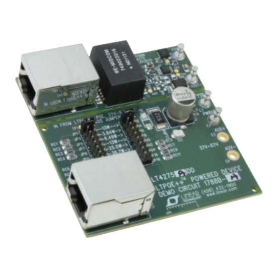
The DC1788B includes an RJ45 Ethernet port, a high
power Ethernet magnetic, a discrete active bridge recti-
fier, a surge protector, an external N-channel FET, and the
LT4275. The discrete active bridge rectifier is used to
achieve higher efficiency than a conventional diode bridge
rectifier. Many of the main features from the previous gen-
eration PD controller are included in this generation PD
Table 1. Summary of Features Supported by the DC1788B Assemblies
ASSEMBLY
PoE STANDARD
LTPoE ++
DC1788B-A
PoE +
PoE
PoE +
DC1788B-B
PoE
DC1788B-C
PoE
LT
4275, a fourth
controller. These include a power good indicator, a power
®
sourcing equipment (PSE) type indicator, and support
for an auxiliary power input. The major difference from
the previous generation PD controller is that the LT4275
drives an external N-channel Hot Swap™ FET at the PoE
high side voltage rail. This allows the user to choose a low
R
reduce heat dissipation, and ease thermal design. An LED
status indicator is included to indicate the Hot Swap FET
is fully turned on and the PSE is powering the PD. A suf-
ficient load to sink more than 10mA is also included to
assure the PSE maintains power to the PD and to meet
the DC maintain power signature current required by the
IEEE 802.3at/IEEE 802.3af specification.
Simply connect the output of the DC1788B to the DC/DC
converter that is right for the application. Linear Technology
offers a variety of DC/DC converter solutions that can be
used with the DC1788B (eg DC894, DC1317, etc).
Design files for this circuit board are available at
http://www.linear.com/demo
L, LT, LTC, LTM, Linear Technology and the Linear logo are registered trademarks and
LTPoE ++ and Hot Swap are trademarks of Linear Technology Corporation. All other trademarks
are the property of their respective owners.
MAXIMUM POWER
POWER GOOD
LEVEL
INDICATOR (PWRGD)
90W
25.5W
13W
DEMO MANUAL DC1788B
LTPoE ++ , IEEE 802.3at/
IEEE 802.3af Compliant
N-channel MOSFET to maximize power efficiency,
DS(ON)
PSE TYPE INDICATOR
(T2P)
Yes
Yes
Yes
Yes
Yes
No
LT4275
PD Controller
AUXILIARY SUPPLY
SUPPORT
No
Yes
Yes
dc1788bfa
1
Advertisement
Table of Contents

Related Manuals for Linear Technology DC1788B


Summary of Contents for Linear Technology DC1788B
- Page 1 Many of the main features from the previous gen- L, LT, LTC, LTM, Linear Technology and the Linear logo are registered trademarks and LTPoE ++ and Hot Swap are trademarks of Linear Technology Corporation. All other trademarks eration PD controller are included in this generation PD are the property of their respective owners.
-
Page 2: Performance Summary
IEEE 802.3at, and LTPoE ++ power levels from 3.84W to When an LTPoE ++ PSE is connected to the DC1788B demo 90W. Refer to Table 3 for the power levels. If an LTPoE ++ board RJ45 connector, J1, via a CAT5e or CAT6 Ethernet power level is selected, an IEEE 802.3af or IEEE 802.3at... - Page 3 Linear Technology offers a variety of PSE solutions to PSE Type Indicator evaluate with DC1788B. Refer to Table 5 to select a PSE demo board based on the DC1788B assembly and the Refer to Table 4 for the summary of T2P indicator signals application power requirement.
- Page 4 PD. Choose a power level from Table 3 detected and powered the PD and select the corresponding shunt positions. Figure 1. Setup Diagram for the DC1788B-A with a DC/DC Converter, a Microprocessor, and an LTPoE ++ PSE dc1788bfa...
- Page 5 (J1) on the DC1788B-B board with a CAT5e or CAT6 3. Turn on the auxiliary power supply and verify that the Ethernet cable. LED (D3) is lit. Figure 2. Setup Diagram for the DC1788B-B with a DC/DC Converter, a Microprocessor, and a Type 2 PSE dc1788bfa...
- Page 6 DEMO MANUAL DC1788B Dc1788B-B quick start proceDure Figure 3. Setup Diagram for the DC1788B-B with a DC/DC Converter, a Microprocessor, and an Auxiliary DC Power Supply dc1788bfa...
- Page 7 (J1) on the DC1788B-C board with a CAT5e or CAT6 3. Turn on the auxiliary power supply and verify that the Ethernet cable. LED (D3) is lit. Figure 4. Setup Diagram for the DC1788B-C with a DC/DC Converter and a Type 1 PSE dc1788bfa...
- Page 8 DEMO MANUAL DC1788B Dc1788B-c quick start proceDure Figure 5. Setup Diagram for the DC1788B-C with a DC/DC Converter and an Auxiliary DC Power Supply dc1788bfa...
-
Page 9: Quick Start Procedure
DEMO MANUAL DC1788B quick start proceDure Figure 6. DC1788B-A Efficiency at Various PoE Load Currents (without LED D3) Figure 7. Thermal Image. DC1788B-A with 90W Load. Top View dc1788bfa... - Page 10 DEMO MANUAL DC1788B quick start proceDure Figure 8. Thermal Image. DC1788B-A with 90W Load. Bottom View dc1788bfa...
-
Page 11: Parts List
DEMO MANUAL DC1788B parts list ITEM REFERENCE PART DESCRIPTION MANUFACTURER/PART NUMBER Required Circuit Components DC1788B General BOM Cap., X7R, 0.1µF , 100V, 10%, 0805 TDK, C2012X7R2A104K Cap., X7R, 47nF , 100V, 10%, 0805 AVX, 08051C473KAT2A Cap., X7R, 1nF , 2KV, 10%, 1808... - Page 12 DEMO MANUAL DC1788B parts list ITEM REFERENCE PART DESCRIPTION MANUFACTURER/PART NUMBER Hardware for Demo Board Only Cap., 22µF , 100V, OS-CON SUN ELECT., 100CE22BS Cap., X7R, 1nF , 2kV, 10%, 1808 TDK, C4520X7R3D102K LED, LN1351C-(TR), J-Type-LN1351CTR PANASONIC, LN1351C-(TR) E1, E2, E4 TP , Turret, 0.094"...
- Page 13 DEMO MANUAL DC1788B parts list ITEM REFERENCE PART DESCRIPTION MANUFACTURER/PART NUMBER Res., Chip, 0Ω, 5%, 0603 VISHAY, CRCW06030000Z0EA RMPS1 Res., Chip, 5.1k, 5%, 2512 VISHAY, CRCW25125K10JNEA RT5-RT8 Res., Chip, 75Ω, 5%, 0603 VISHAY, CRCW060375R0JNEA Fab, Printed Circuit Board DEMO CIRCUIT 1788B DC1788B-C BOM Cap., X5R, 0.1µF , 25V, 10%, 0603...
-
Page 14: Schematic Diagram
DEMO MANUAL DC1788B schematic Diagram RCLASS++ VPORTN RCLASS dc1788bfa... - Page 15 Information furnished by Linear Technology Corporation is believed to be accurate and reliable. However, no responsibility is assumed for its use. Linear Technology Corporation makes no representa- tion that the interconnection of its circuits as described herein will not infringe on existing patent rights.
- Page 16 Linear Technology Corporation (LTC) provides the enclosed product(s) under the following AS IS conditions: This demonstration board (DEMO BOARD) kit being sold or provided by Linear Technology is intended for use for ENGINEERING DEVELOPMENT OR EVALUATION PURPOSES ONLY and is not provided by LTC for commercial use. As such, the DEMO BOARD herein may not be complete in terms of required design-, marketing-, and/or manufacturing-related protective considerations, including but not limited to product safety measures typically found in finished commercial goods.
Need help?
Do you have a question about the DC1788B and is the answer not in the manual?
Questions and answers