Advertisement
Quick Links
DESCRIPTION
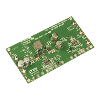
Demonstration circuit 1721B is a 14.6V, 5A battery charger
and PowerPath™ manager with 6V
converter featuring the LTC4000/LTC3789, targeted at
4-cell LiFePO
applications. The output of this demo board
4
was specifically tailored for a Tenergy 10A-hour battery,
P/N 30207. Other voltages can be set by changing ROFB2
and RBFB2. The desired nominal voltage can be accurately
trimmed by using trim resistors R42 and R43. For example,
for 14.4V battery float voltage, change ROFB2 and RBFB2
to 86.6k, and add 7.5M at R42 and R43 for greater set
point accuracy.
This circuit was designed to demonstrate the high levels of
performance, efficiency, and small solution size attainable
using these ICs in a buck-boost converter battery charger,
intelligent PowerPath manager, and power supply. It oper-
ates at 400kHz and produces a regulated 5A/14.6V battery
charger output as well as a system output of up to 6.25A
from an input voltage range of 6V to 36V: suitable for a
PERFORMANCE SUMMARY
SYMBOL
PARAMETER
V
Input Supply Range
IN
1
V
Input Regulation Voltage
IN-MP
2
I
Input Current Limit
IN
V
Battery Float Voltage
FLOAT
Output Regulation
I
Battery Charge Current
BAT
V
System Output Voltage
OUT-SYS
I
System Output Current Range
OUT-SYS
F
Switching (Clock) Frequency
SW
V
System Output Ripple
OUT-SYS P-P
P
/P
System Output Efficiency (See Figure 3) V
OUT
IN
Approximate Size
1
DC1721B-B (LTC4000-1) Only,
2
DC1721B-A (LTC4000) Only
Arrow.com.
Downloaded from
LTC4000EGN(-1)/LTC3789EGN
14.6V, 5A Battery Charger with
6V
to 36V
IN
to 36V
buck-boost
IN
IN
Specifications are at T
CONDITIONS
This Is the Input Voltage Lower Limit Set by the LTC4000-1
Line and Load (6V to 36V, 0A to 5A)
V
= 24V, I
= 5A (20MHz BW)
IN
OUT-SYS
= 24V, I
= 5A
IN
OUT-SYS
Component Area × Top Component Height
DEMO MANUAL
DC1721B-A/DC1721B-B
Buck-Boost Converter
IN
wide variety of portable applications including instruments,
industrial equipment, power tools, and computers. It has
a total footprint area of 12.4cm
circuit only). Synchronous rectification helps to attain
efficiency exceeding 96% at full load and nominal input.
DC1721B-A: The LTC4000 has an input current limit/
regulation loop that prevents overloading sources with
limited output capability.
DC1721B-B: The LTC4000-1 instead has an input voltage
regulation loop for Maximum Power Point (MPP) control.
MPP control extracts near maximum power from high
impedance sources such as solar panels, wind turbines,
or fuel cells.
Design files for this circuit board are available at
http://www.linear.com/demo
L, LT, LTC, LTM, Linear Technology and the Linear logo are registered trademarks and
PowerPath is a trademark of Linear Technology Corporation. All other trademarks are the
property of their respective owners.
= 25°C
A
2
2
(3.6cm
for the LTC4000
MIN
TYP
MAX
UNITS
6
36
V
11.85
V
11
A
14.4
14.6
14.8
V
±0.05
%
5.0
A
12.3
14.6
15.5
V
0
6.25
A
400
kHz
50
mV
P-P
96.5
%
× 0.40cm
2
12.4cm
dc1721bf
1
Advertisement

Related Manuals for Linear Technology DC1721B-B


Summary of Contents for Linear Technology DC1721B-B
- Page 1 400kHz and produces a regulated 5A/14.6V battery charger output as well as a system output of up to 6.25A L, LT, LTC, LTM, Linear Technology and the Linear logo are registered trademarks and PowerPath is a trademark of Linear Technology Corporation. All other trademarks are the from an input voltage range of 6V to 36V: suitable for a property of their respective owners.
-
Page 2: Quick Start Procedure
VIN and GND. observe charge current and trickle charge current. NOTE. 15. (DC1721B-B 0NLY) In order to observe MPP operation, add a 0.25Ω to 0.3Ω, 10W resistor in series with the a. Input voltages lower than 6V can keep the converter DC source and set the source to 13V. - Page 3 DEMO MANUAL DC1721B-A/DC1721B-B QUICK START PROCEDURE Figure 1. Proper Measurement Equipment Setup Figure 2. Proper Noise Measurement Setup dc1721bf Arrow.com. Arrow.com. Arrow.com. Downloaded from Downloaded from Downloaded from...
- Page 4 DEMO MANUAL DC1721B-A/DC1721B-B QUICK START PROCEDURE DC1721A LTC4000 and LTC3789 Efficiency = 24V = 15V = 6V = 36V Figure 3. Efficiency from V to V OUT-SYS VOUT-SYS VOUT-SYS Rsense-input LTC3789 DC - DC CONVERTER Rsense-charge 10nF 10nF NOT ON THE BOARD LTC4000 Figure 4.
- Page 5 DC1721B-A/DC1721B-B QUICK START PROCEDURE VOUT-SYS VOUT-SYS LTC3789 DC - DC CONVERTER Rsense-charge 10nF 10nF NOT ON THE BOARD LTC4000-1 Figure 5. LTC4000-1/LTC3789 System Block Diagram, DC1721B-B dc1721bf Arrow.com. Arrow.com. Arrow.com. Arrow.com. Arrow.com. Downloaded from Downloaded from Downloaded from Downloaded from...
-
Page 6: Parts List
DEMO MANUAL DC1721B-A/DC1721B-B PARTS LIST ITEM REFERENCE PART DESCRIPTION MANUFACTURER/PART NUMBER DC1721B-A Required Circuit Components C1, C2, C16, C17 CAP., X5R, 22μF, 25V, 10% 1210 AVX, 12103D226KAT2A C4, C22 CAP., X7R, 0.22μF, 16V, 10% 0603 AVX, 0603YC224KAT2A C5, C6, C9, C25 CAP., X7R, 3.3μF, 50V, 10% 1210... - Page 7 DEMO MANUAL DC1721B-A/DC1721B-B PARTS LIST ITEM REFERENCE PART DESCRIPTION MANUFACTURER/PART NUMBER RES., CHIP., 68.1k, 0.1W, 1% 0603 VISHAY, CRCW060368K1FKEA RES., CHIP., 14.7k, 0.1W, 1% 0603 VISHAY, CRCW060314K7FKEA RES., CHIP., 24k, 0.1W, 5% 0603 VISHAY, CRCW060324K0JNEA SENSOR RES., 0.01Ω 1W 2% 0815 SMD...
- Page 8 DEMO MANUAL DC1721B-A/DC1721B-B PARTS LIST ITEM REFERENCE PART DESCRIPTION MANUFACTURER/PART NUMBER DC1721B-B Required Circuit Components C1, C2, C16, C17 CAP., X5R, 22μF, 25V, 10% 1210 AVX, 12103D226KAT2A C4, C22 CAP., X7R, 0.22μF, 16V, 10% 0603 AVX, 0603YC224KAT2A C5, C6, C9, C25 CAP., X7R, 3.3μF, 50V, 10% 1210...
- Page 9 Linear Tech., LTC3789EGN#PBF I.C. LTC4000EGN-1, 28 PIN SSOP Linear Tech., LTC4000EGN-1#PBF U3, U4 NANOPWR COMPARATOR, MSOP8 Linear Tech., LTC1540CMS8#PBF DC1721B-B Additional Demo Board Circuit Components C3, C23, C26, C27 OPT 1210 CAP., X5R, 4.7μF, 10V, 20% 0603 AVX, 0603ZD475MAT2A CBAT CAP., X5R, 2.2μF, 25V, 20% 0805...
-
Page 10: Schematic Diagram
DEMO MANUAL DC1721B-A/DC1721B-B SCHEMATIC DIAGRAM dc1721bf Arrow.com. Arrow.com. Arrow.com. Arrow.com. Arrow.com. Arrow.com. Arrow.com. Arrow.com. Arrow.com. Arrow.com. Downloaded from Downloaded from Downloaded from Downloaded from Downloaded from Downloaded from Downloaded from Downloaded from Downloaded from Downloaded from... - Page 11 Information furnished by Linear Technology Corporation is believed to be accurate and reliable. However, no responsibility is assumed for its use. Linear Technology Corporation makes no representa- tion that the interconnection of its circuits as described herein will not infringe on existing patent rights.
- Page 12 Linear Technology Corporation (LTC) provides the enclosed product(s) under the following AS IS conditions: This demonstration board (DEMO BOARD) kit being sold or provided by Linear Technology is intended for use for ENGINEERING DEVELOPMENT OR EVALUATION PURPOSES ONLY and is not provided by LTC for commercial use. As such, the DEMO BOARD herein may not be complete in terms of required design-, marketing-, and/or manufacturing-related protective considerations, including but not limited to product safety measures typically found in finished commercial goods.
Need help?
Do you have a question about the DC1721B-B and is the answer not in the manual?
Questions and answers