Table of Contents
Advertisement
Advertisement
Table of Contents

Subscribe to Our Youtube Channel
Related Manuals for Neptune Technology ProCoder R900i

Summary of Contents for Neptune Technology ProCoder R900i
- Page 1 ProCoder™)R900i™ Installation and Maintenance Guide...
- Page 3 ProCoder™)R900i™ Installation and Maintenance Guide...
- Page 4 This manual is an unpublished work and contains the trade secrets and confidential information of Neptune Technology Group, which are not to be divulged to third parties and may not be reproduced or transmitted in whole or part, in any form or by any means, electronic or mechanical for any purpose, without the express written permission of Neptune Technology Group Inc.
- Page 5 (1) ce dispositif peut ne pas causer l'interférence nocive, et (2) ce dispositif doit accepter n'importe quelle interférence reçue, y compris l'interférence qui peut causer l'opération peu désirée. ProCoder™)R900i™ Neptune Technology Group Inc. Installation and Maintenance Guide 1600 Alabama Highway 229 Literature No. IM ProCoder)R900i 01.19 Tallassee, AL 36078 Part No.
- Page 6 This page intentionally left blank.
-
Page 7: Table Of Contents
Contents Chapter 1: Product Description Overview ProCoder™)R900i™ Programming Chapter 2: Specifications Electrical Specifications Transmitter Specifications Environmental Conditions Functional Specifications Dimensions and Weight ProCoder™)R900i™ Dimensions Chapter 3: Reading the ProCoder™)R900i™ How to Read Common Causes of Leaks How to Tell if Water is in Use If Continuous Leak is Repaired If Intermittent Leak is Repaired Chapter 4: Installing the ProCoder™)R900i™... - Page 8 Contents Accessing Data Logging Initializing the Data Logger Initiating RF-Activated Data Logging Sample Data Logging Graphs Off-Cycle Data Extraction Belt Clip Transceiver Chapter 6: Troubleshooting Possible Reading Values Chapter 7: Contact Information By Phone By Fax By Email Appendix A: ProCoder™)R900i™ Flags Description of Flags Zero Consumption Flag Glossary...
- Page 9 Figures Figure 1 – ProCoder™)R900i™ Figure 2 – ProCoder™)R900i™ Dimensions Figure 3 – ProCoder™)R900i™ Antenna Dimensions Figure 4 – ProCoder™ Face and Sweep Hand Figure 5 – ProCoder™)R900i™ Installation Figure 6 – ProCoder™)R900i™ Antenna Figure 7 – Through-the-Lid Antenna Figure 8 – Locking the Nut on the Antenna Figure 9 –...
- Page 10 Figures Figure 29 – HHU Menu Figure 30 – Off-Cycle Option viii ProCoder™)R900 ™ Installation and Maintenance Guide...
- Page 11 Tables Table 1 – Transmitter Specifications Table 2 – Environmental Conditions Table 3 – Functional Specifications Table 4 – Dimensions and Weight Table 5 – Possible Leaks Table 6 – Data Logging Graph Legend Table 7 – Reading Value Examples Table 8 –...
- Page 12 Tables This page intentionally left blank ProCoder™)R900 ™ Installation and Maintenance Guide...
-
Page 13: Chapter 1: Product Description
Chapter 1: Product Description Overview This chapter provides a general description of the ProCoder™)R900i™ register. The ® Neptune ProCoder)R900i is an integrated meter-reading register that contains both ® the ProCoder™ and R900 technologies in one register that transmits the data that a ®... -
Page 14: Procoder™)R900I™ Programming
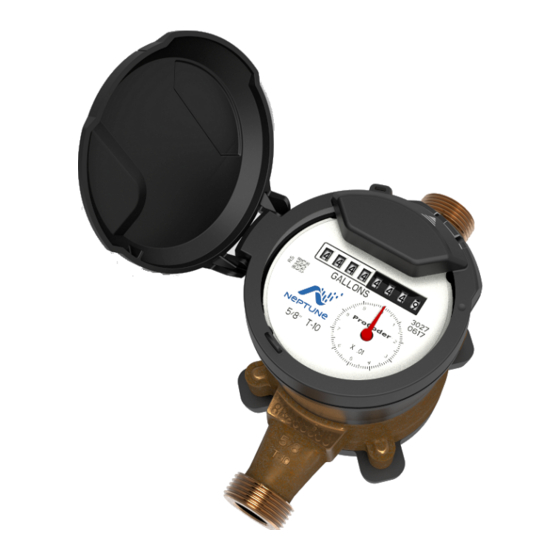
Chapter 1: Product Description Figure 1 – ProCoder™)R900i™ ProCoder™)R900i™ Programming The ProCoder)R900i is NOT field-programmable. At the factory, each of the following items is programmed into the meter interface unit (MIU): Serial number – Each MIU is given a unique serial number / identification number Meter size and change gear information ProCoder™)R900 Installation and Maintenance Guide... -
Page 15: Chapter 2: Specifications
Chapter 2: Specifications This chapter provides the specifications for the ProCoder™)R900i™. Electrical Specifications The ProCoder)R900i is powered by a lithium battery. Transmitter Specifications Table 1 – Transmitter Specifications Specification Description ® Transmit Period Every 14 to 20 seconds (standard R900 mobile message) Every seven and one-half minutes (standard R900 fixed network message) -
Page 16: Dimensions And Weight
Chapter 2: Specifications Dimensions and Weight Table 4 – Dimensions and Weight Measurement Description Dimensions Refer toFigure 2 and Figure 3 on page 5. Weight Inside – 1.39 lbs. (630.5 grams) Pit – 1.62 lbs. (734.8) grams) ProCoder™)R900i™ Dimensions The following diagrams show both the inside and pit dimensions for the ProCoder)R900i. -
Page 17: Figure 3 - Procoder™)R900I™ Antenna Dimensions
Chapter 2: Specifications Figure 3 – ProCoder™)R900i™ Antenna Dimensions ProCoder™)R900 ™ Installation and Maintenance Guide... - Page 18 Chapter 2: Specifications This page intentionally left blank. ProCoder™)R900 ™ Installation and Maintenance Guide...
-
Page 19: Chapter 3: Reading The Procoder™)R900I
Chapter 3: Reading the ProCoder™)R900i™ This chapter provides information on reading the ProCoder™)R900i™. How to Read Become familiar with the information available from the meter. Figure 4 – ProCoder™ Face and Sweep Hand The sensitive sweep hand provides a visual representation of extreme low flows as well as reverse flows. -
Page 20: Common Causes Of Leaks
Chapter 3: Reading the ProCoder™)R900i™ Common Causes of Leaks Leaks can result from various circumstances. The following table contains some common causes of leaks. Table 5 – Possible Leaks Intermittent Continuous Possible Cause of Leak Leak Leak Outside faucet, garden, or sprinkler system leaking Toilet valve not sealed properly Toilet running Faucet in kitchen or bathrooms leaking... -
Page 21: How To Tell If Water Is In Use
Chapter 3: Reading the ProCoder™)R900i™ How to Tell if Water is in Use To determine if water is in use, complete the following steps: 1. View the mechanical sweep hand. 2. Determine the following conditions. If the sweep hand is: Moving slowly in a clockwise direction, water is running very slowly Moving quickly, water is running Not moving, water is not in use... - Page 22 Chapter 3: Reading the ProCoder™)R900i™ This page intentionally left blank. ProCoder™)R900 ™ Installation and Maintenance Guide...
-
Page 23: Chapter 4: Installing The Procoder™)R900I
Chapter 4: Installing the ProCoder™)R900i™ This chapter describes the installation process for the ProCoder™)R900i™. Prior to Installation This section provides information on: Storing and unpacking the ProCoder)R900i Site selection Preliminary tests, tools, and materials needed for installation Complete these procedures before you install the ProCoder. Storage Upon receipt, inspect the shipping containers for damage, and inspect the contents of any damaged cartons prior to storage. -
Page 24: Site Selection
Chapter 4: Installing the ProCoder™)R900i™ Site Selection Installation and operation in moderate temperatures increases reliability and product life. See "Environmental Conditions" on page 3. Follow these guidelines when selecting a location to install the ProCoder)R900i: Install the ProCoder)R900i in a vertical and upright position. Clear the selected location of all obstructions. -
Page 25: Retrofit Meter Installation
Chapter 4: Installing the ProCoder™)R900i™ Use caution; the meter threads are sharp. 4. Place the coupling gaskets inside the coupling nuts and set the meter in the line. Align the meter in a horizontal position with the register dial facing upward. The direction of flow marked on the meter must agree with the direction of actual water flow. -
Page 26: Connecting The Procoder™)R900I ™ Through-The-Lid Antenna
Chapter 4: Installing the ProCoder™)R900i™ Connecting the ProCoder™)R900i ™ Through-the-Lid Antenna When ordering an external antenna for the ProCoder)R900i unit, Neptune recommends at least a 6-foot cable to allow for easy removal of the pit lid when necessary. Figure 6 – ProCoder™)R900i™ Antenna Installing the Antenna To install the antenna, complete the following steps. -
Page 27: Figure 8 - Locking The Nut On The Antenna
Chapter 4: Installing the ProCoder™)R900i™ 2. Thread the locking nut onto the antenna (smooth end towards lid). Figure 8 – Locking the Nut on the Antenna 3. Hand tighten the nut securely to the lid. Figure 9 – Securing the Locking Nut Figure 10 shows a completed installation of the antenna. -
Page 28: Attaching The Antenna To The Miu
Chapter 4: Installing the ProCoder™)R900i™ Attaching the Antenna to the MIU 1. Remove the protective cap and gasket. If you are replacing an existing antenna, remove the existing antenna connection. Clean any dirt, debris, or dielectric grease from the F connector on the MIU housing. Figure 11 –... -
Page 29: Figure 13 - Connecting The Coaxial Cable
Chapter 4: Installing the ProCoder™)R900i™ 3. Push in and turn clockwise until the antenna connector is properly seated on the three-lobed black plastic latch plate. Figure 13 – Connecting the Coaxial Cable ProCoder™)R900 ™ Installation and Maintenance Guide... - Page 30 Chapter 4: Installing the ProCoder™)R900i™ This page intentionally left blank. ProCoder™)R900 ™ Installation and Maintenance Guide...
-
Page 31: Chapter 5: Data Logging Extraction
Chapter 5: Data Logging Extraction This chapter provides information about data logging. About Data Logging The ProCoder™)R900i™ stores interval data for data logging and retrieving this data ® ® through RF activation. You activate the ProCoder)R900i using the Trimble Nomad ®... -
Page 32: Figure 15 - N_Sight™ Menu
Chapter 5: Data Logging Extraction 2. From the HHU Menu screen, click UTILS (option 4). Figure 15 – N_SIGHT™ Menu 3. Click DATA LOGGER (option 9). Figure 16 – Data Logger Option ProCoder™)R900 Installation and Maintenance Guide i™... -
Page 33: Initializing The Data Logger
Chapter 5: Data Logging Extraction 4. Type your reader ID and password (if applicable) for the host software, and then click LOGIN. Figure 17 – Reader ID Input Initializing the Data Logger 1. Verify the time is correct, and then click YES. Figure 18 –... -
Page 34: Figure 19 - Initializing Rf Device
Chapter 5: Data Logging Extraction 2. Click INITIALIZE. Figure 19 – Initializing RF Device 3. Select RF and type the MIU ID. Figure 20 – Entering MIU ID ProCoder™)R900 Installation and Maintenance Guide i™... -
Page 35: Figure 21 - Capture Button
Chapter 5: Data Logging Extraction 4. After you type the MIU ID, click CAPTURE. Figure 21 – Capture Button A prompt appears for you to provide meter size and unit of measure. 5. Type or select the field information, and then click OK. Figure 22 –... -
Page 36: Initiating Rf-Activated Data Logging
Chapter 5: Data Logging Extraction Initiating RF-Activated Data Logging 1. Click START to initiate RF-activated data logging. Figure 23 – Start Button The R900 BCT activates the ProCoder)R900i and listens for the data logger to start transmitting. Figure 24 – Listening for Data ProCoder™)R900 Installation and Maintenance Guide i™... -
Page 37: Figure 25 - Receiving Data
Chapter 5: Data Logging Extraction The screen displays the data received. Figure 25 – Receiving Data 2. After the data logging process is completed, choose the meter size. See Figure 22 on page 23. 3. Click GRAPH to display the data in a graph. See examples of graphs in Figure 27 on page 26. -
Page 38: Sample Data Logging Graphs
Chapter 5: Data Logging Extraction Sample Data Logging Graphs The following are two examples of the graphs produced with data logging. Figure 27 – Examples of Data Logging Graphs Table 6 – Data Logging Graph Legend Color Code Description 1 red bar Intermittent Leak 2 red bars Continuous Leak... -
Page 39: Off-Cycle Data Extraction
Chapter 5: Data Logging Extraction Off-Cycle Data Extraction Off-cycle reads are 96 days of daily reads. This allows the utilities to retrieve move-out reads or monitor vacant usage to prevent theft. To navigate to the off-cycle function, complete the following steps. 1. -
Page 40: Belt Clip Transceiver
Chapter 5: Data Logging Extraction 3. Click OFF CYCLE (option 4). Figure 30 – Off-Cycle Option 4. Type the read ID and the password. 5. Click LOGIN. 6. Confirm the date and time are correct. 7. Click YES. Belt Clip Transceiver To pair the BCT, complete the following steps. -
Page 41: Chapter 6: Troubleshooting
Chapter 6: Troubleshooting This chapter takes you through troubleshooting procedures for the ProCoder™)R900i™. Possible Reading Values This section provides possible reading values and what they indicate. Table 7 – Reading Value Examples Reading Value Definition Troubleshooting Failure to retrieve reading This usually indicates a cut wire. - Page 42 Chapter 6: Troubleshooting This page intentionally left blank. ProCoder™)R900 ™ Installation and Maintenance Guide...
-
Page 43: Chapter 7: Contact Information
Chapter 7: Contact Information Within North America, Neptune Customer Support is available Monday through Friday, 7:00 A.M. to 5:00 P.M. Central Standard Time by telephone, email, or fax. By Phone To contact Neptune Customer Support by phone, complete the following steps. 1. - Page 44 Chapter 7: Contact Information This page intentionally left blank. ProCoder™)R900 ™ Installation and Maintenance Guide...
-
Page 45: Appendix A: Procoder™)R900I™ Flags
Appendix A: ProCoder™)R900i™ Flags This appendix describes the flags associated with the ProCoder™)R900i™. Description of Flags The two tables in this appendix describe the volume represented by the eighth digit by meter size, and the flags the ProCoder)R900i uses. Table 8 – Eighth-Digit Resolution by Meter Size Eighth-Digit Resolution - Register Size Least Significant Digit... -
Page 46: Zero Consumption Flag
Appendix A: ProCoder™)R900i™ Flags Table 10 – Leak Status Flag Leak Status Flag (resets after 35 days) Based on total amount of 15-minute periods recorded in the previous 24-hour period. No leak Eighth digit incremented less than 50 of the 96 15-minute intervals Intermittent leak Eighth digit incremented in 50-95 of the 96 15-minute intervals Continuous leak... -
Page 47: Glossary
Glossary Automated Meter Reading. antenna (pit) The MIU antenna used for pit installations. The belt clip transceiver. FHSS Frequency-hopping spread-spectrum. Hand-Held Unit. inside version The ProCoder)R900i inside version has a laser sealed plastic body. ProCoder™)R900 ™ Installation and Maintenance Guide... - Page 48 Glossary The Liquid Crystal Display (LCD) is the component where the meter reading and value-added icons are displayed. The meter interface unit. Personal Identification Number for technical support. pit version The ProCoder)R900i pit version has a roll-sealed metal body. register read time The default time is 15 minutes for all registers.
- Page 49 Glossary seal pin The small black plastic nail used to secure the ProCoder)R900i to the meter. serial number A unique identification number given to each MIU at the factory. The default value is the last programmed plus one. Custom serial numbers are not available. spud cap Orange caps that are placed on the ends of a meter when shipping.
- Page 50 Glossary This page intentionally left blank. ProCoder™)R900 ™ Installation and Maintenance Guide...
-
Page 51: Index
Index Index faucet bathroom leaks 8 activate, solar panel 7 kitchen leaks 8 air conditioner, leaks 8 antenna 5 garden leaks 8 general description 1 BCT 19, 28 handling, unpack 11 common causes of leaks 8 heat pump, leaks 8 contact customer support 31 heating, leaks 8 coupling... - Page 52 Index leak air conditioner 8 band 1 common causes 8 found 9 safety practices 12 garden 8 serial number 2 heat pump 8 site selection 12 heating 8 specifications hose 8 functional 3 hot water 8 transmitter 3 ice-maker 8 sprinkler system, leak 8 pet feeder 8 storage 11...
- Page 54 ™) IM ProCoder R900 ™ 01.19 Part No. 13707-001 © Copyright 2006-2019, Neptune Technology Group Inc. Neptune is a registered trademark of Neptune Technology Group Inc.
Need help?
Do you have a question about the ProCoder R900i and is the answer not in the manual?
Questions and answers