Emerson Copeland 4MTL-05 Application Manuallines
Stream co2 semi-hermetic compressors for transcritical & subcritical applications
Hide thumbs
Also See for Copeland 4MTL-05:
- Application manuallines (45 pages) ,
- Technical information (2 pages)

Related Manuals for Emerson Copeland 4MTL-05


Summary of Contents for Emerson Copeland 4MTL-05
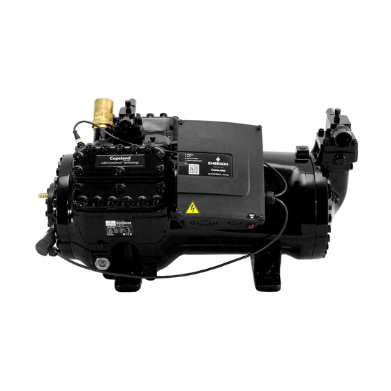
- Page 1 Application Guidelines Copeland Stream CO ™ Semi-Hermetic Compressors for Transcritical & Subcritical Applications 4MTL-05_ to 4MTL-50_ 4MSL-03_ to 4MSL-15_...
-
Page 2: Table Of Contents
About these guidelines ....................1 Safety instructions ................... 1 1.1 Icon explanation ....................... 1 1.2 Safety statements ......................1 1.3 General instructions ......................2 Product description ..................3 2.1 General information about Copeland™ Stream CO semi-hermetic compressors for transcritical and subcritical applications ................... 3 2.2 Nomenclature ........................ - Page 3 Part-winding motors (YY/Y) – Code F ..............18 4.2.2 Star / Delta motors (Y/∆) – Code E ..............18 4.2.3 4.2.4 Terminal box isolators and jumpers position ............19 4.3 Wiring diagrams ......................20 4.3.1 Compressors with Next Generation CoreSense module ........20 4.3.2 Compressors with CoreSense Protection module ..........
-
Page 4: About These Guidelines
Besides the support they provide, the instructions listed herein are also critical for the proper and safe functioning of the compressors. Emerson will not guarantee the performance and reliability of the product if it is misused in regard of these guidelines. -
Page 5: General Instructions
General instructions WARNING System breakdown! Personal injuries! Never install a system in the field and leave it unattended when it has no charge, a holding charge, or with the service valves closed without electrically locking out the system. System breakdown! Personal injuries! Only approved refrigerants and refrigeration oils must be used. -
Page 6: Product Description
Product description General information about Copeland™ Stream CO semi-hermetic compressors for transcritical and subcritical applications These guidelines cover Copeland™ Stream CO semi-hermetic compressors. The Stream CO series of 4MTL* transcritical models ranges from 5 to 50 hp; the series of 4MSL* subcritical models ranges from 3 to 15 hp. -
Page 7: Nomenclature
maximum standstill pressures of 135 bar at high side and 90 bar at low side – see Chapter 3.2.1 "Safety relief valves". Refrigerant flow and heat transfer have been optimized for best performance. NOTE: Throughout these guidelines, pressure values shown with the bar(a) or bar unit are absolute pressures. -
Page 8: Application Range
POE oil. Large models (4MTL-35 to 4MTL-50) can alternatively be delivered on request with PAG oil. Oil recharge values can be taken from Copeland™ brand products Select software available at www.climate.emerson.com/en-gb. Qualified refrigerant R744 (CO Copeland brand... -
Page 9: Recommendations For Minimum Suction Superheat - Lubrication Conditions
Figure 4: Operating envelopes for transcritical applications with R744 – Models 4MTL-30 to 4MTL-50 Figure 5: Operating envelope for subcritical applications with R744 – Models 4MSL-03 to 4MSL-15 2.4.3 Recommendations for minimum suction superheat – Lubrication conditions The operation of CO compressors at conditions where the viscosity of the oil is low might become very harmful with regard to compressor lifetime expectancy. -
Page 10: Design Features
discharge shut-off valve) the temperature is expected to be 15-20 K lower than inside the cylinder head. This fact must be taken into account when applying the values in Table 4 below. Maximum acceptable discharge Minimum Minimum oil temperature Application superheat temperature required... -
Page 11: Oil Level
Compressor Transcritical Lubrication Subcritical Lubrication size mode system mode system 4MTL-05 4MSL-03 Small 4MTL-07 Splasher 4MSL-04 Splasher 4MTL-09 4MSL-06 4MTL-12 4MSL-08 Medium 4MTL-15 Splasher 4MSL-12 Splasher 4MTL-30 4MSL-15 4MTL-35 Large 4MTL-40 Oil pump 4MTL-50 Table 5: Lubrication system on Stream CO compressors 2.5.4 Oil level Small- and medium-size models (4MSL-03 to 4MSL-15, 4MTL-05 to 4MTL-30) are equipped with... - Page 12 More information about this product can be found Figure 11: TraxOil OM5 with sight glass & coil at www.climate.emerson.com/en-gb. 2.5.4.2 Oil level monitoring system OW4/OW5 TraxOil The OW4 and OW5 TraxOil are intended for systems which only require oil level monitoring and alarming and do not need active oil level balancing.
- Page 13 (SPDT) changes into alarm state. The alarm contact may be used to shut down the compressor. The alarm will be reset when the oil level goes back to normal. More information about this product can be found at www.climate.emerson.com/en-gb. AGL_Stream_ST_4MTL_4MSL_E_Rev01...
-
Page 14: Installation
Installation WARNING High pressure! Injury to skin and eyes possible! Be careful when opening connections on a pressurized item. Compressor handling 3.1.1 Delivery Please check whether the delivery is correct and complete. Any deficiency should be reported immediately in writing. Standard delivery: ▪... -
Page 15: Installation Location
Figure 14: Compressor lifting 3.1.4 Installation location Ensure the compressors are installed on a solid level base. Horizontal installation is recommended. Temperatures around the compressor should not exceed 65 °C in order to avoid suction gas temperature increase and malfunctioning of electronics. 3.1.5 Mounting parts To minimize vibration and start/stop impulses flexible mounting should be used. -
Page 16: Pressure Safety Controls
Pressure safety controls 3.2.1 Safety relief valves CAUTION High pressure! System leak! In the event that a pressure relief valve activates repeatedly, check and replace it as needed in order to avoid a permanent leak. Always check system for CO loss after activation of the pressure relief valve. -
Page 17: Maximum Allowable Pressures Ps
Copeland brand products Select software www.climate.emerson.com/en-gb. Shut-off valves Stream CO compressors are factory-equipped with shut-off valves on both the suction and discharge sides. The shut-off valves are suitable for welding and brazing. Suction connection Discharge connection Flange... -
Page 18: Shut-Off Valves Design
Suction connection Discharge connection Flange Displacement Compressor mountings Inner Drawing Inner Drawing (m³/h) Description Description (mm) diameter number diameter number W22 / ODS 5/8 W17.2 / ODS 1/2 4MSL-03 4.60 5/8" 1/2" 510-0823-00 W22 / ODS 5/8 510-0809-00 W17.2 / ODS 1/2 4MSL-04 6.20 45 x 45... -
Page 19: Variations For Shut-Off Valves
Emerson also offers variations for connection sizes – see Tables 9 & For Stream CO 10 below for details. Additionally, a compression fitting can be used for the discharge part of the compressors. -
Page 20: Screens
Variation smaller Ø Compressor Suction connection Discharge connection Flange Displ. Mountings Inner Ø Valve Inner Ø Valve (m³/h) Transcritical Subcritical (mm) brazing description brazing description 4MTL-05 4MSL-03 4.60 W17.2 / W17.2 / 4MTL-07 4MSL-04 6.20 45 x 45 1/2" 1/2" ODS 1/2 ODS 1/2 4MTL-09... -
Page 21: Electrical Connection
Electrical connection General recommendations The compressor terminal box has a wiring diagram on the inside of its cover. Before connecting the compressor, ensure that the supply voltage, the phases and the frequency match the nameplate data. The knockouts have to be removed before the electrical glands can be installed. First make sure that the terminal box is closed with the terminal box cover. -
Page 22: Terminal Box Isolators And Jumpers Position
4.2.4 Terminal box isolators and jumpers position 4.2.4.1 Part-winding motors (AW… or FW…) Part-winding motors can be connected Direct-On-Line or part-winding start. Make sure that the 2 wires (L2) which are guided through the current sensor are in the same direction. The black wire (voltage sensing) from the sensor module must be connected to the same terminal as the wires that are guided through the current sensor. -
Page 23: Wiring Diagrams
Wiring diagrams 4.3.1 Compressors with Next Generation CoreSense module IMPORTANT For small and medium compressor models (4MTL-05 to 4MTL-30 & 4MSL-03 to 4MSL-15), the blue positions 1U, 2V, 3W, 7Z, 8X, 9Y diagrams below must be considered. The position of the terminals in large models (4MTL-35 to 4MTL-50) is inverted and corresponds to the black positions. - Page 24 part) for part-winding and Star/Delta motors (AW… & EW…) 4.3.1.3 Wiring diagram (2 Legend B1 ... Discharge gas sensor DGT .. Discharge gas temperature monitoring B2 ... Oil level watch (TraxOil) OW ..Digital oil level watch B3 ... Oil differential pressure switch (OPS) OPS ..
-
Page 25: Compressors With Coresense Protection Module
4.3.2 Compressors with CoreSense Protection module Wiring diagram for part-winding motors (AW…, FW…) 4.3.2.1 Legend A1 ..CoreSense Protection module K1 ..Contactor M1 A5 ..Terminal box compressor K4 ..Contactor M1 for 2 part-winding F6 ..Fuse for control circuit M21 .. - Page 26 Wiring diagram for Star/Delta motors (EW…) 4.3.2.2 Legend A1 ..CoreSense Protection module K2 ..Contactor M1 Y-connection K3 ..Contactor M1 Δ-connection A5 ..Terminal box compressor F6 ..Fuse for control circuit M21 ..Fan motor / condenser F7 ..
-
Page 27: Compressors With Coresense Diagnostics Module
4.3.3 Compressors with CoreSense Diagnostics module Wiring diagram for part-winding motors (AW…, FW…) 4.3.3.1 Legend A4 ..Sensor module K1 ..Contactor M1 Y-connection A5 ..Compressor terminal box K4 ..Contactor M1 YY-connection CCH ..Crankcase heater L1 ..Current transducer CoreSense F6 .. - Page 28 4.3.3.2 Wiring diagrams for Star/Delta motors (EW…) Legend A4 ..Sensor module L1 ..Current transducer CoreSense A5 ..Compressor terminal box M21 ..Fan motor / condenser F6 ..Fuse for control circuit R2 ..Crankcase heater F7 ..Fuse for control circuit Y7 ..
-
Page 29: Protection Devices
Protection devices Independently from the internal motor protection, fuses must be installed before the compressor. The selection of fuses has to made according to VDE 0635, DIN 57635, IEC 269-1 or EN 60-269-1. Next generation CoreSense™ Next Generation CoreSense™ (or Next Gen CoreSense) is standard in all 4MTL* and 4MSL* Stream semi-hermetic compressors. -
Page 30: Coresense™ Protection
Basic features Motor overheat protection High discharge temperature protection Oil level protection (in combination with Insufficient oil pressure protection Emerson TraxOil) Current protection Phase failure protection Voltage imbalance protection Undervoltage and overvoltage protection Power consumption measurement Part-winding protection Crankcase heater control... -
Page 31: Coresense™ Diagnostics (Until December 2019 Included)
Protection class of the module: IP20. CoreSense™ Diagnostics (until December 2019 included) CoreSense™ Diagnostics was mounted on 4MTL* and 4MSL* Stream compressors up to December 2019 included. Stream compressors with "-D" at the end of the description are equipped with a CoreSense Diagnostics device. -
Page 32: Crankcase Heater
Crankcase heater IMPORTANT Oil dilution! Bearing malfunction! Turn the crankcase heater on 12 hours before starting the compressor. A crankcase heater is used to prevent refrigerant from migrating into the compressor shell during standstill periods. It is always required for 4MTL* and 4MSL* Stream compressors. 4MTL* and 4MSL* Stream compressors use a 100-Watt crankcase heater available in 115 V or 230 V. - Page 33 Remove the plug before heater installation. The crankcase heater is secured into position. Insert the heater in the hole. It is also possible to secure the heater more firmly The mounting ring (preassembled on the by using a rubber hammer on the flat surface. heater before insertion) has to be pressed into the hole.
-
Page 34: Start-Up & Operation
Start-up & operation WARNING Diesel effect! Compressor destruction! The mixture of air and oil at high temperature can lead to an explosion. Avoid operating with air. Leak test As a general rule, the reduction of leaks is a legal obligation. Refrigeration systems must be checked for leakage before they get into operation. -
Page 35: Charging Procedure
Minimum run time Emerson recommends a maximum of 10 starts per hour. The most critical consideration is the minimum run time required to return oil to the compressor after start-up. -
Page 36: Inverter Operation
This phenomenon strongly depends on the system design and operating conditions. Emerson conducted extensive tests to investigate compressor behaviour in terms of resonances. The testing indicates that the following hardware variables have a significant impact on possible resonances: ▪... - Page 37 NOTE: Performance data and envelopes are published in Copeland brand products Select software at www.climate.emerson.com/en-gb. AGL_Stream_ST_4MTL_4MSL_E_Rev01...
-
Page 38: Maintenance & Repair
Since POE holds moisture more readily than mineral oil it is more difficult to remove it through the use of vacuum. Compressors supplied by Emerson contain oil with low moisture content, and it may rise during the system assembling process. Therefore it is recommended that a properly sized filter-drier is installed in all POE systems. -
Page 39: Oil Additives
Figure 40: Oil removal plug location Oil additives Although Emerson cannot comment on any specific product, from our own testing and past experience, we do not recommend the use of any additive to reduce compressor bearing losses or for any other purpose. Furthermore, the long-term chemical stability of any additive in the presence of refrigerant, low and high temperatures, and materials commonly found in refrigeration systems is complex and difficult to evaluate without rigorously controlled chemical laboratory testing. -
Page 40: Appendix 1: Connections Of Stream Co
Appendix 1: Connections of Stream CO compressors 4MTL* 4MSL* 4MTL-05 4MTL-07 4MTL-09 4MSL-03 4MSL-04 4MSL-06 4MTL-12 4MTL-15 4MTL-30 4MSL-08 4MSL-12 4MSL-15 4MTL-35 4MTL-40 4MTL-50 Figure 41 Suction line size (sweat) ID: 5/8" Discharge line size (sweat) ID: 1/2" 4MSL-03, 4MSL-04, 4MSL-06 Tube OD: 4MSL-03, 4MSL-04, 4MSL-06 Tube OD:... -
Page 41: Appendix 2: Tightening Torques In Nm
Appendix 2: Tightening torques in Nm Figure 42: Tightening torques around oil pump M24 X 1.5 3/8" - 16 UNC Pressure relief valve Shut-off valve screws 90 - 110 Nm 36 - 44 Nm LP/HP side Discharge and suction SW 24 mm SA 8 mm Shut-off valve cap 3/4"... - Page 42 Figure 43: Hexagon socket screws (Allen / Inbus) & hexagon heads (Wrench) The ranges of torque values given in this specification are assembly torques. Torque after joint relaxation must be within 15 % of the minimum assembly torque unless re-torque is called for and must not be above 10 % of the maximum assembly torque.
-
Page 43: Appendix 3: Correct T-Plate Isolators Depending On Motor Version & Power Supply
Appendix 3: Correct T-plate isolators depending on motor version & power supply AGL_Stream_ST_4MTL_4MSL_E_Rev01... -
Page 44: Disclaimer
3. Emerson does not assume responsibility for the selection, use or maintenance of any product. Responsibility for proper selection, use and maintenance of any Emerson product remains solely with the purchaser or end user. - Page 45 AGL_Stream_ST_4MTL_4MSL_E_Rev01...
- Page 46 The Emerson logo is a trademark and service mark of Emerson Electric Co. Emerson Climate Technologies Inc. is a subsidiary of Emerson Electric Co. Copeland is a registered trademark and Copeland Scroll is a trademark of Emerson Climate Technologies Inc.. All other trademarks are property of their respective owners.
Need help?
Do you have a question about the Copeland 4MTL-05 and is the answer not in the manual?
Questions and answers
Dlt alarm
A DLT alarm indicates a low oil level condition. It triggers an alarm signal, changes the alarm contact (SPDT) to the alarm state, and may be used to shut down the compressor. The alarm resets when the oil level returns to normal.
This answer is automatically generated