
Related Manuals for Emerson Copeland Stream Digital 4MFD-13X


Summary of Contents for Emerson Copeland Stream Digital 4MFD-13X
- Page 1 Application Guidelines Copeland Stream Digital™ Semi-Hermetic Compressors 4MFD-13X to 4MKD-35X 6MMD-30X to 6MKD-50X...
-
Page 2: Table Of Contents
Safety instructions .................... 1 1.1 Icon explanation ......................... 1 1.2 Safety statements ......................1 1.3 General instructions ......................1 Product description ..................3 2.1 Common information about Copeland Stream Digital™ semi-hermetic compressors ..3 2.2 About these guidelines ....................... 3 2.3 Nomenclature ........................ - Page 3 4.1 General recommendations....................13 4.2 Electrical installation ......................13 Part-winding motors (YY/Y) – Code A ..............13 4.2.1 Star / Delta motors (Y/∆) – Code E ..............13 4.2.2 4.3 Wiring diagrams ....................... 13 Wiring diagrams for part winding motors (AW…) ..........14 4.3.1 Wiring diagrams for Star / Delta motors (EW…) ..........
-
Page 4: Safety Instructions
Safety instructions Copeland™ brand products semi-hermetic compressors are manufactured according to the latest European safety standards. Particular emphasis has been placed on the user’s safety. These compressors are intended for installation in systems according to the Machinery Directive MD 2006/42/EC. They may be put to service only if they have been installed in these systems according to instructions and conform to the corresponding provisions of legislation. - Page 5 CAUTION Contact with POE! Material damage! POE lubricant must be handled carefully and the proper protective equipment (gloves, eye protection, etc.) must be used at all times. POE must not come into contact with any surface or material that it might damage, including without limitation, certain polymers, eg, PVC/CPVC and polycarbonate.
-
Page 6: Product Description
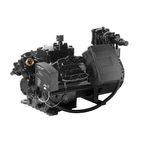
Product description Common information about Copeland Stream Digital™ semi-hermetic compressors These guidelines cover Copeland Stream Digital™ semi-hermetic compressors. The semi- hermetic reciprocating compressor family consists of different ranges. The Stream Digital series of 4M*D and 6M*D models ranges from 13 hp to 50 hp. Medium temperature Low temperature Nominal... -
Page 7: Nameplate Information
Nameplate information All important information for identification of the compressor is printed on the nameplate located below the compressor oil pump. The type of refrigerant used should be stamped on the nameplate by the installer. The year and month of production are shown as a part of the serial number (Jan. = A, Feb. = B, …... -
Page 8: Application Limits
one standard bank; one Digital modulated bank; one capacity-controlled bank (blocked suction std) only for 6M*D. NOTE: To upgrade 6M* compressors to 6M*D, Emerson Climate Technologies recommends to use the central cylinder bank. 2.6.2 Digital theory of operation Digital technology is now available on the 4M*D and 6M*D Stream compressors. - Page 9 Bolts / studs Solenoid valve Solenoid valve gasket Cylinder head Figure 3: Digital modulation components Loaded Unloaded Gas enters the compressor Gas enters the compressor passes through the body passes through the body into the valve plate Unloader mechanism blocks gas Compressed gas before entering the valve plate exits the compressor...
-
Page 10: Digital Control
Due to the high life cycle requirements in a hot gas environment, a special valve has been developed. Due to reliability requirements, only Emerson solenoid valves may be used. All compressor warranties are null and void if the Emerson valve is not used. Solenoid coils will be sold separately for all Stream Digital compressors. -
Page 11: Oil Pumps
In the case of high-powered motors the breakaway starting currents become so large that they lead to disruptive voltage dips in the mains. The compressors that are subject to current limitation must therefore by all means be equipped with starting load reduction to guarantee perfect starting even when the voltages amount to less than approximately 85% of the voltage on the nameplate. -
Page 12: Multiple Compressor Application
2.6.12 Multiple compressor application To ensure smooth and continuous modulation, ie, for optimum suction pressure control, the selection of the Stream Digital and Stream fixed-capacity compressors should be made according to the following rule: - F1 < D - F2 < D+F1 - F3 <... -
Page 13: Installation
Installation WARNING High pressure! Injury to skin and eyes possible! Be careful when opening connections on a pressurized item. Compressor handling 3.1.1 Delivery Please check whether the delivery is correct and complete. Any deficiency should be reported immediately in writing. Standard delivery: ... -
Page 14: Installation Location
In order to avoid refrigerant leaks or other damage the compressors should not be lifted by the service valves or other accessories. 3.1.4 Installation location Ensure the compressors are installed on a solid level base. 3.1.5 Mounting parts To minimize vibration and start/stop impulses flexible mounting should be used. For this purpose one set of spring mounting parts for each of the Stream models is delivered with each 4M*D and 6M*D compressor. -
Page 15: Brazing Procedure
High-pressure side (HP): 28.0 bar(g) (up to S/N 14K46143M) 32.5 bar(g) (from S/N 14K46144M onwards) Low-pressure side (LP): 22.5 bar NOTE: The compressor operating range may be restricted for various reasons. Check the application range limitations in Copeland brand products Select software at www.emersonclimate.eu. -
Page 16: Electrical Connection
Electrical connection General recommendations The compressor terminal box has a wiring diagram on the inside of its cover. Before connecting the compressor, ensure the supply voltage, the phases and the frequency match the nameplate data. The knockouts have to be removed before the electrical glands can be installed. First make sure that the terminal box is closed with the terminal box cover. -
Page 17: Wiring Diagrams For Part Winding Motors (Aw
4.3.1 Wiring diagrams for part winding motors (AW…) Part-winding motors can be connected Direct-on-line or part-winding start. NOTE: The sensor module inside the terminal box requires a separate 24V AC power supply. Part-winding start Direct-on-line start First start step 1-2-3 Y –... - Page 18 4.3.1.2 Compressors with CoreSense Protection module Legend A1 ..CoreSense Protection module K4 ..Contactor M1 for second part-winding A2 ..OPS2 Oil pressure switch M21 ..Fan motor / condenser A5 ..Compressor terminal box R2 ..Crankcase heater F6 ..
-
Page 19: Wiring Diagrams For Star / Delta Motors (Ew
4.3.2 Wiring diagrams for Star / Delta motors (EW…) Star / Delta motors can be connected Direct-on-line or Star / Delta start. NOTE: The sensor module inside the terminal box requires a separate 24V AC power supply. Star / Delta start Direct-on-line start Direct-on-line start ∆... -
Page 20: Protection Devices
4.3.2.2 Compressors with CoreSense Protection module Legend A1 ..CoreSense Protection module K2 ..Contactor M1 Y-connection K3 ..Contactor M1 Δ-connection A2 ..OPS2 Oil pressure switch A5 ..Compressor terminal box M21 ..Fan motor / condenser F6 ..Fuse for control circuit R2 .. - Page 21 module is capable of communication via Modbus® protocol. An external overload protection is not necessary. Discharge temperature Sensor Module Current Sensor Sensor CoreSense Control Module Oil Pressure Sensor Motor Temperature Sensor (PTC) Figure 17: CoreSense Diagnostics module For the electrical connection of the CoreSense Diagnostics module, please refer to the wiring diagram below: Figure 18: CoreSense Diagnostics module wiring diagram C6.3.2/0416-0716/E...
-
Page 22: Coresense™ Protection
NOTE: For more information please refer to Technical Information D7.8.4 "CoreSense™ Diagnostics for Stream refrigeration compressors". CoreSense™ Protection 4.6.1 Motor protection Stream Digital compressors with "-P" at the end of the description are equipped with a CoreSense Protection device. The temperature-dependent resistance of the thermistor (also PTC-resistance) is used to sense the winding temperature. - Page 23 Where there is a 5-wire cable connection between the electrical control panel and the compressor terminal box to the OPS module, the same wires can be applied to the OPS2 which will give the functions of an OPS1 module. To obtain use of all of the features of the OPS2 a 7-wire cable between the electrical control cabinet and the compressor terminal box should be used.
-
Page 24: Crankcase Heater
Crankcase heater IMPORTANT Oil dilution! Bearing malfunction! Turn the crankcase heater on 12 hours before starting the compressor. A crankcase heater is used to prevent refrigerant migrating into the shell during standstill periods. Heaters for 4M*D and 6M*D compressors are screwed into a sleeve (see Figure 22). The crankcase heater is available in 120V, 230V and 480V. -
Page 25: Starting Up & Operation
Starting up & operation WARNING Diesel effect! Compressor destruction! The mixture of air and oil at high temperature can lead to an explosion. Avoid operating with air. Leak test The suction shut-off valve and discharge shut-off valve on the compressor must remain closed during pressure testing to prevent air and moisture from entering the compressor. -
Page 26: Initial Start-Up
Minimum run time Emerson Climate Technologies recommends a maximum of 10 starts per hour. The most critical consideration is the minimum run time required to return oil to the compressor after start-up. Pump-down In systems that require a compressor pump-down, special attention should be paid to the control logic for the Digital unloader coil. -
Page 27: Maintenance & Repair
Compressors supplied by Emerson Climate Technologies contain oil with low moisture content, and it may rise during the system assembling process. Therefore it is recommended that a properly sized filter-drier is installed in all POE systems. -
Page 28: Oil Additives
Oil additives Although Emerson Climate Technologies cannot comment on any specific product, from our own testing and past experience, we do not recommend the use of any additives to reduce compressor bearing losses or for any other purpose. Furthermore, the long term chemical... -
Page 29: Appendix 1: Stream Digital Compressor Connections
Appendix 1: Stream Digital compressor connections 4M*D 4MFD-13X 4MLD-15X 4MMD-20X 4MTD-22X 4MUD-25X 4MAD-22X 4MHD-25X 4MID1-30X 4MJD-30X 4MKD-35X Discharge line size (sweat) Suction line size (sweat) 4MFD-13X, 4MLD-15X, 4MFD-13X, 4MLD-15X, Ø 1 5/8" Ø 1 1/8" 4MAD-22X, 4MMD-20X, 4MAD-22X 4MHD-25X, 4MID-30X Suction line size (sweat) Discharge line size (sweat) 4MMD-20X, 4MHD-25X,... -
Page 30: Appendix 2: Tightening Torques In Nm
3. Emerson does not assume responsibility for the selection, use or maintenance of any product. Responsibility for proper selection, use and maintenance of any Emerson product remains solely with the purchaser or end user. - Page 31 Tel. +49 (0) 2408 929 0 - Fax: +49 (0) 2408 929 570 - Internet: www.emersonclimate.eu The Emerson Climate Technologies logo is a trademark and service mark of Emerson Electric Co. Emerson Climate Technologies Inc. is a subsidiary of Emerson Electric Co.
Need help?
Do you have a question about the Copeland Stream Digital 4MFD-13X and is the answer not in the manual?
Questions and answers