Emerson Copeland Stream 4MF-13X Application Manuallines
Semi-hermetic compressors
Hide thumbs
Also See for Copeland Stream 4MF-13X:
- User manual (36 pages) ,
- Application manuallines (44 pages)

Related Manuals for Emerson Copeland Stream 4MF-13X


Summary of Contents for Emerson Copeland Stream 4MF-13X
- Page 1 Application Guidelines Copeland Stream™ Semi-Hermetic Compressors 4MF-13X to 4MK-35X & 6MM-30X to 6MK-50X...
-
Page 2: Table Of Contents
Safety instructions .................... 1 1.1 Icon explanation ......................... 1 1.2 Safety statements ......................1 1.3 General instructions ......................1 Product description ..................3 2.1 Common information about Copeland Stream™ semi-hermetic compressors ....3 2.2 About these guidelines ....................... 3 2.3 Nomenclature ........................3 2.4 Nameplate information ....................... - Page 3 4.3 Wiring diagrams ....................... 10 Wiring diagram for part-winding motors (AW…) ..........11 4.3.1 Wiring diagram for Star / Delta motors (EW…) ............ 13 4.3.2 4.4 Protection devices ......................15 4.5 CoreSense™ Diagnostics ....................15 4.6 CoreSense™ Protection ....................16 4.6.1 Motor protection ....................
-
Page 4: Safety Instructions
Safety instructions Copeland™ brand products semi-hermetic compressors are manufactured according to the latest European safety standards. Particular emphasis has been placed on the user’s safety. These compressors are intended for installation in systems according to the Machinery Directive MD 2006/42/EC. They may be put to service only if they have been installed in these systems according to instructions and conform to the corresponding provisions of legislation. - Page 5 CAUTION Contact with POE! Material damage! POE lubricant must be handled carefully and the proper protective equipment (gloves, eye protection, etc.) must be used at all times. POE must not come into contact with any surface or material that might be harmed by POE, including without limitation, certain polymers, eg,.
-
Page 6: Product Description
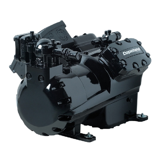
Product description Common information about Copeland Stream™ semi-hermetic compressors These guidelines cover Copeland Stream™ semi-hermetic compressors. The semi-hermetic reciprocating compressor family consists of different ranges. The Stream™ series of 4M* and 6M* models ranges from 13 hp to 50 hp. High temperature Medium temperature Low temperature... -
Page 7: Nameplate Information
Nameplate information All important information for identification of the compressor is printed on the nameplate located below the compressor oil pump. The type of refrigerant used should be stamped on the nameplate by the installer. Figure 1 The year and month of production are shown as part of the serial number (Jan = A, Feb = B, … Dec = L). -
Page 8: Application Limits
2.5.2 Application limits For application envelopes please refer to Copeland brand products Select software at www.emersonclimate.eu. Design features 2.6.1 Compressor construction All compressors are fitted with Stream valve plates which cannot be dismantled. To maintain the high capacity of these compressors in case of exchange, the correct valve-plate-to-body gasket must always be selected. -
Page 9: Oil Pumps
2.6.6 Oil pumps The oil pumps used for Stream compressors are independent of their rotating direction. On compressors delivered with CoreSense™ Diagnostics (-D), the oil pump integrates the electronic switch for integrating oil pressure safety functionality. Compressors with CoreSense™ Protection (-P) are designed to accommodate fittings for an OPS2, FD-113ZU, or Sentronic oil safety system or a standard oil pressure switch (OPS2 oil sensor included in the oil pump). -
Page 10: Installation
Installation WARNING High pressure! Injury to skin and eyes possible! Be careful when opening connections on a pressurized item. Compressor handling 3.1.1 Delivery Please check whether the delivery is correct and complete. Any deficiency should be reported immediately in writing. Standard delivery: ... -
Page 11: Installation Location
In order to avoid refrigerant leaks or other damage the compressors should not be lifted by the service valves or other accessories. 3.1.4 Installation location Ensure the compressors are installed on a solid level base. 3.1.5 Mounting parts To minimize vibration and start/stop impulses flexible mounting should be used. For this purpose one set of spring mounting parts for each of the Stream models is delivered with each 4M* and 6M* compressor. -
Page 12: Brazing Procedure
NOTE: The compressor operating range may be restricted for various reasons. Check the application range limitations in Copeland brand products Select software at www.emersonclimate.eu. Brazing procedure IMPORTANT Blockage! Compressor breakdown! Maintain a flow of oxygen-free nitrogen through the system at very low pressure during brazing. Nitrogen displaces the air and prevents the formation of copper oxides in the system. -
Page 13: Electrical Connection
Electrical connection General recommendations The compressor terminal box has a wiring diagram on the inside of its cover. Before connecting the compressor, ensure that the supply voltage, the phases and the frequency match the nameplate data. The knockouts have to be removed before the electrical glands can be installed. First make sure that the terminal box is closed with the terminal box cover. -
Page 14: Wiring Diagram For Part-Winding Motors (Aw
4.3.1 Wiring diagram for part-winding motors (AW…) Part winding motors can be connected direct-on-line or part-winding start. NOTE: The sensor module inside the terminal box requires a separate 24V AC power supply. Part-winding start Direct-on-line start First start step 1–2-3 Y - Y Y - Y Part-winding motor:... - Page 15 4.3.1.2 Compressors with CoreSense Protection module Legend A1 ..CoreSense Protection module K1 ..Contactor M1 A2 ..OPS2 Oil pressure switch K4 ..Contactor M1 for second part-winding A5 ..Compressor terminal box M21 ..Fan motor / condenser F6 ..
-
Page 16: Wiring Diagram For Star / Delta Motors (Ew
4.3.2 Wiring diagram for Star / Delta motors (EW…) Star / Delta motors can be connected direct-on-line or Star / Delta start. NOTE: The sensor module inside the terminal box requires a separate 24V AC power supply. Direct-on-line start Direct-on-line start Star / Delta start ∆... - Page 17 4.3.2.2 Compressors with CoreSense Protection module Legend A1 ..CoreSense Protection module K1 ..Contactor M1 A2 ..OPS2 Oil pressure switch K2 ..Contactor M1 Y-connection K3 ..Contactor M1 Δ-connection A5 ..Compressor terminal box F6 ..Fuse for control circuit M21 ..
-
Page 18: Protection Devices
Protection devices Independently from the internal motor protection, fuses must be installed before compressor start-up. The selection of fuses has to be carried out according to VDE 0635, DIN 57635, IEC 269-1 or EN 60-269-1. CoreSense™ Diagnostics CoreSense™ Diagnostics is used for all 4M* and 6M* Stream semi-hermetic compressors. It combines oil and motor protection in one module, replacing OPS1/2 and the electronic module INT69TM. -
Page 19: Coresense™ Protection
For the electrical connection of the CoreSense Diagnostics module, refer to the wiring diagram below: Figure 14: CoreSense module wiring diagram NOTE: For more information please refer to Technical Information D7.8.4 "CoreSense™ Diagnostics for Stream refrigeration compressors". CoreSense™ Protection 4.6.1 Motor protection Stream compressors with "-P"... -
Page 20: Oil Pressure Control
4.6.2 Oil pressure control The oil pressure switch breaks the control circuit when the pressure difference between the oil pump outlet and the crankcase is too low. The switch must be properly adjusted and tamper- proof. If the oil differential pressure drops below the minimum acceptable value the compressor will be stopped after a 120-second delay. -
Page 21: Crankcase Heaters
Mechanical oil pressure switch – ALCO FD-113ZU (A22 - 057) 4.6.2.2 Specifications for electro-mechanical oil pressure switches are as follows: Cut-out pressure: 0.63 ± 0.14 bar Cut-in pressure: 0.9 ± 0.1 bar Time delay: 120 ± 15 sec. The Alco Control FD-113ZU mechanical oil pressure switch operates with the above set points. -
Page 22: Starting Up & Operation
Starting up & operation WARNING Diesel effect! Compressor destruction! The mixture of air and oil at high temperature can lead to an explosion. Avoid operating with air. Leak test The suction shut-off valve and discharge shut-off valve on the compressor must remain closed during pressure testing to prevent air and moisture from entering the compressor. -
Page 23: Initial Start-Up
MUST NOT be started, nor may high-potential testing be carried out under vacuum. Minimum run time Emerson Climate Technologies recommends a maximum of 10 starts per hour. The most critical consideration is the minimum run time required to return oil to the compressor after start-up. -
Page 24: Maintenance & Repair
Compressors supplied by Emerson Climate Technologies contain oil with low moisture content, and it may rise during the system assembling process. Therefore it is recommended that a properly sized filter-drier is installed in all POE systems. -
Page 25: Oil Additives
Oil additives Although Emerson Climate Technologies cannot comment on any specific product, from our own testing and past experience, we do not recommend the use of any additive to reduce compressor bearing losses or for any other purpose. Furthermore, the long-term chemical... -
Page 26: Appendix 1: Stream Compressor Connections
Appendix 1: Stream compressor connections 4MF-13X 4ML-15X 4MM-20X 4MT-22X 4MU-25X 4MA-22X 4MH-25X 4MI-30X 4MJ-30X 4MK-32X Discharge line size (sweat) Suction line size (sweat) Ø 1 5/8" 4MF13X, 4ML15X, 4MA22X, Ø 1 1/8" 4MF13X, 4ML15X, 4MA22X 4MM20X, 4MH25X, 4MI30X Suction line size (sweat) Discharge line size (sweat) 4MM20X, 4MH25X, 4MI30X, Ø... -
Page 27: Appendix 2: Tightening Torques In Nm
3. Emerson does not assume responsibility for the selection, use or maintenance of any product. Responsibility for proper selection, use and maintenance of any Emerson product remains solely with the purchaser or end user. - Page 28 Tel. +49 (0) 2408 929 0 - Fax: +49 (0) 2408 929 570 - Internet: www.emersonclimate.eu The Emerson Climate Technologies logo is a trademark and service mark of Emerson Electric Co. Emerson Climate Technologies Inc. is a subsidiary of Emerson Electric Co.
Need help?
Do you have a question about the Copeland Stream 4MF-13X and is the answer not in the manual?
Questions and answers