
Related Manuals for Eaton DSII Series


Summary of Contents for Eaton DSII Series
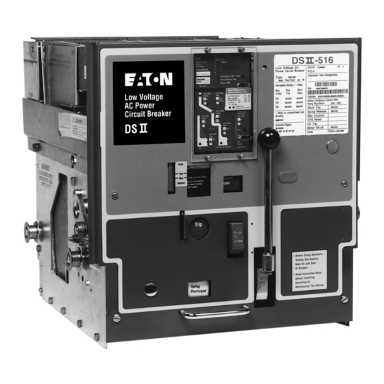
- Page 1 Effective July 2010 Supersedes July 1997 Instructional Book IB694C694-03 IB694C694-02 Instructions for Installation, Operation and Maintenance of Low Voltage Power Circuit Breakers Types DSII and DSLII...
- Page 2 All possible contingencies which may arise during installation operation or maintenance, and all details and variations of this equipment do not purport to be covered by these instructions. If further information is desired by purchaser regarding his particular installation, operation or maintenance of particular equipment, contact the local Eaton representative. eaton corporation www.eaton.com...
-
Page 3: Table Of Contents
3-10.5 Latch Check Switch .....................26 3-10.6 Auxiliary Switch ......................26 3-10.7 Undervoltage Trip Attachment (UVTA) .................26 3-10.8 Overcurrent Trip Switch ....................27 3-11 Miscellaneous Details ......................27 3-11.1 Interference Interlock ....................27 3-11.2 Ground Contact ......................28 3-11.3 Close Bar Guard ......................28 3-11.4 Operation Counter ........................28 eaton corporation www.eaton.com... - Page 4 5-5.1 Trip Latch Overlap Adjustment ..................56 5-5.2 Breaker Open Position Stop Adjustment (DSII-632 Only) ..........56 5-5.3 Moving Contact Adjustment ..................58 5-5.4 Levering Mechanism Adjustment .................58 Lubrication ..........................59 5-6.1 Lubrication Frequency ....................59 5-6.2 Lubrication Location ......................59 SECTION 6: RENEwAL PARTS General ..........................62 eaton corporation www.eaton.com...
- Page 5 4-14 Close Interlock Preventing Efforts to Close Already Closed Breaker ........46 4-15 Padlock Device (Locked Trip-Free with Shutter Raised) ............47 4-16 DSLII-516 Circuit Breaker (Side View) .................. 48 4-17 Blown Limiter Indicator ......................50 4-18 DSII-FT32 Fuse Truck (Front View) ..................50 eaton corporation www.eaton.com...
- Page 6 Type DSII Breaker Ratings ........................ 8 Type DSLII Breaker and Combination Ratings .................. 9 Circuit Breaker and Fuse Truck Weights ..................11 Compatible Circuit Breakers and Compartments ................28 Sensor and Limiter Ratings ......................48 Lubrication Frequency ........................59 eaton corporation www.eaton.com...
-
Page 7: Section 1: Introduction
DSLII breakers have integrally mounted, series connected current limiters. The purpose of the current limiters is to extend the interrupting rating of the standard DSII breaker (Figure 1-3). DSII-840 DSII-632 DSII-308 Figure 1-1 Type DSII Circuit Breaker Family eaton corporation www.eaton.com... -
Page 8: Safety Features
130,000 85,000 85,000 85,000 85,000 85,000 Maximum voltages at which the interrupting ratings apply are: System Voltage Maximum Voltage 208 or 240 Also short-time ratings. Short circuit ratings of non-automatic breakers except the DSII-840/850 which is 65,000. eaton corporation www.eaton.com... -
Page 9: Qualified Personnel
DSII-632 breaker and DSII-FT32 drawout fuse truck in separate interlocked compartments. l DSII-840 breaker and DSII-FT40 drawout fuse truck in separate interlocked compartments. m Maximum continuous rating limited to 3000A when fuse truck compartment is above breaker compartment. eaton corporation www.eaton.com... - Page 10 Instructional Book IB694C694-03 Effective July 2010 Figure 1-3 Type DSLII Breaker with Integral Current Limiters Figure 1-4 DSII Breaker Shown on Compartment’s Captive Extension Rails eaton corporation www.eaton.com...
-
Page 11: Section 2: Receiving, Handling And Installation
(Figure 2-1). ing the transportation phase. Record any observed damage for reporting to the transportation carrier and Eaton, once Table 2.1 Circuit Breaker and Fuse Truck weights the inspection is completed. All reports and claims should be... -
Page 12: Breaker Inspection
NTERPHASE BARRIERS ASSIST IN MAINTAINING PROPER CLEAR- ANCES AND MUST BE IN PLACE AT ALL TIMES DURING CIRCUIT BREAkER OPERATION WITHIN A BREAkER COMPARTMENT. Figure 2-1 DSII Breaker with Lifting Yoke Installed Figure 2-2 DSII Breaker with One Interphase Barrier Removed eaton corporation www.eaton.com... -
Page 13: Levering Circuit Breaker
Push-To- Trip button on the front of the breaker and depressing the shutter (Figure 3-3). Figure 2-3 DSII Breaker with One Arc Chute Removed Figure 2-4 DSII Levering Device Arm Shown in REMOVE Position eaton corporation www.eaton.com... -
Page 14: Drawout Dummy Element
The breaker stabs have holes for bolting to primary bus con- nections. Rear mounted terminal blocks serve as secondary contacts. The basic breaker frame is modified to permit the fixed breaker to be mounted on a panel (Figure 2-5). eaton corporation www.eaton.com... -
Page 15: Section 3: Equipment Description
Interphase Barrier Arc Chutes Secondary Disconnects Main Disconnect Levering Device Arm Metal Faceplate Trip Unit Emergency Charge Handle Trip Unit Sensors Figure 3-1 Type DSII Circuit Breaker (Front and Rear Views) eaton corporation www.eaton.com... -
Page 16: Type Dslii (Limiter) Circuit Breaker
(2) exceed the withstand and interrupting ratings of downstream circuit components. Blown Limiter Indicators Current Limiter Secondary Disconnects Main Disconnect Isolating Transformer Trip Unit Sensor Arc Chute Figure 3-2 Type DSLII Circuit Breaker (Front and Rear Views) eaton corporation www.eaton.com... -
Page 17: Basic Breaker Assembly
WITHIN THE SYSTEM COULD OCCUR, RESULTING IN EQUIPMENT disconnect contact fingers vary with the frame size. A strong DAMAGE, BODILY INJURY AND/OR DEATH. and rigid insulating link operates the moving contact blade assembly. eaton corporation www.eaton.com... -
Page 18: 3-4.2 Primary Stationary Contact Assembly
Each ously described moving arcing contact wedges the station- barrier is held firmly in place by its positioning in the circuit breaker, with no fastener of any type required (Figure 3-8). eaton corporation www.eaton.com... - Page 19 Pivot Block Spring Main Contact Spring Insulating Link Adjusting Nut Hinge Spring Insulating Link Figure 3-4 Type DSII-308 Pole Unit Assembly (Front View) Upper Terminal Lower Terminal (Sensor Removed) Figure 3-5 Type DSII-308 Pole Unit Assembly (Rear View) eaton corporation www.eaton.com...
-
Page 20: Ion Arc Chutes (Interrupter Assemblies)
For more detailed information arc-resistant glass polyester plates. These plates produce about the specific trip unit used with Types DSII and DSLII turbulence in the exhaust gases above the steel plates, and eaton corporation www.eaton.com... - Page 21 (600 Ohms Current Nominal Sensor Resistance) Typical Digitrip RMS III Trip Unit Assembly Typical DSII Type Circuit Breaker Sensors ** Alternate ground locations may be required to meet installation requirements Figure 3-10 Typical Type DSII Tripping System Diagram eaton corporation www.eaton.com...
-
Page 22: Electronic Trip Unit
(Figure 3-11). The actuator is comprised of a permanent Pole Shaft Lever Trip Breaker Shaft Open DTA Plunger DTA Reset Lever Trip Shaft Lever Breaker Actuator Closed Frame Tripped Untripped Actuator Reset Figure 3-11 Type DSII Trip Actuator eaton corporation www.eaton.com... -
Page 23: Operating Mechanism
Indicator Mechanism Frame Trip Latch Reset Spring Roller Manual Charge Main Drive Constraining Link Link R.H. Close R.H. Spring Spring REAR Crank Arm FRONT (Close Springs Removed) Figure 3-12 Typical Front/Rear Views of Manual Spring Charge Mechanism eaton corporation www.eaton.com... -
Page 24: 3-8.2 Power Operated Circuit Breaker
(Figure 3-3). upon the current rating of the breaker. Finger clusters attach to the primary studs of the breaker’s pole unit assembly. Finger clusters can be easily removed using a finger cluster removal tools. eaton corporation www.eaton.com... -
Page 25: Standard And Optional Devices
The spring release coil is energized through the anti-pump relay, the motor cut-off switch, and a normally closed “b” auxiliary switch contact, which operates the spring release latch to release the closing springs. eaton corporation www.eaton.com... -
Page 26: 3-10.5 Latch Check Switch
The result is power operated breakers. that the trip shaft rotates clockwise and trips the breaker. eaton corporation www.eaton.com... -
Page 27: 3-10.8 Overcurrent Trip Switch
(Table 3.1). An interference interlock Tripping by the trip plate, shunt trip device, undervoltage trip bracket is standard on all drawout circuit breakers. device and other such methods does not cause it to operate. eaton corporation www.eaton.com... -
Page 28: 3-11.2 Ground Contact
(Figure DSLII-620 DSLII-620 3-3). The counter is linkage connected to the pole shaft. Actuator Cam Normal Position Overcurrent Trip Indication Position Figure 3-20 Close Bar Guard Shown Installed Figure 3-19 Overcurrent Trip Switch Operation eaton corporation www.eaton.com... -
Page 29: Section 4: Basic Operating Instructions
(Figure 3-3). An optional closing spring release device can be supplied for this same purpose. Refer to paragraph 3-10.2 for additional information. Figure 4-1 Manual Charging of Breaker Closing Springs eaton corporation www.eaton.com... -
Page 30: Power Circuit Breaker Operation
The length of tripped open. This results in the springs loading the associ- this charging handle is significantly shorter than its manual ated bearings and latches for long periods. In addition, an eaton corporation www.eaton.com... -
Page 31: 4-2.1 Spring Charge Mechanism For Power Operated Breakers
(Figure 3-3). Power operated circuit breaker can be opened manually or electrically. Refer to paragraph 3-8.2 for details. eaton corporation www.eaton.com... - Page 32 Spring Release Latch Emergency Charge Device Moving Contact Assembly Spring Release Device Crank Arm Insulating Link Oscillator Pawl Closing Spring Main Drive Link Figure 4-4 Principal Parts in Power Operated Mechanism (Close Spring Shown in Charged Position) eaton corporation www.eaton.com...
- Page 33 Motor Cut-Off Switch Cam Hold Pawl Mechanism Side Frame, Right Hand Crank Shaft Oscillator Mechanism Side Frame, Left Hand Closing Spring Spacers (3) Crank Arm Stop Bracket Figure 4-5 Crank Shaft Assembly Front View (Some Parts Omitted for Clarity) eaton corporation www.eaton.com...
- Page 34 Close Cam Oscillator Pawl Oscillator Bushing Pawl Lifter Oscillator Oscillator Spring Crank Arm Drive Plate Closing Spring Spring End Motor Crank Roller Crank Shaft Ratchet Wheel Ratchet Wheel Pin Hold Pawl Figure 4-6 Power Operated Spring-Charge Details eaton corporation www.eaton.com...
-
Page 35: 4-2.2 Power Operation
The springs are released to close the breaker. When the breaker closes, the “b” contact opens to cut off the spring release coil (SR) and motor (MOT), and the limit switch (LS) contacts reset. eaton corporation www.eaton.com... - Page 36 Breaker Open - Spring Charged (Spring Charged Position Mechanism Side Frame Corresponding to this Closing Cam Position Shown in Fig. 4-2). Hardened Latch Surfaces Figure 4-7 Four Basic Positions of Breaker and Linkage (Enlarged View of Trip Shaft) eaton corporation www.eaton.com...
-
Page 37: Opening (Tripping) Mechanism
The link- age is then in the position shown in Figure 4-7c. The close cam has rotated approximately 180 degrees. eaton corporation www.eaton.com... - Page 38 When Viewed From Front of Breaker (LS Contacts) N.C. Contacts Open When Closing Springs are Fully Charged N.O. Contacts Close When Springs are Fully Charged AUXILIARY SWITCH Figure 4-9 Basic Schematic and Connection Diagrams for Power Operated Breaker eaton corporation www.eaton.com...
- Page 39 5. Undervoltage Trip Attachment (Refer to Paragraph 3-10.7) should be avoided. Indicator Index Tab Front Panel Levering Worm Shaft Levering Worm Indicator Pivot Pin Traveling Stop Nut Traveling Stop Nut Clamp Indicator Lever Levering Worm Gear Levering Shaft Figure 4-10 Drawout Unit Position Indicator eaton corporation www.eaton.com...
-
Page 40: Mechanical Interlocking System Description
4. The breaker can be withdrawn from the compartment by direct pull. The levering device is not engaged with the cradle at this point. 5. The levering device arms are in a horizontal position with their rollers pointing toward the rear (Figure 2-4). eaton corporation www.eaton.com... - Page 41 Pole Shaft Levering Device Shaft Trip Shaft Trip Shaft Pin Tripping Tab Trip Plate Trip Plate Hook Levering Device Crank Handle b. Shutter, Trip Plate Held in Tripped Position Figure 4-11 Shutter, Trip Plate and Trip Shaft Relationship eaton corporation www.eaton.com...
-
Page 42: 4-5.4 Connect Position
1. IN THIS POSITION, DO NOT ATTEMPT TO ELECTRICALLY the CONNECT and TEST positions the cam CHECK THE ELECTRONIC TRIP DEVICE WITH A TEST KIT OR ANY OTHER METHOD, SINCE THE BREAKER WILL BE TRIPPED AND CAUSE A DISRUPTION OF SERVICE. eaton corporation www.eaton.com... - Page 43 Disconnect Position a. Connect Position d. Remove Position Levering Device Arms b. Test Position Shutter Shutter Interlock Pin Interlock Cam Figure 4-12 Shutter, Interlock Cam and Levering Device Arms Relationship eaton corporation www.eaton.com...
-
Page 44: 4-5.6 Spring Discharge Interlock
If the interlock screw is in place in the narrow slot, the interlock plate has practically no play and is forced to rotate exactly as much as the levering device rotates. eaton corporation www.eaton.com... - Page 45 Interlock Plate Assembly Pin “A” Drive Pin Pin “B” Interlock Screw Close Bar Levering Device Shaft Close Bar Pivot Narrow Slot Close Bar Cam Wide Slot Levering Device Arm Figure 4-13 Close-Release Interlock to Discharge Springs on Levering Out eaton corporation www.eaton.com...
-
Page 46: 4-5.10 Padlocking Provision
Bell Crank Pivot Pin Open-Close Indicator Pin Bell Crank Close-Par Cam Spring Released Latch Link Spring Release Device Spring Release Latch Link Pin Closing Cam Stop Roller Close Bar Figure 4-14 Close Interlock Preventing Efforts to Close Already Closed Breaker eaton corporation www.eaton.com... -
Page 47: Dslii Circuit Breaker And Fuse Truck
Shutter Levering Device Worm Shaft Projection on Shutter Bent Tab on Padlock Plate Projection on Trip Plate Padlock Interlock Lever Pin on Padlock Interlock Lever Trip Shaft Figure 4-15 Padlock Device (Locked Trip-Free with Shut- ter Raised) eaton corporation www.eaton.com... -
Page 48: 4-6.1 Dslii Current Limiters
It also insures that circuit breakers (Figure 4-18 and 4-19). the circuit breaker will be tripped when any current limiter has blown. This prevents single phase power from being ap- plied to a three-phase load (Figure 4-17). eaton corporation www.eaton.com... -
Page 49: 4-6.4 Fuse Truck Installation And Use
This is a relatively uncom- closed. plicated procedure on the DSII-FT40 fuse truck, because there is sufficient working space within the truck. Since the eaton corporation www.eaton.com... - Page 50 Indicator Levering Shaft Reset Button Breaker Tripped Position Trip Shaft Figure 4-17 Blown Limiter Indicator Figure 4-18 DSII-FT32 Fuse Truck (Front View) Figure 4-19 DSII-FT32 Fuse Truck (Rear View) Figure 4-20 DSII-FT32 Fuse Truck (Front Cover Removed) eaton corporation www.eaton.com...
-
Page 51: Section 5: Inspection And Maintenance
It is recommended that maintenance record sheets be com- pleted for the equipment. Careful and accurate documenta- tion of all maintenance activities provides a valuable histori- cal reference on equipment condition over time. eaton corporation www.eaton.com... -
Page 52: 5-4.1 Dsii-308 Through Dsii-620 Inspection
Removal of dimension (A) between the stationary arcing contacts and the center section of the cage. If this dimension is not .02 inches or greater, the stationary arcing contacts should be replaced. eaton corporation www.eaton.com... -
Page 53: 5-4.5 Arc Chutes
Close the circuit breaker sion. and check “A” dimensions. The “A” dimensions should be Dimension C Dimension A .020 Minimum Both Sides Breaker Closed Breaker Open These Faces Parallel Breaker Closed Breaker Open Figure 5-1 DSII-308 Contacts and Adjustments eaton corporation www.eaton.com... -
Page 54: 5-4.6 Power Operated Mechanism
The parts Dimension A Dimension C .020 Minimum Both Sides These Faces Parallel Breaker Closed Breaker Open Figure 5-2 DSII-516/620 Contacts and Adjustments eaton corporation www.eaton.com... -
Page 55: Dsii-632 Contacts And Adjustments
5-5.3. the breaker. Dimension C Dimension A .020 Minimum Both Sides Breaker Closed Breaker Open Pin X Pin X Breaker Closed Breaker Open Figure 5-3 DSII-632 Contacts and Adjustments eaton corporation www.eaton.com... -
Page 56: 5-5.1 Trip Latch Overlap Adjustment
2. Slowly rotate the adjusting screw clockwise until the but will stay put. breaker trips. This is the “no overlap” position. Dimension A Dimension C .020 Minimum Both Sides Pin X Pin X Breaker Closed Breaker Open Figure 5-4 DSII-840/850 Contacts and Adjustments eaton corporation www.eaton.com... -
Page 57: Shunt Trip Details Showing Trip Shaft Adjustment
Shunt Trip Coil Trip Actuator a. Shunt Trip b. Trip Shaft Adjustment Figure 5-5 Shunt Trip Details Showing Trip Shaft Adjustment Anti-Rebound Latch Open Position Stop (adjustable for DSII-632 only) Figure 5-6 Open Position Stop and Anti-Rebound Latch eaton corporation www.eaton.com... -
Page 58: 5-5.3 Moving Contact Adjustment
The retaining clamp ring also operates the position indicator nut is prevented has been completed. and may be slipped into its groove in the stop nut. The stop nut is prevented Levering Shaft Levering Worm Gear Traveling Stop Nut Figure 5-7 Levering Mechanism eaton corporation www.eaton.com... -
Page 59: Lubrication
NOTICE ALL PARTS OF THE LEVERING MECHANISM HAVE SUFFICIENT LUBRICATION, AND SHOULD NOT REQUIRE ANY FURTHER ATTEN- TION (FIGURE 5-7). The following numbered lubrication point references corre- spond to the numbers shown on Figures 5-8 through 5-12. eaton corporation www.eaton.com... -
Page 60: Left Side Of Mechanism Lubrication Points
Instructional Book IB694C694-03 Effective July 2010 Figure 5-9 Right Side of Mechanism Lubrication Points Figure 5-8 Left Side of Mechanism Lubrication Points Figure 5-11 Spring Release Device Lubrication Figure 5-10 Shunt Trip Device Lubrication eaton corporation www.eaton.com... - Page 61 Instructional Book IB694C694-03 Effective July 2010 Figure 5-12 Trip Shaft Lubrication eaton corporation www.eaton.com...
-
Page 62: Section 6: Renewal Parts
The Renewal Parts Data Book pro- vides this kind of detailed information. If the style number is not known, refer to a pictorial and/or graphic reference, name and item number as shown in the Renewal Parts Data eaton corporation www.eaton.com... - Page 63 Instructional Book IB694C694-03 Effective July 2010 eaton corporation www.eaton.com...
- Page 64 Disclaimer of warranties and limitation of liability The information, recommendations, descriptions, and safety In no event will Eaton be responsible to the purchaser or notations in this document are based on Eaton Corporation’s user in contract, in tort (including negligence), strict liability, (“Eaton”) experience and judgment, and may not cover all...
Need help?
Do you have a question about the DSII Series and is the answer not in the manual?
Questions and answers
Need information about operation and wiring diagram of breaker cell switch style number 4A36013G01 that was installed in Eaton DSII circuit breaker and need replacement.