Table of Contents
Advertisement
Quick Links
Advertisement
Table of Contents

Subscribe to Our Youtube Channel
Related Manuals for Omron ZR-RX20


Summary of Contents for Omron ZR-RX20
- Page 1 Portable Multi Logger ZR-RX20 Start Up Guide Cat. No. Z256-E1-03...
- Page 2 ZR-RX20. When using the ZR-RX20, be sure to observe the following: · The ZR-RX20 must be operated by personnel knowledgeable in electrical engineering. · To ensure correct use, please read this manual thoroughly to deepen your understanding of the product.
- Page 3 APPLICATION CONSIDERATIONS (Please Read) BEFORE USE Start Up Guide BASIC OPERATIONS SPECIFICATIONS Portable Multi Logger ZR-RX20...
- Page 4 LOSS OF PROFITS OR COMMERCIAL LOSS IN ANY WAY CONNECTED WITH THE PRODUCTS, WHETHER SUCH CLAIM IS BASED ON CONTRACT, WARRANTY, NEGLIGENCE, OR STRICT LIABILITY. In no event shall responsibility of OMRON for any act exceed the individual price of the product on which liability is asserted.
- Page 5 Performance data given in this document is provided as a guide for the user in determining suitability and does not constitute a warranty. It may represent the result of OMRON’s test conditions, and the users must correlate it to actual application requirements. Actual performance is subject to the OMRON Warranty and Limitations of Liability.
- Page 6 This product meets CISPR11 class A. The intended use of this product is in an industrial environment only. Traceability Information Representative in EU Omron Europe B.V. Wegalaan 67-69 2132 JD Hoofddorp, The Netherlands Manufacturer Omron Corporation, Sensing Devices & Components Div. H.Q., Application Sensors Division Shiokoji Horikawa, Shimogyo-ku, Kyoto 600-8530 JAPAN ZR-RX20 Start Up Guide...
- Page 7 Indicates the possibility of electric shock under specific conditions. Indicates prohibition when there is a risk of minor injury from electrical shock or other source if the product is disassembled. Indicates general prohibitions for which there is no specific symbol. ZR-RX20 Start Up Guide...
- Page 8 Hazard may occur from serious fire or electric shock. Do not connect voltages exceeding the rated voltage to the signal input terminals. Fire or hazard may occur in rare occasions from ignition, rupture or combustion. Do not use battery packs other than ZR-XRB1. ZR-RX20 Start Up Guide...
- Page 9 • Do not touch the input terminals during measurement. 3.Others • Dispose of this product as industrial waste. • If there are any troubles, stop usage immediately, turn off the power supply and contact OMRON branch or sales office. ZR-RX20 Start Up Guide...
- Page 10 • Do not drop or apply strong impact or force to the product. It may cause malfunction of the monitor or the main unit. 6.Maintenance • Do not use thinner, benzine, acetone or kerosene to clean this product. • Calibration should be performed periodically to maintain measurement accuracy. ZR-RX20 Start Up Guide...
- Page 11 • Start Up Guide PDF files • User's Manual PDF files • “Wave Inspire RX“ Software Manual PDF files • “Smart Viewer RX20” Software Manual PDF files AC cable/AC adapter 100 to 240 VAC, 50/60 Hz ZR-RX20 Start Up Guide...
- Page 12 Editor's Note Meaning of Symbols Menu items that are displayed on the ZR-RX20's LCD screen, and windows, dialog boxes and other GUI elements displayed on the PC are indicated enclosed by brackets "[ ]". Visual Aids Indicates points that are important to achieve the full product performance, Important such as operational precautions.
-
Page 13: Table Of Contents
Revision History ..........40 ZR-RX20 Start Up Guide... -
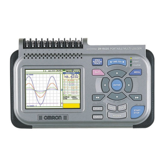
Page 14: Part Names
BEFORE USE Part Names Connection Procedures Setting the Date and Time Descriptions of the Control Panel Keys Descriptions of the Menu Screens... - Page 15 Battery cover Analog input terminals Alarm output terminal Power output connector for the humidity sensor External trigger terminal AC adapter connector Logic input terminal USB interface terminal Pulse input terminal GND terminal USB device terminal Part Names ZR-RX20 Start Up Guide...
-
Page 16: Connection Procedures
Use a flatblade screwdriver to push in the button above the ground terminal while connecting the grounding cable to the ZR-RX20. Connect the other end of the cable to ground. Important Connect the GND terminal for safe measurement. The ZR-RX20 must also be grounded when sharing a common ground level with other devices. Note The grounding cable is not provided as a standard accessory and must be prepared separately. -
Page 17: Making Connections To The Input Terminals
Connect each terminal in accordance with the name inscribed above each terminal. Attaching USB Memory You're able to store measured data directly to the USB memory device. Attach the USB memory to the USB device terminal. USB memory device Connection Procedures ZR-RX20 Start Up Guide... -
Page 18: Setting The Date And Time
Setting the Date and Time The ZR-RX20 includes a rechargeable internal battery for backup. If you are using the ZR-RX20 for the first time, charge the internal rechargeable battery and then make the date and time settings. Note If the ZR-RX20 is not used for a period of approximately three months, the internal rechargeable battery may be dis- charged and the date and time may revert to the initial settings. -
Page 19: Descriptions Of The Control Panel Keys
TRACE Used to make trace settings (set the waveform display to On or Off). Note: If the QUIT key is pressed when the ZR-RX20 is in the SPAN, POSITION, or TRACE mode, the display returns to MONITOR mode. TIME/DIV key Press the TIME/DIV key to change the time axis display range on the waveform screen. - Page 20 ZR-RX20 is turned on, the ZR-RX20 goes into USB Drive Mode. REVIEW key Press the REVIEW key to replay captured data. If the ZR-RX20 is in the Free Running status, data files that have already been captured are replayed. If the ZR-RX20 is still capturing data, the data is replayed in a 2-screen format.
- Page 21 [TRIG] menu. FILE key Press the FILE key to save data to the ZR-RX20's internal memory and to a USB memory device. NAVI key Press the NAVI key to display operational descriptions during the Free Running status, and during data capture and data replay operations.
-
Page 22: Descriptions Of The Menu Screens
Displays the status of the logic signal. (Blue = Hi, white = Lo) USB device lamp Turns green when a USB memory device has been inserted. When the ZR-RX20's internal memory or USB memory device is being accessed, this lamp turns red. - Page 23 During a data capture operation, this bar displays the remaining memory capacity of the device used for data capture. When data is being replayed, the display position information is displayed here. Descriptions of the Menu Screens ZR-RX20 Start Up Guide...
-
Page 24: Basic Operations
BASIC OPERATIONS Measurement Procedure 1. Preparations: Preparations for Data Capture 2. Setup: Setting the Temperature Measurement 3. Data Capture: Measuring the Temperature 4. Data Replay: Replaying Captured Data Convenient Functions... - Page 25 We want to check captured data even during a data capture operation. Items that must be T thermocouples, USB memory device supplied Note: If you do not have a USB memory device, capture data to the ZR-RX20's internal memory instead. Measurement Procedure ZR-RX20 Start Up Guide...
-
Page 26: Preparations: Preparations For Data Capture
Connect the thermocouple to measurement object 2 and the CH 2 terminal. Connect the AC adapter. Insert the USB memory device. Turn on the power supply. CH 1 T thermocouple CH 2 T thermocouple Measurement Measurement object 1 object 2 ZR-RX20 Start Up Guide 1. Preparations: Preparations for Data Capture... -
Page 27: Setup: Setting The Temperature Measurement
Select [TC-T] for the Range parameter for CH 1 and CH 2. (a) Move the cursor to the [Range] parameter opposite CH 1 and select [TC-T]. (b) Make the same setting for CH2. 2. Setup: Setting the Temperature Measurement ZR-RX20 Start Up Guide... - Page 28 (b) With the cursor on the [<MEM>] item in the following screen, press the ENTER key. (c) The file settings box shown in the following screen opens. This box is used to specify file names for the ZR-RX20's internal memory and for the USB 7 – – (c) –(c)(d)(e) (c)(d)(e) (d)(e) memory device.
- Page 29 · Use the QUIT key to cancel your setting Check that "<TEST>" appears opposite "Folder", move the cursor to the [OK] button, and then press the ENTER key. 7 – – (i) –(i) 2. Setup: Setting the Temperature Measurement ZR-RX20 Start Up Guide...
- Page 30 In the screen displayed below, we can check the capture destination, the amount of data that can be captured, and the allowable data capture time. This completes all the settings required for data capture. ZR-RX20 Start Up Guide 2. Setup: Setting the Temperature Measurement...
-
Page 31: Data Capture: Measuring The Temperature
Replaying data being captured Data that was captured in the past can be replayed while new data is being captured to the ZR-RX20. In addition, the past data can be compared with the current input waveform in a 2-screen format. - Page 32 -(a) -(a) (b) A confirmation message is displayed. Press the ENTER key. (c) Data capture ends, and the ZR-RX20 goes into the Free Running status. This completes the data capture operation. ZR-RX20 Start Up Guide 3. Data Capture: Measuring the Temperature...
-
Page 33: Data Replay: Replaying Captured Data
–(e) End data Replay ? [ENTER] Yes [QUIT] No Data replay ends, and the ZR-RX20 goes into the Free Running status. This completes our simple explanation of how to use the basic ZR-RX20 functions. 4. Data Replay: Replaying Captured Data... -
Page 34: Convenient Functions
Note The span, position and trace operations can be performed while the ZR-RX20 is in the Free Running status, while it capturing data, and while it is replaying data. The changes made are applied to the displayed data only, and so the original data is not affected in any way. -
Page 35: Specifications
SPECIFICATIONS Standard Specifications External Dimensions... -
Page 36: Standard Specifications
Gain: 0.01 % of F.S./° C Withstand voltage 350 Vp-p (between each input channel/main unit chassis; between each chs) 1 minute Insulation resistance Between main unit chassis: At least 50 MΩ (at 500 VDC) Standard Specifications ZR-RX20 Start Up Guide... - Page 37 Refer to the ZR-XRH1 (Option) specifications for humidity measurement accuracy. Be sure to use only the AC cable and the AC adapter provided as standard accessories. ZR-XRB1 is an option Excluding the AC adapter and battery ZR-RX20 Start Up Guide Standard Specifications...
-
Page 38: External Dimensions
External Dimensions (Unit: mm) External Dimensions ZR-RX20 Start Up Guide... -
Page 39: Revision History
A manual revision code appears as a suffix to the catalog number at the bottom of the front and back covers of this manual. Cat. No. Z256-E1-03 Revision code Revision code Date Revised contents April 2007 Original production August 2007 Minor corrections October 2007 Notice on EMC Directive added and minor corrections. Revision History ZR-RX20 Start Up Guide... - Page 40 Tel: (49)7032-811-0/Fax: (49)7032-811-199 OMRON ELECTRONICS LLC One Commerce Drive Schaumburg IL 60173-5302 U.S.A. Tel: (1) 847-843-7900/Fax: (1) 847-843-7787 OMRON ASIA PACIFIC PTE. LTD. No. 438A Alexandra Road # 05-05/08 (Lobby 2), Alexandra Technopark, Singapore 119967 Tel: (65) 6835-3011/Fax: (65) 6835-2711 OMRON (CHINA) CO., LTD.
Need help?
Do you have a question about the ZR-RX20 and is the answer not in the manual?
Questions and answers