Table of Contents
Advertisement
Quick Links
Advertisement
Table of Contents

Related Manuals for Omron ZR-RX70


Summary of Contents for Omron ZR-RX70
- Page 1 Portable Multi Logger ZR-RX70 User’s Manual Cat. No. Z283-E1-02...
- Page 2 ZR-RX70. When using the ZR-RX70, be sure to observe the following: · The ZR-RX70 must be operated by personnel knowledgeable in electrical engineering. · To ensure correct use, please read this manual thoroughly to deepen your understanding of the product.
- Page 3 APPLICATION CONSIDERATIONS (Please Read) GENERAL DESCRIPTION User’s Manual CHECKS AND PREPARATION SETTINGS AND MEASUREMENT SPECIFICATIONS APPENDIX Portable Multi Logger ZR-RX70...
- Page 4 LOSS OF PROFITS OR COMMERCIAL LOSS IN ANY WAY CONNECTED WITH THE PRODUCTS, WHETHER SUCH CLAIM IS BASED ON CONTRACT, WARRANTY, NEGLIGENCE, OR STRICT LIABILITY. In no event shall responsibility of OMRON for any act exceed the individual price of the product on which liability is asserted.
- Page 5 Performance data given in this document is provided as a guide for the user in determining suitability and does not constitute a warranty. It may represent the result of OMRON’s test conditions, and the users must correlate it to actual application requirements. Actual performance is subject to the OMRON Warranty and Limitations of Liability.
- Page 6 Indicates the possibility of electric shock under specific conditions. Indicates prohibition when there is a risk of minor injury from electrical shock or other source if the product is disassembled. Indicates general prohibitions for which there is no specific symbol. ZR-RX70 User’s Manual...
- Page 7 Be sure to connect the terminal of this product to the cable first, and connect the measurement object. Injuries from electric shock may occur in rare occasions as the result of disassembly. Never disassemble, deform under pressure or incinerate the main unit. ZR-RX70 User’s Manual...
- Page 8 • The ZR-RX70 conforms to the IEC60664-1 installation category II, and must not be used under the environment of the installation category III and IV. 3.Measurement category • The ZR-RX70 is classified as measurement category I defined by IEC61010-1, and must not be used within measurement category II, III and IV. 4.Power supply and wiring •...
- Page 9 • Do not drop or apply strong impact or force to the product. It may cause malfunction of the monitor or the main unit. 6.Maintenance • Do not use thinner, benzine, acetone or kerosene to clean this product. • Calibration should be performed periodically to maintain measurement accuracy. ZR-RX70 User’s Manual...
- Page 10 • Specal PC software “Wave Inspire RX“ (tryout) • Basic PC software “Smart Viewer RX70” • User's Manual PDF files (this manual) • “Wave Inspire RX“ Software Manual PDF files • “Smart Viewer RX70” Software Manual PDF files ZR-RX70 User’s Manual...
- Page 11 Editor’s Note Meaning of Symbols Menu items that are displayed on the ZR-RX70’s LCD screen, and windows, dialog boxes and other GUI elements displayed on the PC are indicated enclosed by double quotes “ ”. Visual Aids Indicates points that are important to achieve the full product performance, such as operational Important precautions.
- Page 12 MEMO ZR-RX70 User’s Manual...
-
Page 13: Table Of Contents
Changing the Display Language ....... . 38 ZR-RX70 User’s Manual... - Page 14 WEB Server Function ........100 ZR-RX70 User’s Manual...
- Page 15 Revision History ..........124 ZR-RX70 User’s Manual...
- Page 16 MEMO ZR-RX70 User’s Manual...
-
Page 17: General Description
GENERAL DESCRIPTION This chapter provides a general description of the ZR-RX70 and its features. Overview Features Operating Environment... -
Page 18: Overview
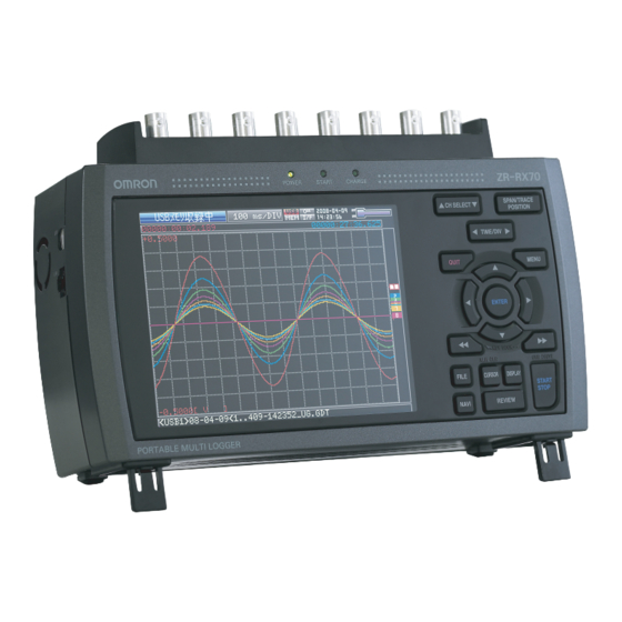
The ZR-RX70 (with color monitor and internal memory) are compact, lightweight, 8 channel data loggers. ZR-RX70 are also equipped with an internal flash memory to store data and enable the direct capture of a large volume of data to USB memory. -
Page 19: Features
• The USB drive mode function enables the ZR-RX70’s internal flash memory to be recognized as an external drive by your PC. (Connect the ZR-RX70 to your PC and turn on the power supply to the ZR-RX70 while holding down the [START] key.) -
Page 20: Operating Environment
Use both the stands of the ZR-RX70 when you use it at an angle. Otherwise, the unit will fall down. Open both the stands before use as shown in this figure. -
Page 21: Checks And Preparation
CHECKS AND PREPARATION This chapter explains how to check the ZR-RX70’s external casing and accessories, and how to prepare the ZR-RX70 for operation. Part Names and Functions Connecting the Power Cable and Turning on the Power 21 Connecting the Analog Input Terminal... -
Page 22: Part Names And Functions
Part Names and Functions This section describes the names and function of parts of the ZR-RX70. PC interface terminals Monitor Operation status LED Power switch • USB • POWER : ON when the power is ON • LAN • START : ON during data capture •... -
Page 23: Connecting The Power Cable And Turning On The Power
Important Be sure to use the AC cable and the AC adapter that are supplied as standard accessories.Connect the GND terminal for safe measurement. The ZR-RX70 must also be grounded when sharing a common ground level with other devices. Plug the AC cable into the AC adapter. - Page 24 Using the flat-blade screwdriver, press against the minus (–) button above the GND terminal, while connecting the grounding cable to the ZR-RX70. Connect the other end of the cable to ground. Note The ground cable is not provided as a standard accessory and must be prepared separately.
-
Page 25: Connecting To A Dc Power Supply
• Be sure to use the separately sold DC cable (ZR-XRD1). • Do not apply voltages exceeding the rated voltage (8.5 to 24 VDC). • Connect the GND terminal for safe measurement. The ZR-RX70 must also be grounded when sharing a common ground level with other devices. -
Page 26: Connecting The Analog Input Terminal
BNC connector The screw type terminal and the BNC connector are internally connected. Data entered to either of them can be measured. Note If you use plobe, use one with attenuation rate 1/1. Connecting the Analog Input Terminal ZR-RX70 User’s Manual... -
Page 27: Connection Diagram
Connection Diagram Important Make sure that the ZR-RX70 is not pulled by signal input cables when you connect them. The ZR-RX70 may fall down if it is pulled. Direct voltage input Thermocouple input Direct current input Direct voltage Compensation Direct current... -
Page 28: Logic Alarm Cable Connection And Functions
Input voltage range 0 to +24V max. (single-ended ground input) Threshold level Approx. +2.5V Hysteresis Approx. 0.5 V (+2.5 to +3 V) Note Switch between logic and pulse input. Internal Equivalence Circuit Logic Alarm Cable Connection and Functions ZR-RX70 User’s Manual... - Page 29 Number of input channels Output format Open collector output +5 V, 10 KΩ pull-up resistance Contact capacity 5 V to 24 V, 100 mA or below Internal Equivalence Circuit and Example of Wiring Connection Logic Alarm Cable Connection and Functions ZR-RX70 User’s Manual...
- Page 30 White with black dotted line Alarm output Yellow with red dotted line Yellow with black dotted line Pink with red dotted line : External trigger/ sampling input Pink with black dotted line Shielded Logic Alarm Cable Connection and Functions ZR-RX70 User’s Manual...
-
Page 31: Attaching Usb Memory
Attaching USB Memory Attaching USB memory to the ZR-RX70 allows you store measured data directly. Important <Specifications of supported USB memory> • Power source : +5 V • Power consumption : 250 mA or below • Capacity : No limit (except each file must be within 2 GB) You cannot use USB memory with a security function such as fingerprint authentication or with no shell (metallic part) in the connector area. -
Page 32: Connecting To A Pc
If the USB cable is used, the USB driver must be installed in your PC. Refer to “Installing the USB Driver” in the “PC Software Manual”. • Use an A-B type USB cable to connect the ZR-RX70 to a PC A connector... -
Page 33: Lan Connection
LAN Connection Use a LAN cable to connect the ZR-RX70 to a PC. LAN cable Cable Types • Use a crossing cable when connecting directly to a PC, without using a hub. LAN cable (crossing) • Use a straight cable when using a hub. -
Page 34: Using The Battery Pack (Zr-Xrb1: Option)
Note When you have the ZR-RX70 run on batteries, be sure to mount two battery packs with the same charge level. Do not use the battery packs with the different charge level at the same time. If you are not sure about the amount, charge each battery and then attach full-charged two battery packs. -
Page 35: Charging The Battery
When charging is attempted while the power is ON, charging may not be performed immediately depending on the temperature environment. In such a case, set the Screen Saver settings to ON. ZR-RX70 will start charging as soon as it is cooled down. Charging temperature: 15 to 35 °C •... -
Page 36: Connecting The Humidity Sensor (Option)
Connecting the Humidity Sensor (Option) Connect the + and – lead wires of the humidity sensor (the ZR-XRH1 option) to the desired terminals, and then insert the round connector into the 5V OUT connector on the ZR-RX70. Important Do not use the sensor in a strong electrolyte environment. Measured results may not satisfy to the stated. -
Page 37: Precautions To Observe When Performing Measurement
• Be sure to use only the AC adapter provided as a standard accessory. The rated power supply range for the adapter is 100 to 240 VAC, and the rated frequency is 50/60 Hz. Do not use any other voltages. For details, see “Connection Diagram” p. 25. Precautions to Observe When Performing Measurement ZR-RX70 User’s Manual... -
Page 38: Noise Countermeasures
Connect the signal chassis GND and the ZR-RX70’s chassis GND. Use a short, thick lead to connect the chassis GND of the measurement object to the ZR-RX70’s chassis GND. It will become even more effective if the ground potentials are the same. -
Page 39: Setting The Date And Time
Setting the Date and Time If you are using the ZR-RX70 for the first time, charge the internal rechargeable battery and then make the date and time settings. Important If the ZR-RX70 is not used for a period of approximately six months, the internal rechargeable battery may be dis- charged and the date and time may revert to the initial settings. -
Page 40: Changing The Display Language
Changing the Display Language You can choose the language displayed on the screen. The default display language is set to English when the ZR-RX70 is shipped overseas. ZR-RX70A: Japanese ZR-RX70A-E,-U,-B,-CHRO: English To change the display language, see the instructions in "OTHR:Language". -
Page 41: Settings And Measurement
SETTINGS AND MEASUREMENT This chapter describes the setting and measurement procedures for the ZR-RX70. Window names and functions Key Operation Operation Modes Setting Menus X-Y Measurement Example WEB Server Function... -
Page 42: Window Names And Functions
: Waiting for the time set on the timer : Capturing data and replaying captured data : Capturing data to the internal RAM of the ZR-RX70 : Capturing data to the internal flash memory of the ZR-RX70 : Capturing data to USB memory : Auto-saving data (Data captured in the internal RAM is being saved to the internal flash memory or USB memory.) - Page 43 For details on memory to be used for data capture, see p.94. 6. Remote display : The ZR-RX70 is in local mode. The ZR-RX70 can be operated from itself. : The ZR-RX70 is in remote mode. The ZR-RX70 can be operated from a PC except for some operations.
- Page 44 Size of data that has been captured ..Indicates how much of the above memory is currently in use for data capture. Remaining memory capacity available ..Indicates how much of the above memory remains available for data capture. Window names and functions ZR-RX70 User’s Manual...
- Page 45 Indicates the displayed position, cursor position, and trigger position. Cursor A position Trigger point location Cursor B position Total size of captured data Current waveform display position • Waiting for timer Indicates the time at which the timer expires. Window names and functions ZR-RX70 User’s Manual...
-
Page 46: Key Operation
Press this switch to select the channel to change the settings in the Waveform + Digital or X-Y screen. Press this switch to move the active display box in the Digital + Calculation Display screen. p.47 Key Operation ZR-RX70 User’s Manual... -
Page 47: Span/Trace/Position
/6 temperature levels the range * At OFF, data is captured all the same. * When ALL is set, setting values for CH1 is reflected on other channels. When CH1 is OFF, ALL cannot be set. Key Operation ZR-RX70 User’s Manual... -
Page 48: Time/Div
This key is used to change the colors of the waveforms in the X-Y screen. p.95 (4) MENU Open the settings window to capture data. For details on settings, see “Setting Menus”. p.57 Key Operation ZR-RX70 User’s Manual... -
Page 49: Quit
• To change the number of channels displayed in the Digital + Calculation Display screen keys). • To change the channel displayed in the box on the Digital + Calculation Display screen keys). 2-channel Display 4-channel Display 8-channel Display Full Channels + Statistical Calculation Display Key Operation ZR-RX70 User’s Manual... -
Page 50: Enter
• Stops capture during capture. • Press this key while turning the power ON to access USB Drive Mode. In USB Drive Mode, the internal memory is recognized by the PC as external storage media. Key Operation ZR-RX70 User’s Manual... -
Page 51: Review
The external storage media is recognized by the PC and data exchange becomes possible. Note In USB Drive Mode, the display on the ZR-RX70 is as shown below. Keep pressing [START/STOP] key until the display becomes as shown below. Important •... -
Page 52: Display
Pressing this key switches the window display as follows: <Waveform + Digital Screen> Displays waveforms and digital values. This is the default screen when the ZR-RX70 is powered on. The screen settings can be changed by using the [SPAN/TRACE/POSITION] key. -
Page 53: Cursor (Alarm Clear)
Cursor A <When alarm generated> When the alarm setting is “Hold generated Alarm”, the maintained alarm is cleared. Alarm-generated channels Alarm output terminal status • Black : Alarm is cleared • Red : Alarm is issued Key Operation ZR-RX70 User’s Manual... -
Page 54: File
This key is used to display the key operation content during Free Running, capture, or replay. During display of the NAVI screen, an explanation of how the key is used is displayed in the window. To exit the NAVI screen, press the NAVI key again. Key Operation ZR-RX70 User’s Manual... - Page 55 Press the [ENTER] key to confirm the value. The above operation is the basic procedure that may be used for each setting. However, precise procedure may vary between setting items. Please follow the procedure indicated by each menu. Key Operation ZR-RX70 User’s Manual...
-
Page 56: Operation Modes
The [FILE] key is used to perform file-related operations. Replay of last data (captured last time) The [REVIEW] key is used to replay captured data. Data replay The [FILE] key is used to select data that you want to replay and replay it. Operation Modes ZR-RX70 User’s Manual... -
Page 57: Capturing
) to move the cursor to captured data to check digital values. Operations available during Capturing and Replaying Moving cursor The [CURSOR] key is used to switch between cursors A and B. keys are used to move the cursors. Operation Modes ZR-RX70 User’s Manual... -
Page 58: Replaying
The [CURSOR] key is used to switch between cursors A and B. keys are used to move the cursors. File operations The [FILE] key is used to save data in the internal RAM to the internal flash mem- ory and USB memory. Operation Modes ZR-RX70 User’s Manual... -
Page 59: Setting Menus
Lower limit value Numeric value input Annotation setting Text input (31 characters max.) Waveform color setting Red/Green/Blue (RGB) 0 to 31 available for each color Perform Auto Zero ADJ. Execute Reset Auto Zero ADJ. Execute Setting Menus ZR-RX70 User’s Manual... - Page 60 Disables the measurement of input signals and the waveform and digital display. Voltage Used for measuring direct-current voltages. Temperature Used for measuring temperatures. Humidity Used for measuring humidity with humidity sensor ZR-XRH1. This selection sets the voltage range to 1V and disables EU settings. Setting Menus ZR-RX70 User’s Manual...
- Page 61 –270 to +2000°C 50°C 0 to +1760°C –270 to +2000°C 50°C 0 to +1300°C –270 to +2000°C 50°C 0 to +2000°C <Humidity Range> Range Maximum SPAN Minimum SPAN (p-p) Minimum Resolution 0 to +110% 1.0% 0.1% Setting Menus ZR-RX70 User’s Manual...
- Page 62 (7) User-Defined Unit Selects the converted unit, which can be specified as a user-defined character string consisting of alphanumerics. For details on text input, see p.88. The settings made in “Select” and “Unit” are reflected here. Setting Menus ZR-RX70 User’s Manual...
- Page 63 Specifies the digital input settings. (1)-6 Logic/Pulse Selects the digital input processing method. Setting Description Disables the measurement of digital input. Logic Digital input is processed as logic signals. Pulse Digital input is processed as pulse signals. Setting Menus ZR-RX70 User’s Manual...
- Page 64 (6) User-Defined Unit Selects the converted unit, which can be specified as a user-defined character string consisting of alphanumerics. For details on text input, see p.88. The settings made in “Select” and “Unit” are reflected here. Setting Menus ZR-RX70 User’s Manual...
-
Page 65: Data Settings
Selection Folder (File) Destination : MEM, USB1 Folder : Text input (if it is automatically named) File : Text input (if it is user-defined) Name Type Auto or User File Format Binary (GBD), Text (CSV) Setting Menus ZR-RX70 User’s Manual... - Page 66 (CSV), sampling intervals from 1 to 5ms cannot be selected. • When External is selected in the sampling interval, you cannot select External Input in the trigger setting. When the External Input is already set, the trigger is changed to Off. Setting Menus ZR-RX70 User’s Manual...
- Page 67 Specifies the number of data points to be captured to the internal RAM. This item can be set only when Internal RAM is selected in (2)-2. Before setting this item, check the time available for data capture ((A) in the figure). Setting Menus ZR-RX70 User’s Manual...
- Page 68 When the Repeated capturing is On, the text of “rep” showing repeat and a number showing the number of times of repeating are added as shown by 20050101-123456_UG_rep001.GBD. User : Captures data to a file with a user-defined name. Setting Menus ZR-RX70 User’s Manual...
- Page 69 Description (4) File Format Sets the file format in which you want to save data. : Creates a data file in Omron proprietary binary format. * Prevents tampering of data. : Creates a data file in a text format. * Cannot be replayed on the ZR-RX70.
- Page 70 (2)-6 Statistical Calculation Settings The ZR-RX70 can perform two statistical calculations. This section describes specifying the statistical calculation settings. Selection Description Calculation is not performed. Average Displays the simple average value of data being captured. Displays the maximum value of data being captured.
-
Page 71: Trig Settings
Analog : Off, ↑ H, ↓ L, Win In, Win Mode settings : Off, ↑ H, ↓ L Logic Pulse : Off, ↑ H, ↓ L Level Numeric value setting Output 1, 2, 3, 4 Setting Menus ZR-RX70 User’s Manual... - Page 72 ⇒ When Time is selected, set the time to start capturing data. The actual timing conditions for data capture are related to the timer. See also Sections “(3)-1 Timer Mode” p. 70, “(3)-3 Stop Side Source Settings” p. 71, and “(3)-7 Timer Trigger Information” p. 72. Setting Menus ZR-RX70 User’s Manual...
- Page 73 • the start side source setting is Off or Time, and • the stop side source setting is set to Time, or the stop side source setting is set to Off and the data capture destination is set to Internal RAM. Setting Menus ZR-RX70 User’s Manual...
- Page 74 Example) Suppose CH1 and CH2 are set to Output 1 and CH3 and CH4 to Output 2. If either CH1 or CH2 meets the conditions, Alarm Output 1 occurs. If either CH3 or CH4 meets the conditions, Alarm Output 2 occurs. <Trigger Level Settings> <Alarm Settings> Setting Menus ZR-RX70 User’s Manual...
- Page 75 There is an error of ±1% at the maximum to the range between the trigger setting level and the level at which the trigger is actually generated (trigger generation level), e.g. ±0.01V in the 1V range. Approx. 1.3% of trigger hysteresis is provided to the trigger generation level. Approx. 0.5% of alarm hysteresis is provided. Setting Menus ZR-RX70 User’s Manual...
- Page 76 The alarm is cleared once at the start of data capture, and then compared at 5-ms intervals. When an alarm is generated upon start, the first few data*1 becomes “L” (status in which no alarm is generated). *1: The number of data showing “L” may vary depending on the sampling interval. Setting Menus ZR-RX70 User’s Manual...
-
Page 77: Opt Settings
Sets the USB ID number of the ZR-RX70. Specify a number from 0 to 9. When you control more than one unit of the ZR-RX70 with one PC, assign a unique USB ID to each of them. Important You must restart MT100 after any change is made to a setting value. - Page 78 (4)-3 TCP-IP Settings Specifies TCP-IP settings used to connect the ZR-RX70 to an Ethernet. Important You must restart MT100 after any change is made to a setting value. Changes are applied upon restart. Setting items Description IP Address Sets the IP address of MT100 (0 to 255. 0 to 255. 0 to 255. 0 to 255).
-
Page 79: Othr Settings
Sets the brightness of the LCD backlight. (5)-2 Screen Saver Automatically turns off the display if the ZR-RX70 is not operated within a specified interval. Turning off the display frequently using the screen Saver function allows longer lifetime of the LCD screen. - Page 80 (5)-8 Date/Time Sets the clock of the ZR-RX70. Sets the built-in clock (Date/Time) of the ZR-RX70. If Network Time is set, the clock of the ZR-RX70 is automatically adjusted via the network. For details, see “Network Time Settings” p. 79.
- Page 81 Games are available. The score is stored for each user. (5)-13 Information Displays system information for the ZR-RX70. Network Time Settings The ZR-RX70 synchronizes the time of the built-in clock with that of a time server via an Ethernet. Setting Description Network Time Enables or disables this feature.
-
Page 82: File Menu
<Free Running> <Replaying> <Capturing/Capturingand Replaying> <Auto Saving> <X-Y Display Screen> (6)-1 File Replay and Operation Replay data or operate files in the internal flash memory or USB memory. File replay is explained in detail on p.85. Setting Menus ZR-RX70 User’s Manual... - Page 83 Description (1) File Format Sets the file format in which you want to save data. : Creates a data file in Omron proprietary binary format. * Prevents tampering of data. : Creates a data file in a text format. * Cannot be replayed on the ZR-RX70.
- Page 84 (6)-3 Bitmap Save The ZR-RX70 can save a screen copy of waveforms, etc. to a bitmap file. This menu is used to specify the save destination, file name, etc. of a bitmap file. <If the Name Type is Auto> <If the Name Type is User>...
- Page 85 CND.....Data format (Settings file format of the ZR-RX70) User : Captures data to a file with a user-defined name. (6)-6 Load Loads the settings of the ZR-RX70 from a file. Setting Description (1) Folder Specifies a folder to which you want to save data.
- Page 86 You can save the image replayed from the captured data in a bitmap file as the waveform image and use it as source image for comparison. Setting Menus ZR-RX70 User’s Manual...
-
Page 87: File Box
Format disk ........Formats the disk. * Details of allowed operation will depend on the operation target. Moves between folders. : Move up one folder. : Move down one folder. ENTER Finalizes the operation. QUIT Closes the file box. Setting Menus ZR-RX70 User’s Manual... - Page 88 In the [Data Save Destination], choose [Folder] and press the [ENTER] key. Use the key to move to the target folder. Use the key to select [Create new folder]. Press the [ENTER] key. In the [New folder name] box that appears, type in “TEST”. Setting Menus ZR-RX70 User’s Manual...
- Page 89 Use the key to choose [Select file/folder]. Use the key to move the cursor to the created “TEST” folder, and press the [ENTER] key. Select [OK] to close the screen. Setting Menus ZR-RX70 User’s Manual...
-
Page 90: Text Input
Text used for each operation When you bring the cursor to a character and press ENTER, operation the character is entered. After you finish entering characters, move the cursor to OK and then press ENTER. Setting Menus ZR-RX70 User’s Manual... -
Page 91: Data Replay Menu
Prev. Search Execute Statistical Calcula- Execute Execute tion between Cursors X-Y Display Settings X-ch CH1 to CH8 Y-ch CH1 to CH8 Trace Off, On Execute X-Y for All Data Execute Execute X-Y between Cursors Execute Setting Menus ZR-RX70 User’s Manual... - Page 92 Sets a function that moves the two cursors simultaneously when you move them. Selection Description The two cursors are not synchronized. Only the specified cursor moves. The two cursors move in synchronization. Cursor A is always the fulcrum. Setting Menus ZR-RX70 User’s Manual...
- Page 93 Section (9)-7 Level Settings). (9)-9 Prev. Search Moves the cursor to a position before the current cursor position where the search conditions are met (Set the search conditions in Section (9)-7 Level Settings). Setting Menus ZR-RX70 User’s Manual...
- Page 94 * D: data n: number of data (9)-11 X-Y Display Settings The ZR-RX70 can convert waveform data to X-Y display. This menu is used to assign channels and make other settings to convert the data to X-Y display. Setting Selections available X-ch Sets a channel to be assigned to the X-axis in each zone.
-
Page 95: Navi Menu
: Searches the future side. ZONE key can be used to change the zone division. Free Running SAMPLE key can be used to change the sampling interval. CLEAR Press the key to clear the waveforms on the screen. Setting Menus ZR-RX70 User’s Manual... -
Page 96: Canceling Key Lock With Password
(12) Canceling Key Lock with Password A password can be set to ZR-RX70 to cancel the key lock. (No password is set at factory default.) <Operation flow> Set the password. Press the , and [ENTER] keys at the same time to display the password setting screen shown below. -
Page 97: X-Y Measurement Example
You can set the colors of the waveforms (colors of X-Y channels) displayed on the X-Y Display screen, but not change those on the Y-T screen. Press the [SPAN/TRACE/POSITION] key three times to select the TRACE. X-Y Measurement Example ZR-RX70 User’s Manual... - Page 98 The CLEAR serves a similarly function to paper change for the X-Y recorder (dedicated machine). The paperless ZR-RX70 adopts a means of clearing the waveform on the screen instead of changing recording paper. Press the [QUIT] key to return to the previous display. Capturing is not yet started. Since the pen has been moved up, yellow dots are moving but the path doesn’t remain on the screen.
- Page 99 Press the [START/STOP] key to start capturing and move down the pen. The dotted path is dis- played. X-Y Measurement Example ZR-RX70 User’s Manual...
-
Page 100: Example 2
Note This is not the function of pass/fail judgment automatically performed by the ZR-RX70. Press the [DISPLAY] key three times to display the X-Y Display screen. Call up the past waveform image. Press the [FILE] key. - Page 101 Press the [START/STOP] key to start capturing. The current image of waveforms is overlaid on the past one. Note At this time, only the current data is in fact captured. X-Y Measurement Example ZR-RX70 User’s Manual...
-
Page 102: Web Server Function
• http ....Protocol to access the server. HTTP (Hyper Text Transfer Protocol) • IP address..Type in the IP address of the ZR-RX70 to monitor. • Index.html ..File name. This is fixed to Index.html. Note The port number can be omitted. Set 80 to the port number if necessary. - Page 103 Zoom........Enlarges only the LCD screen of ZR-RX70. Digital ........Displays the ZR-RX70 measured value digitally. Download of device file ..Allows data captured with ZR-RX70 to be downloaded to your PC via FTP. OMRON Web site ....Accesses to our Web site.
- Page 104 Remote key operation To operate ZR-RX70 from a remote location, click the corresponding ZR-RX70 panel keys on the screen. OMRON ZR-RX70 http://192.168.0.1/index.html KEY LOCK ......Sets and cancels key lock. PASSWORD ......Sets and cancels the password. WEB Server Function...
- Page 105 Press this key to switch among MONITOR, SPAN, POSITION, and TRACE......Cursor keys Screen update speed..... Specifies the speed in which the screen is updated. Available update speeds are 2, 5, and 10 seconds. WEB Server Function ZR-RX70 User’s Manual...
- Page 106 Screen update speed..... Specifies the speed in which the screen is updated. Available update speeds are 2, 5, and 10 seconds. Download of device file Allows memory data from ZR-RX70 and data in USB memory to be downloaded to your PC. WEB Server Function ZR-RX70 User’s Manual...
- Page 107 • Upload file • Delete file/folder • Create file/folder • Change file name/folder name To enable data to be written to the ZR-RX70, the login account name must be changed. Please use the following table as a guide. Account name Password...
- Page 108 MEMO WEB Server Function ZR-RX70 User’s Manual...
-
Page 109: Specifications
SPECIFICATIONS This chapter describes the basic specifications for the ZR-RX70. Standard Specifications Accessory/Option Specifications External Dimensions... -
Page 110: Standard Specifications
(Attenuation) –3 dB/6 dB oct Withstand between input 1000 Vp-p (1 minute) voltage channel - ter- minals between input 1000 Vp-p (1 minute) channel - ter- minal/GND Insulation between input At least 50 MΩ (at DC500 V) resistance terminal/GND Standard Specifications ZR-RX70 User’s Manual... - Page 111 At least 30 minutes after the power supply is turned on Folter Line GND connection + B54:B84 A logic alarm cable ZR-XRL1 (optional) is necessary. 23°C environment 2 battery packs should be mounted when using battery pack. Standard Specifications ZR-RX70 User’s Manual...
-
Page 112: Analog Input Measurement Accuracy
± (0.1% of rdg + 2.5°C) Operating environment 23°C ± 5°C • Left for at least 30 minutes after the power supply is turned on • Filter Line • GND connection φ φ • Thermocouple used is T:0.32 , other:0.65 Standard Specifications ZR-RX70 User’s Manual... -
Page 113: Main Functions
Ethernet (10BASE-T/100BASE-TX) Interface USB (USB 2.0 HIGH-SPEED) Ethernet functions Web server function: Displays ZR-RX70 screen image on Web browser and operates ZR-RX70 from the Web brouser. FTP server function: Transfers and deletes files from internal memory and USB memory. NTP client function: Corrects the time of internal clock. - Page 114 Neither the internal flush memory nor USB memory can be selected if a unit in µs is selected. This function is available only if data is captured to the internal RAM. Realtime and between cursors specified (during data replay) Standard Specifications ZR-RX70 User’s Manual...
-
Page 115: Accessory/Option Specifications
Don't start up the other application software, as WaveInspire works. And don't work other several operation. (For example, screen saver, virus scan program, copying or moving files, searching file etc.) Accessory/Option Specifications ZR-RX70 User’s Manual... -
Page 116: Battery Pack
When the battery is running low, measured data is saved and the file is closed automatically. * When two battery packs are mounted on ZR-RX70. (One sufficient for battery charging) When capturing to internal memory at a sampling speed of 1 sec, using new battery packs at +25°C environment. -
Page 117: External Dimensions
External Dimensions ZR-RX70 mounting screw holes (Unit: mm) 23.5 Two, M4, depth6 24.6 External Dimensions ZR-RX70 User’s Manual... - Page 118 MEMO External Dimensions ZR-RX70 User’s Manual...
-
Page 119: Appendix
APPENDIX Error Messages and Countermeasures Index Revision History... -
Page 120: Error Messages And Countermeasures
Unable to establish a connection. In connected test in the network time Please check the network setting setting,when not connected with the and the synchronous server setting network server,it is displayed. of ZR-RX. Error Messages and Countermeasures ZR-RX70 User’s Manual... -
Page 121: List Of File Error Messages
"Disk is full" is usually displayed. cause. Please increase the capacity of the • Disk is full. disk as it erases an unnecessary • Neither the file nor the directory file. are created any further. Error Messages and Countermeasures ZR-RX70 User’s Manual... - Page 122 MEMO Error Messages and Countermeasures ZR-RX70 User’s Manual...
-
Page 123: Index
Level Operations DC Power Supply, Connecting Logic Default Settings Demo Waveform Mode Department name Main Functions Direction key MENU key Display Misc. Language Mode 54, 73 DISPLAY key Monitor Edge Operations ENTER key EU (Scaling) 60, 62 Index ZR-RX70 User’s Manual... - Page 124 Change Conds Load setting Save setting Signal Types SPAN Span setting 45, 61 SPAN/TRACE/POSITION key Standad Specifications 108, 118, 119 Start Side Source Settings Start/Stop Confirmation Message 78 START/STOP key Statistical Calculation Settings Stop Side Source Setting Index ZR-RX70 User’s Manual...
- Page 125 MEMO Index ZR-RX70 User’s Manual...
-
Page 126: Revision History
A manual revision code appears as a suffix to the catalog number at the bottom of the front and back covers of this manual. Cat. No. Z283-E1-02 Revision code Revision code Date Revised contents February 2009 Original production October 2009 Function addition according to software upgrade (Ver 2.03) Revision History ZR-RX70 User’s Manual... - Page 127 Regional Headquarters OMRON EUROPE B.V. OMRON (CHINA) CO., LTD. Sensor Business Unit Room 2211, Bank of China Tower, © OMRON Corporation 2009 All Rights Reserved. Carl-Benz-Str. 4, D-71154 Nufringen, 200 Yin Cheng Zhong Road, Germany In the interest of product improvement,...
Need help?
Do you have a question about the ZR-RX70 and is the answer not in the manual?
Questions and answers