
Related Manuals for tousek TPS 20


Summary of Contents for tousek TPS 20
- Page 1 Mounting and installation manual Master / Slave combination TPS 20 for opposite sliding gates TPS 20 Safety Sensor...
-
Page 2: Table Of Contents
Declaration of incorporation ........................... 31 This manual is the sole property of the TOUSEK Ges.m.b.H. and may not be made available to competitors. All rights reserved. No part of it may be reproduced without our prior written permission. We will not accept liability for any claims resulting from misprints or errors. This edition of the manual replaces all earlier publications of the same. -
Page 3: Important Warning And Safety Notes For Mountinga And Operating
EU and in the individual countries have to be strictly followed. • The TOUSEK Ges.m.b.H. cannot be held liable for any claims resulting from disregards of the laws and standards in force during the installation and operation. -
Page 4: Notes, General Characteristics, Function, Technical Data
General Sliding gate operator TPS 20 / Master-Slave Characteristics TPS 20 • Suitable for heavy duty use (80% duty cycle) • Large, illuminated LC-Display (2x16 characters) • Clear text menu programmable via four buttons • Operation mode is selectable (Impulse, Automatic, Deadman) •... -
Page 5: Mounting
ATTENTION ! • ATTENTION: Mechanical limits are necessary! • ATTENTION: The sliding gate operator TPS 20 has been developed and designed for the automation of hori- zontally travelling sliding gates. Gates on sloping tracks (i.e. gates which follow an inclined, non-horizontal, travel path) must be automated with additional safety devices (which make sure that the gate cannot start moving on its own from any gate position). - Page 6 • Only double-insulated cables, which are suitable for underground usage (e.g. E-YY-J) may be used. • In case that special regulations require another type of cable, cables according to these regulations have to be used. Mounting dimensions TPS 20 (in mm) Ground plate (1a) Cable inlet...
- Page 7 • Do not weld the individual gear rack elements together! • With a gate weight of >1000 kg we recommend using racks in a wider version. - 7 - tousek / EN_TPS-20-M-S_09 / 25. 03. 2020...
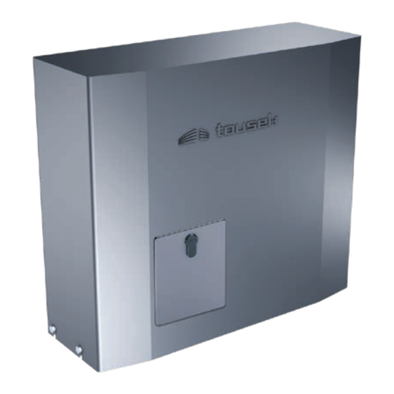
- Page 8 In case of a power failure or other defect the drive pinion can be disengaged from the gearmotor as follows: • Switch off power supply ! For emergency release of the TPS 20 the hous- ing flap, which can be locked with a profile half cylinder, must first be opened! You will find the emergency release key packed together with the installation manual.
-
Page 9: Control Unit Tps 20
Control board Sliding gate operator TPS 20 / Master-Slave Overview of the control unit Attention During connection, adjustment and maintenance works please take care, that the electronic circuit board won´t be damaged by moisture (rain). Display ENTER – Important The optional „tousek-connect“ or the „tousek service interface“... - Page 10 3.1 Terminal assignment Sliding gate operator TPS 20 / Master-Slave The stop input (t.30/31) has no emergency stop function! - In order to ensure the emergency stop function, provide the supply line with an all-pole disconnecting emergency stop switch, that locks after actuation!
- Page 11 • IMPORTANT: The control lines (sensor, buttons, radio, photocells, etc.) have to be laid separately from the 230V lines (supply line, motors, signal lamp). - 11 - tousek / EN_TPS-20-M-S_09 / 25. 03. 2020...
-
Page 12: Programming, Menu Structure
3.2 Adjustments - overview Sliding gate operator TPS 20 / Master-Slave Programming buttons Adjustments - overview • Before starting the programming, please choose the language. Use the buttons + or - to choose menu langua- ge and confirm with ENTER. - Page 13 The menu points courtyard lamp and control lamp will only appear on display if in menu „Additional module“ courtyard lamp/control lamp is selected. ENTER integrated control board for sliders TPS 20 / Master-Slave - 13 - tousek / EN_TPS-20-M-S_09 / 25. 03. 2020...
-
Page 14: 3.3 Connections And Adjustments
3.3 Connections and adjustments Sliding gate operator TPS 20 / Master-Slave Warning • Before removing the control cover, the • The product is not suitable for installation in explosion- main switch must be turned off! hazardous areas. • If the control is power supplied, its inner part is under •... - Page 15 The stop input has no emergency stop function! - In order to ensure the emergency stop function, provide the supply line with an all-pole disconnecting emergency stop switch, that locks after actuation! - 15 - tousek / EN_TPS-20-M-S_09 / 25. 03. 2020...
-
Page 16: Safety
during closing stop then close: an interruption of the photocell during closing makes the motor stop as long as the photocell stays interrupted. After release of the photocell, the gate closes. - 16 - tousek / EN_TPS-20-M-S_09 / 25. 03. 2020... - Page 17 1 2 3 4 5 Important • as the LS 45/2 has no SYNC-function, both photocell transmitters and receivers must be mounted on dif- ferent sides! receiver 2 transmitter 2 - 17 - tousek / EN_TPS-20-M-S_09 / 25. 03. 2020...
-
Page 18: Safety Edges
active Side edge 2 CLOSE CLOSE 50/55 not active active not active Side edge 3 OPEN OPEN 50/56 radio edge TX TX 400 - 18 - tousek / EN_TPS-20-M-S_09 / 25. 03. 2020... - Page 19 • Connection and detailed information of radio transmission system TX 310 see according manual.. Inductive system TX 400i • Connection and detailed information of inductive system TX 400i see according manual.. - 19 - tousek / EN_TPS-20-M-S_09 / 25. 03. 2020...
-
Page 20: Motor
Impulse mode: Impulse through impulse switch/button or CLOSE-button to start closing of gate. Automatic mode, pause time 1-255s adjustable [increment 5]: gate closes automatically after the adjusted pause time (Exception: see adjustment „Automatic mode“ / „only complete opening“). - 20 - tousek / EN_TPS-20-M-S_09 / 25. 03. 2020... - Page 21 24Vd.c., max. 2W Gate in OPEN-Position Gate in CLOSE-Position Gate opens or closes Gate stopped or fault (Gate not in end position) Gate in OPEN-position signal contact: 0 = open, 1= closed - 21 - tousek / EN_TPS-20-M-S_09 / 25. 03. 2020...
-
Page 22: Lamps / Lights
If the gate is closed, the pilot lamp expires Illuminates in open position: Pilot lamp is illuminated as soon as the gate has reached end position open. - 22 - tousek / EN_TPS-20-M-S_09 / 25. 03. 2020... -
Page 23: Diagnosis
DAYS HOURS : MINUTES : SECONDS $$$$$$$$$$$$$$$$ T -00 00:00:00.0 $$$$$$$$$$$$$$$$ Event Type of event Status Sensor Diagnosis Degree and signal strenght of rotation speed sensor is shown on display. - 23 - tousek / EN_TPS-20-M-S_09 / 25. 03. 2020... -
Page 24: Connection Radio Receiver
• The product may only be used in accordance with its original purpose, for which it has been exclusively designed, and which is described in these installation and operating instructions (especially children have to be instructed). The TOUSEK Ges.m.b.H. rejects any liability if the product is used in any way not fully conforming to its original purpose as stated herein. -
Page 25: Commissioning
Putting into operation Sliding gate operator TPS 20 / Master-Slave Important: preparation works • Connect the master control devices, safety equipment and motors according to the safety rules. Achtung: If no stop button is connected to the master or slave, the terminals 30/31 of the corresponding con- trol unit (master and / or slave) have to be bridged (factory-provided inserted bridge). - Page 26 TX 400 change ? YES close open $$$$$$$$$$$$$$$$ Side edge1 OPEN $$$$$$$$$$$$$$$$ Side edge1 OPEN $$$$$$$$$$$$$$$$ $$$$$$$$$$$$$$$$ active close open confirm $$$$$$$$$$$$$$$$ Side edge1 OPEN $$$$$$$$$$$$$$$$ not active - 26 - tousek / EN_TPS-20-M-S_09 / 25. 03. 2020...
- Page 27 After carrying out an emergency release or after a power failure, press and hold the impulse button until the gate is in open position and the display shows „gate open“. - 27 - tousek / EN_TPS-20-M-S_09 / 25. 03. 2020...
-
Page 28: Error Diagnosis
Troubleshooting guide Sliding gate operato TPS 20 / Master-Slave Error Possible reason Solution stop-button not connected or not connect or bridge stop-button > use Display:„Stop-button released“ bridged status display for help check correct connection hence Display „Photocell released“ photocell interrupted remove obstacle >... -
Page 29: Cable Plan
- 29 - tousek / EN_TPS-20-M-S_09 / 25. 03. 2020... -
Page 30: Dimensioned Drawings
Dimensional Drawing TPS 20 • Maße in mm Z15M4 Distance console (optional) We reserve the right to change dimensions and technical specifications without prior notice. - 30 - tousek / EN_TPS-20-M-S_09 / 25. 03. 2020... -
Page 31: Declaration Of Incorporation
Date/ Signature response to a duly substantiated request. TOUSEK Ges.m.b.H., A1230 Wien, Zetschegasse 1, Austria is authorized to compile the technical documentation. The incomplete machine cannot be put into service, until it... - Page 32 Buitenheide 2A/ 1 Tel. +32/ 11/ 91 61 60 your service partner: Fax +32/ 11/ 96 87 05 info@tousek.be Tousek Sp. z o.o. Poland PL 43-190 Mikołów (k/Katowic) Gliwicka 67 Tel. +48/ 32/ 738 53 65 Fax +48/ 32/ 738 53 66 info@tousek.pl...
Need help?
Do you have a question about the TPS 20 and is the answer not in the manual?
Questions and answers
we kunnen het hek wel open bellen maar niet meer automatisch dicht wat zou dat kunnen zijn
The Tousek TPS 20 gate may open manually but not close automatically due to the following possible reasons:
1. Automatic Mode Not Enabled – The gate may not be set to automatic mode. Ensure the automatic mode is activated and the pause time is correctly adjusted (1-255 seconds).
2. Safety Sensor Obstruction – Photocells or safety sensors may be blocked, misaligned, or faulty, preventing automatic closure. Check and clean the sensors.
3. Control Wiring Issue – The control lines (buttons, radio, photocells) must be correctly wired and separated from the 230V lines. Incorrect wiring may prevent automatic closing.
4. Power Supply Issue – Ensure the control board is properly powered and that there are no electrical faults.
5. Optional Module Settings – If an additional module (e.g., courtyard lamp or gate status display) is installed, ensure its settings do not interfere with operation.
6. Main Switch Off or Faulty – The main switch should be turned on and functioning properly.
Check these factors to diagnose and resolve the issue.
This answer is automatically generated