
Subscribe to Our Youtube Channel
Related Manuals for Landoll 334C


Summary of Contents for Landoll 334C
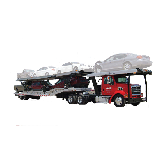
- Page 1 MODEL 334C CAR CARRIER OPERATOR’S MANUAL 1900 NORTH STREET MARYSVILLE, KANSAS 66508 (785) 562-5381 F-274-1299 12/99...
- Page 2 This warranty is void if any part not supplied by LANDOLL is used in assem- bly or repair, or if the machine has been altered, abused, or neglected. LAN-...
- Page 3 MODEL 334C CAR CARRIER OPERATOR’S MANUAL PURCHASED FROM: DATE ADDRESS: PHONE NO.: SERIAL NO.:...
- Page 4 424-9393 (or 366-0123 in Washington, D.C. area) or write to: NHTSA, U.S. Depart- ment of Transportation, Washington, D.C. 20590. You can also obtain other infor- mation about motor vehicle safety from the Hotline. In the event of a defect or problem with your LANDOLL equipment, please notify LANDOLL CORPORATION: LANDOLL CORPORATION...
-
Page 5: Table Of Contents
TABLE OF CONTENTS SECTION DESCRIPTION PAGE NO. INTRODUCTION STANDARD SPECIFICATIONS OPERATING INSTRUCTIONS GENERAL ......... . . 3-1 PRE-COUPLING OF SEMITRAILER AND TRACTOR . - Page 6 SAFETY PRECAUTIONS THIS IS THE SAFETY ALERT SYMBOL. IT IS TO ALERT YOU TO POTEN- TIAL PERSONAL INJURY HAZARDS. OBEY ALL SAFETY MESSAGES THAT FOLLOW THIS SYMBOL TO AVOID POSSIBLE INJURY OR DEATH. DANGER DANGER INDICATES A POTENTIALLY HAZARDOUS SITUATION WHICH, IF NOT AVOIDED, WILL RESULT IN DEATH OR SERIOUS IN- JURY.
-
Page 7: Introduction
INTRODUCTION This manual provides operating, servicing, and maintenance instructions for Model 334C car carrier, manufactured by Landoll Corporation, Marysville, Kansas 66508. SECTION 1 gives basic instructions on the use of this manual. SECTION 2 gives product specifications. These specifications supply lengths and measures for your equipment. -
Page 9: Standard Specifications
FRONT OVERHANG: ............24" TO 36" MODEL 334C - 4 CAR CARRIER OVERALL LENGTH. - Page 10 HYDRAULIC HOOKUP: QUICK COUPLERS............3/4" MAXIMUM OPERATING PRESSURE** .
-
Page 11: General
LANDOLL CORPORATION GENERAL TORQUE SPECIFICATIONS (REV. 4/97) THIS CHART PROVIDES TIGHTENING TORQUES FOR GENERAL PURPOSE APPLICATIONS WHEN SPECIAL TORQUES ARE NOT SPECIFIED ON PROCESS OR DRAWING. ASSEMBLY TORQUES APPLY TO PLATED NUTS AND CAPSCREWS ASSEMBLED WITHOUT SUPPLEMENTAL LUBRICATION (AS RECEIVED CONDITION). - Page 12 LANDOLL CORPORATION HYDRAULIC FITTING TORQUE SPECIFICATIONS JIC, ORS, & ORB (REV. 10/97) THIS CHART PROVIDES TIGHTENING TORQUES FOR HYDRAULIC FITTING APPLICATIONS WHEN SPECIAL TORQUES ARE NOT SPECIFIED ON PROCESS OR DRAWING. ASSEMBLY TORQUES APPLY TO PLATED CARBON STEEL AND STAINLESS STEEL FITTINGS ASSEMBLED WITHOUT SUPPLEMENTAL LUBRI-...
- Page 13 OPERATING INSTRUCTIONS 3-1 GENERAL This section supplies information for operation 3-1.3 Air Brake System of the semitrailer. It describes and locates controls The air brake system of the semitrailer is oper- and gives general operation procedures. Read all ated from the towing vehicle after coupling. The instructions, warnings, cautions, and danger notes towing vehicle’s air system must be coupled to the before attempting to operate the semitrailer.
-
Page 14: Pre-Coupling Of Semitrailer And Tractor
3-1.5 Electrical 3-1.6 Hydraulic The only electrical operation required of the The manual controls are located on the driver’s operator is interconnection of the towing vehicle side of the trailer. The controls can be operated by electrical cable plug with the semitrailer electrical a radio transmitter that is supplied standard. -
Page 15: Coupling Of The Tractor To The Semitrailer
3-3 COUPLING OF THE TRACTOR TO THE SEMITRAILER CAUTION DANGER PUSHING SEMITRAILER BACKWARDS KEEP ALL PERSONNEL CLEAR OF CAN DAMAGE LANDING GEAR. FRONT, REAR, AND SIDES OF TRAC- TOR AND SEMITRAILER DURING COU- 3-3.3 Slowly back the tractor so its fifth wheel PLING, COMPONENT OPERATIONS, contacts the front of the kingpin plate on the AND UNCOUPLING. -
Page 16: Tractor And Semitrailer Check-Out
TRACTOR AND SEMITRAILER CHECK-OUT WARNING 3-5.1 While hydraulic power is operating, raise the front end of the semitrailer with the TRAILER TILT CONTROL (See Figure 3-2) FAILURE TO PROPERLY SET AND until weight is off the landing gear. Raise C H E C K PA RKI NG BRA KE , AN D landing gear. -
Page 17: Towing The Semitrailer
3-6 TOWING THE SEMITRAILER CAUTION 3-6.1 Driving the tractor with the semitrailer coupled behind requires constant attention to the overall length. Turning, passing, acceler- IF A FAULT EXISTS IN THE SEMI- ating, braking, stopping, and back-up require TRAILER ABS, NORMAL BRAKING special considerations. -
Page 18: Parking The Semitrailer
3-7 PARKING THE SEMITRAILER 3-7.1 Position tractor/trailer rig on a level, solid surface. 3-7.3 Chock wheels. 3-7.2 Set the PARKING BRAKE, not the 3-7.4 Check for any air leaks in lines, relay semitrailer emergency hand brake, and valve, brake pods, or any other air system check for proper brake holding. -
Page 19: Hydraulic And Air Lock Controls
3-9 HYDRAULIC AND AIR LOCK CONTROLS 3-9.1 For manual control operation, switch the 3-9.4 The DECK TILT CONTROLS operate toggle on the right end of the control panel to the two sets of arms which support the upper “MANUAL”. For remote control operation, deck. -
Page 20: Winch Controls
3-9.6 The MANUAL LOCK CONTROLS (front UNLOCK Turn the lever clockwise as far as it and rear arm locks) are the levers on the air will go. In this position, the arm will un- valves next to the Hydraulic control valves. lock when the DECK TILT CONTROL There is one for each of the deck tilt arms. -
Page 21: Remote Control Operation
3-11 REMOTE CONTROL OPERATION 3-11.1 The POWER SWITCH is located on the 3-11.3 The DECK SELECTOR is in the middle top of the box and must be turned on for the of the front panel. (See Figure 3-4). the remote control to operate (See Figure LOWER When the deck selector is in this posi- 3-4). -
Page 22: Adjusting Adjustment Arms
3-12 ADJUSTING ADJUSTMENT ARMS There are two sets of adjustment arms con- 3-12.3 When the arm reaches the desired po- necting the upper deck to the lower deck. Each sition, release the LOCK CONTROL and arm must be unlocked as it is adjusted and locked joggle the TRAILER TILT CONTROL until when it is in position. -
Page 23: Preparation For Loading Procedure
Figure 3-6 Preparation for Loading 3-13 PREPARATION FOR LOADING PROCEDURE WARNING 3-13.1 Practice all standard industrial safety standards. Do not load any payload that will overload any component of the trailer or 1. THE SEMITRAILER MUST BE COU- cause an unsafe condition. PLED TO A TRACTOR AND THE LAND- 3-13.2 Park the tractor/trailer in a straight line... - Page 24 Figure 3-7 Lining Up the Over-the-Cab Deck Figure 3-8 Loading the Over-the-Cab Deck 3-12...
-
Page 25: Loading The 331 Over-The-Cab Deck
#2. Prepare the vehicle to be winched 3-14.3 Swing down the wheel stops on the onto the over-the-cab deck. front of the 334C upper deck. 3-14.4 Slide the over-the-cab deck back to 1/2" DANGER from the 334C upper deck. -
Page 26: Loading The Upper Deck
Figure 3-9 Loading the Upper Deck 3-15 LOADING THE UPPER DECK 3-15.1 Pull the trailer axles all the way forward. 3-15.5 Free-wheel the winch cable from winch #3 (See Figure 3-6) out until it is at the rear 3-15.2 Unlock and lower the front arm as far of the upper deck so it is accessible after down as it will go (See Figure 3-9). -
Page 27: Loading The Lower Deck
Figure 3-10 Preparing to Load the Lower Deck 3-15.7 Connect winch #3 (See Figure 3-6) to the next vehicle and pull it to the rear posi- 3-15.9 Unlock and raise the front arm to an tion on the upper deck. (See Figure 3-9) Se- adequate height to allow clearance for load- cure with chains (See Section 3-17). - Page 28 Figure 3-11 Loading the Lower Deck 3-16...
-
Page 29: Securing The Load
3-16.5 Connect winch #5 (See Figure 3-6) to 3-16.6 Lower the front of the semitrailer then the next vehicle and pull it to the rear posi- move the axles to the rear until the semi- tion on the lower deck (See Figure 3-11). trailer is in transport position. -
Page 30: Unloading The Lower Deck
3-18 UNLOADING THE LOWER DECK WARNING 3-18.3 Move the axles forward. a. If the load cannot be driven and must be slid off the trailer, move the undercarriage forward 1. THE SEMITRAILER MUST BE COU- just enough to allow the rear edge of the PLED TO A TRACTOR AND THE LAND- lower deck to touch the ground, when the ING GEAR RAISED OFF THE GROUND... -
Page 31: Unloading The 331 Over-The-Cab Deck
#2 (See Figure 3-6) can be connected 3-20.4 Put down the wheel stops on the front to the vehicle. of the 334C upper deck. 3-20.9 Secure winch #1 cable to the over-the- 3-20.5 Slide the over-the-cab deck back to 1/2"... - Page 32 Figure 3-13 Rear Impact Guard and Antilock Brake System 3-20...
-
Page 33: Anti-Lock Brake System (Abs)
3-22 ANTI-LOCK BRAKE SYSTEM (ABS) Vehicle standards FMVSS No. 121, anti-lock Tandem axle and triple axle trailers use a four brake system requires all trailers with air brake wheel sensor and two valve system. Sensors are systems to have ABS after March 1, 1998. Each located on the front and rear axles. -
Page 34: Cold Weather Operation
Malfunction in the ABS is signaled by illumina- CAUTION tion of the ABS warning lamp located at the left rear side of the semitrailer. The warning lamp will come on and stay on while power is supplied to IF A FAULT EXISTS IN THE SEMI- the ABS on a moving vehicle, if there is a fault. -
Page 35: Maintenance And Lubrication
This section contains instructions necessary for proper maintenance of the semitrailer. The Model OPERATING THE TRACTOR OR SEMI- 334C car carrier semitrailer is designed for years TRAILER WITH DEFECTIVE, BROKEN of service with minimal maintenance. However, proper maintenance is important for durability and OR MISSING PARTS MAY RESULT IN safe operation and is an owner/user responsibility. - Page 36 Figure 4-1 Lubrication Points LUBE SEASON BRAND AND PRODUCT (WEIGHT AND/OR TYPE) AMOCO EXXON PHILLIPS TEXACO ALL YEAR Rycon MV HDX Plus 10W Magnus Oil Rando HD-AZ A KV 5W-20 SUMMER Permagear EP 460 Spartan 460 Phil Gear Lube 460 Meropa 460 SAE 140 SAE 140...
- Page 37 See Tables 2-1 and 2-2 (General and Hydraulic Fitting Torque Specifications) for correct torque. c. See Table 4-1 (Lube Specification Chart) for recommended lubricant. d. Call Landoll Customer Services for procedures to replace. e. See Serial Number Plate on the front of the semitrailer for proper inflation requirements.
-
Page 38: Maintenance Procedures
4-2 MAINTENANCE PROCEDURES 4-2.1 Repair Parts a. Wash semitrailer to remove all accumulated dirt and grime. For washing aluminum use Repair parts are illustrated and listed in a water and a mild, non-abrasive soap or deter- separate parts manual. Replacement of parts due gent such as those recommended for auto- to wear is determined by examination and meas- motive finishes;... -
Page 39: Frame And Deck
If any structural defect is found, the fault must to Landoll factory for repairs. Inspect the deck daily be corrected before further use of the vehicle. To for broken or missing attachments. Replace any continue usage could endanger the semitrailer, its defective parts promptly. - Page 40 Figure 4-3 Model 334C Wiring Diagram...
-
Page 41: Electrical System
RIGHT SIDE MARKER UD, YELLOW BUMPER CONNECTOR DS15 REAR LEFT SIDE MARKER UD, RED ABS LAMP CONNECTOR DS16 REAR RIGHT SIDE MARKER UD, RED ABS ECU VALVE CONNECTOR DS17 LEFT TURN/TAIL, RED REMOTE CONTROL CONNECTOR Figure 4-4 Model 334C Wiring Parts List... -
Page 42: Remote Control
4-6 REMOTE CONTROL 4-6.1 Care should be taken not to subject the c. To reset the unit, turn the transmitter power transmitter to excessive abuse. off and back on. At this time the receivers RF 4-6.2 To remove dirt, grease, and oil, wipe Indicator LED will be on for 10 seconds and with a cloth soaked with soap and water. -
Page 43: Suspension Maintenance
Check the ride height to make sure it is cor- * Air Spring Connections Only. rect. Consult Landoll Service Center if correct b. Check all other suspension components for height cannot be obtained. any sign of damage, looseness, wear or f. -
Page 44: Alignment
Figure 4-6 Air Ride Height Adjustment 4-8 ALIGNMENT 4-8.1 Wheel Alignment a. Remove wheel, hub and bearing assem- blies. b. Place a 3-point axle gauge against the front DANGER side of the axle, and adjust each axle gauge point to the axle. (Double point end against the inner and outer wheel bearing surfaces of TO PREVENT A LIFE THREATENING the spindle being checked and the other point... - Page 45 Figure 4-7 Checking Axle for Bend Figure 4-8 Examples of Camber 4-11...
- Page 46 a. Manual Alignment Procedure The suspensions must be in good repair Position semitrailer on a firm and level with no binding or other restrictions before surface. Insure that the undercarriage is in aligning. defective parts the rear most position. Eliminate any suspension or axles must be replaced suspension binding due to sharp turns or immediately.
-
Page 47: Brake System Maintenance
4-9 BRAKE SYSTEM MAINTENANCE c. Check brake linings for excessive wear or distortion. d. Drain air reservoir daily. A drain cock on the bottom of each air reservoir vents the tank to drain collected water and oil. If held open, air pressure in the tanks is relieved, causing the emergency or parking brakes to be applied (See Figure 4-10). - Page 48 RELAY/EMERGENCY VALVE IS A COM- chamber. PLEX OPERATION AND SHOULD BE Remove the brake chamber from the axle PERFORMED BY TRAINED SERVICE brackets. PERSONNEL. CONTACT A LANDOLL AUTHORIZED SERVICE CENTER FOR SERVICING. 4-14...
- Page 49 4-9.5 Brake Assembly Maintenance. Remove roller pins and rollers from shoes. The brake assemblies should be inspected and Remove camshaft bushings and seals from adjusted every 2,000 miles or monthly. Examine spider. the brake linings visually to locate the lining show- After removing shoes,...
- Page 50 Figure 4-12 Axle and Brake Assembly 4-16...
- Page 51 4-9.6 Automatic Slack Adjusters The trailers automatic slack adjusters provide WARNING the means for routine brake adjustment to compen- sate for lining wear. Inspect slack adjusters every 2,000 miles to assure correct operation. IF THE ADJUSTER APPEARS NOT TO a. Operational Check (See Figure 4-13) BE OPERATING, CHECK THE OTHER Block wheels to prevent vehicle from BRAKE COMPONENTS FOR PROPER...
- Page 52 Figure 4-13 Slack Adjuster Fit the installation guide over the cam Install the slack adjuster on the cam shaft. splines so the 1/2" pin slots face the air Rotate the manual adjuster shaft CW until chamber. the slack adjuster arm holes align with the Swing the guide into the clevis until the clevis.
-
Page 53: Hub And Drum Maintenance
4-10 HUB AND DRUM MAINTENANCE 4-10.1 Clean and inspect the brake drums b. When resurfacing a drum, allow at least whenever relining the brakes. To be suitable 0.040 inches under the maximum diameter for further service, the brake drum should for additional wear. - Page 54 Figure 4-14 Outboard Mount Hub and Drum Figure 4-15 Inboard Mount Hub and Drum 4-20...
- Page 55 4-10.4 Replace the hub and drum as follows If studs are marked “R” or “L”, right hand (R) (See Figures - and -): hubs should be installed on the curbside of a. For outboard mount hub and drum remove the vehicle, left hand (L) hubs should be in- the brake drum (See Figure -).
-
Page 56: Wheel Bearing Lubrication And Adjustment
4-11 WHEEL BEARING LUBRICATION AND ADJUSTMENT With semitrailer sitting level, the oil level must h. Loosen the inner adjustment nut 1/3 turn. be checked daily and maintained between the Install the spindle nut lock washer so that “ADD” and “FULL” lines on the hub cap window. the dowel on the inner nut will align with a Check for cracked windows, missing filler plugs, hole in the lock washer and the washer tang... -
Page 57: Tire Maintenance
4-12 TIRE MAINTENANCE 4-12.1 Tire Inflation. Tire inflation will cause 4-12.2 Tire Matching. Both tires on the same tire to ground contact characteristics as spindle must be the same size in order to shown in Figure 4-16. Tire inflation should properly distribute the load and braking forces be checked daily while the tire is cold, and between them. -
Page 58: Winches
4-12.3 Mounting Tire and Wheel e. Position the outer disc wheel over the capnuts being careful not to damage the inner a. Make sure that all mounting surfaces are capnut threads. Be sure the valve stems for clean and free of rust, dirt or paint. A wire both the inner and outer tire are accessible. - Page 59 Figure 4-19 Mounting Tires and Wheels Figure 4-20 Stud Tightening Sequence 4-25...
-
Page 60: Air System Filter And Lubricator
4-14 AIR SYSTEM FILTER AND LUBRICATOR WARNING c. In damp, below freezing conditions, freezing water in the air lines can cause air system problems. Lubricating oil should be replaced CERTAIN COMPRESSOR OILS, CHEMI- with Kil-Frost, available through parts dealers. CALS, HOUSEHOLD CLEANERS, SOL- d. -
Page 61: Troubleshooting Guide
TROUBLESHOOTING GUIDE Troubleshooting should be performed by a trained technician. Landoll Corporation is not responsible for equipment that is improperly maintained. Contact an authorized Landoll Service center or the Landoll fac- tory for servicing. 5-1 HYDRAULIC SYSTEM Most hydraulic system failures start as a gradual or sudden loss of pressure or flow with a resulting loss of cylinder or motor power. - Page 62 Oil leaks: Tighten fittings. Replace seals, gaskets and damaged lines. SYSTEM OPERATES TOO FAST Engine running too fast: Reduce engine speed. Call Factory or see Landoll Dealer. OVERHEATING OF OIL IN SYSTEM Incorrect, low, dirty oil: Use recommended oil. Fill reservoir with clean oil. Replace filter.
- Page 63 SYMPTOM PROBLEM: REMEDY CYLINDERS MOVE WITH Leaking cylinder seals or fittings: Replace worn CONTROL VALVE IN NEUTRAL POSITION seals or fittings. Control valve not centering when released: Check linkage for binding, repair or replace as needed. Valve damaged: Repair or replace. CONTROL VALVE LEAKS Seals damaged or worn: Replace.
- Page 64 SYMPTOM PROBLEM: REMEDY LAMP BULB BURN OUT Vibration: Locate source of vibration and repair. Short circuit: Replace fuse and try all accessories. If fuse blows right away, locate short and repair. Loose connection: Check lamp sockets and ground connections. Intermittent short: Locate short and repair. Improper voltage: Check voltage regulator output.
- Page 65 SYMPTOM PROBLEM: REMEDY RIM FAILURE*: CRACKING Overinflated tires: Deflate tire to proper psi. High speeds: Adjust speed according to road and load conditions. High speed cornering: Adjust cornering practices. Over loading: Check rim load rating. *In all instances of rim failure, replace the rim immediately! BENDING OR WARPING Curb-hopping or potholes: Adjust turning practices and speed according to road conditions.
- Page 66 5-4 BRAKES For maintenance procedures, see Section 4-9. SYMPTOM PROBLEM: REMEDY NO BRAKES OR INTERMITTENT BRAKES Brake air system improperly connected: Recon- nect gladhands properly. Relay/Emergency valve plugged: Clean valve. Defective tractor protection valve: Repair or re- place. Restricted tubing or hose line: Locate and elimi- nate restriction.
- Page 67 SYMPTOM PROBLEM: REMEDY BRAKES RELEASE TOO SLOWLY Brakes need adjusting or lubrication: Adjust or lu- bricate as needed. Brake rigging binding: Align brakes or replace bent parts. Exhaust port of relay valve restricted or plugged: Replace valve. ALL BRAKES DO NOT RELEASE Air system improperly connected to tractor: Tighten or adjust connections.
- Page 68 SYMPTOM PROBLEM: REMEDY EXCESSIVE OIL PRESENT IN BRAKE SYSTEM Compressor on tractor passing excessive oil: Refer to Tractor Repair manual. BRAKE WILL NOT APPLY PROPERLY Flat spot on cam roller or camshaft: Replace and lubricate. BRAKES WILL NOT APPLY WHEN Initial air pressure too low: Allow air system to EMERGENCY LINE IS DISCONNECTED build up to minimum 90 psi and stabilize.
- Page 69 5-7 REMOTE CONTROL For maintenance procedures, see Section 4-6. SYMPTOM PROBLEM: REMEDY INTERMITTENT MOVEMENT OCCURS WHEN 9 volt battery is dead: Replace battery. ACTIVATING A FUNCTION Antenna obstructed: Remove any vertical metal ob- structions within two feet of the antenna. Excess antenna cable is coiled: Rearrange an- tenna cable to avoid coils.
- Page 70 NOTES: 5-10...
Need help?
Do you have a question about the 334C and is the answer not in the manual?
Questions and answers