
Related Manuals for Landoll 345E


Summary of Contents for Landoll 345E
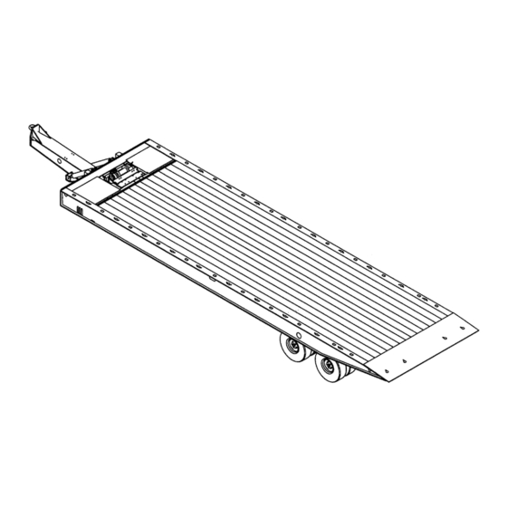
- Page 1 Model 345E Trailer Operator’s Manual LANDOLL CORPORATION 1900 North Street Marysville, Kansas 66508 (785) 562-5381 800-428-5655 ~ WWW.LANDOLL.COM F-563-0610 06/2010...
-
Page 3: Table Of Contents
Table of Contents Introduction Understanding Safety Statements ..........1-2 Standard Specifications Operating Instructions General . - Page 4 Maintenance Procedures ............4-1 Standard Torque Values .
-
Page 5: Introduction
Chapter 1 Introduction The Landoll Model 345E trailer is a quality product designed to give years of trouble free performance. By following each section of this manual, your system will perform as designed for you and your operation CHAPTER 1 gives basic instructions on the use of this manual. -
Page 6: Understanding Safety Statements
Make sure you read and understand the information contained in this manual and on the machine signs (decals) before you attempt to operate or maintain this vehicle. The safety statements contained in this manual relate to the operation of the Model 345E Trailer. F-563-0610 Edition... -
Page 7: Standard Specifications
Chapter 2 Standard Specifications CAPACITY* 40,000 LB. DISTRIBUTED, 30,000 LB. CONCENTRATED IN 10’ OVERALL LENGTH (WITH 48" HITCH): 35’-2" OVERALL WIDTH: 96" OR 102" WEIGHT (102" WIDE, SPRING SUSPENSION, 7’ HITCH, 12,000 LBS. WOOD DECK, 12M WINCH): HITCH: PINTLE HOOK W/ HYDRAULIC TILT LENGTH 48", 60"... - Page 8 STANDARD SPECIFICATIONS LANDOLL CORPORATION GENERAL TORQUE SPECIFICATIONS (REV. 4/97) THIS CHART PROVIDES TIGHTENING TORQUES FOR GENERAL PURPOSE APPLICATIONS WHEN SPECIAL TORQUES ARE NOT SPECIFIED ON PROCESS OR DRAWING. ASSEMBLY TORQUES APPLY TO PLATED NUTS AND CAPSCREWS ASSEMBLED WITHOUT SUPPLEMENTAL LUBRICATION (AS RECEIVED CONDITION). THEY DO NOT APPLY IF SPECIAL GRAPHITE MOLY-DISULFIDE OR OTHER EXTREME PRESSURE LUBRICANTS ARE USED.
- Page 9 STANDARD SPECIFICATIONS LANDOLL CORPORATION HYDRAULIC FITTING TORQUE SPECIFICATIONS JIC, ORS, & ORB (REV. 10/97) THIS CHART PROVIDES TIGHTENING TORQUES FOR HYDRAULIC FITTING APPLICATIONS WHEN SPECIAL TORQUES ARE NOT SPECIFIED ON PROCESS OR DRAWING. ASSEMBLY TORQUES APPLY TO PLATED CARBON STEEL AND STAINLESS STEEL FITTINGS ASSEMBLED WITHOUT SUPPLEMENTAL LUBRICATION (AS RECEIVED CONDITION) THEY DO NOT APPLY IF SPECIAL GRAPHITE MOLY-DISULFIDE OR OTHER EXTREME PRESSURE LUBRICANTS ARE USED.
- Page 10 STANDARD SPECIFICATIONS Page Intentionally Blank F-563-0610 Edition...
-
Page 11: Operating Instructions
Chapter 3 Operating Instructions General Anti-Lock Brake System (ABS) The Anti-Lock Brake System of the trailer is constant This section supplies information for operation of the powered by the auxiliary (blue) circuit of the seven way trailer. It describes and locates controls and gives general electrical connector, with backup power from the stop operation procedures. -
Page 12: Pre-Coupling Of Trailer And Truck
OPERATING INSTRUCTIONS Pre-Coupling of Trailer and Truck 4. If the trailer hydraulics are powered by the truck hydraulics clean the hydraulic quick couplers and 1. Slowly back the truck (towing vehicle) up to the front connect the trailer to the truck hydraulic couplers. If end of the trailer so the hitch of the trailer is centered trailer is equipped with auxiliary engine hydraulic with the truck. -
Page 13: Coupling Of The Towing Vehicle To The Trailer
OPERATING INSTRUCTIONS Coupling of the Towing Vehicle Connecting Towing Vehicle to the Trailer Services to the Trailer 1. Connect the electrical receptacle on the front of the DANGER trailer to the towing vehicle (See Figure 3-1.) Insure all lights function properly when energized by towing Keep all personnel clear of front, rear, and sides vehicle electrical action. -
Page 14: Towing Vehicle And Trailer Hook-Up And Check-Out
OPERATING INSTRUCTIONS Towing Vehicle and Trailer 2. Make a moving test of the trailer brakes at low, and medium speeds before traveling at highway speed. Hook-Up and Check-Out a. The Anti-Lock Brake System (ABS) warning lamp mounted at left rear side of the trailer ... -
Page 15: Parking The Trailer
OPERATING INSTRUCTIONS Parking the Trailer Uncoupling Towing Vehicle from Trailer 1. Position truck/trailer rig on a level, solid surface. 2. Set the PARKING BRAKE, not the trailer hand brake, 1. Park the trailer according to instructions in “Parking and check for proper brake holding. the Trailer”... -
Page 16: Winch Controls
OPERATING INSTRUCTIONS Winch Controls 1. The 12,000# WINCH CLUTCH HANDLE is on the curbside of the winch assembly (See Figure 3-2.) The 12,000 pound winch clutch handle has two DANGER positions that engage or disengage the winch spool: — DISENGAGE 1. -
Page 17: Axle Control Lever
OPERATING INSTRUCTIONS Axle Control Lever Trailer Tilt Lever The AXLE CONTROL LEVER is located on the front, The TRAILER TILT LEVER is located on the front lower lower deck of the driver’s side frame member (See deck of the driver’s side frame member (See Figure 3-3.) Figure 3-3.) It is the rear lever with three positions: It is the front lever with three positions: —... -
Page 18: Loading The Trailer
OPERATING INSTRUCTIONS Loading the Trailer WARNING 1. Practice all standard industrial safety standards (See In loading or unloading position, the approach Figure 3-4.) Do not load any payload that will plate should be resting on the ground. overload any component of the trailer or cause an unsafe condition. -
Page 19: Unloading The Trailer
OPERATING INSTRUCTIONS Unloading the Trailer WARNING The center of gravity of the load must be in front WARNING of the rear axle whenever the approach plate is Never tilt the trailer without the load properly not supported by the ground. Failure to do this restrained. - Page 20 OPERATING INSTRUCTIONS Figure 3-4: Steps for Loading and Unloading 3-10 F-563-0610 Edition...
- Page 21 OPERATING INSTRUCTIONS 1. Practice all standard industrial safety standards (See WARNING Figure 3-4.) 2. Park towing vehicle and trailer on relatively level When removing load, insure that the load is ground. steering straight so it does not maneuver off the 3.
-
Page 22: Auxiliary Hydraulic Power Engine Operation
OPERATING INSTRUCTIONS Auxiliary Hydraulic Power 2. The Engine Ignition Switch, Choke and Throttle are on the Engine Control Panel mounted on the driver’s Engine Operation side of the trailer (See Figure 3-5.) 3. The HYDRAULIC POWER SUPPLY ENGINE 1. The Hydraulic Power Supply Engine is used to power THROTTLE controls the speed at which the engine the hydraulic functions, should the tractor not be operates (See Figure 3-5.) It is a variable position... -
Page 23: Dock Leveler Control
OPERATING INSTRUCTIONS Figure 3-6: Dock Leveler Controls Dock Leveler Control 2. The DOCK LEVELER CONTROLS are located under the deck, on the driver’s side, between the 1. To activate the dock level hydraulic circuit, turn the axles (See Figure 3-6.) The front-most control lever on the driver’s side of the trailer bed near the adjusts the cylinder on the driver’s or street side of front up to the engage position. - Page 24 OPERATING INSTRUCTIONS Figure 3-7: Rear Impact Guard and Anti-Lock Brake System 3-14 F-563-0610 Edition...
-
Page 25: Rear Impact Guard System
OPERATING INSTRUCTIONS Rear Impact Guard System Anti-Lock Brake System (ABS) Vehicle standards FMVSS No. 224, Rear Impact Vehicle standards FMVSS No. 121, anti-lock brake Protection, requires all trailers manufactured after system requires all trailers with air brake systems to have January 26, 1998 shall be equipped with a rear impact ABS after March 1, 1998. -
Page 26: Remote Control (Option)
OPERATING INSTRUCTIONS Remote Control (Option) CAUTION 1. A wireless six function radio remote control is The auxiliary (blue) circuit is for powering the available (See Figure 3-8.) semitrailer ABS. This circuit must be hot when 2. The wireless radio remote has six momentary push the tractor key switch is on. -
Page 27: Cold Weather Operation
OPERATING INSTRUCTIONS RED ERROR CODE GREEN SIGNAL LIGHT LIGHT TRANSMITTER POWER REMOTE COVER TILT TILT DOWN WINCH WINCH 6 FUNCTION DECAL AXLE AXLE BACK AHEAD 345D remote control op Figure 3-8: Remote Control Cold Weather Operation Hot Weather Operation 1. Cold weather causes lubricants to congeal, insulation 1. - Page 28 OPERATING INSTRUCTIONS Page Intentionally Blank 3-18 F-563-0610 Edition...
-
Page 29: Maintenance And Lubrication
Maintenance and Lubrication Lubrication This section contains instructions necessary for proper maintenance of the trailer. The 345E trailer is designed Table 4-1 and Figure 4-1 details lubrication points and for years of service with minimal maintenance. However, intervals, method of application, and lubricant required, proper maintenance is important for durability and safe and illustrates the location of each part to be lubricated. - Page 30 MAINTENANCE AND LUBRICATION WINCH (12,000 LB ONLY) (3) SLACK ADJUSTERS CAMSHAFT BUSHINGS CAM FOLLOWERS REAR ROLLER (3) WINCH GEAR CASE (2) WINCH CABLES (4) ENGINE PACKAGE HYDRAULIC VIEW A-A RESERVOIR (1) CENTRALIZED GREASE SYSTEM ENGINE HUB OIL (5) CRANKCASE(6) BOTH SIDES PIVOT TUBE (3) PARK STANDS (3) DOCK LEVELER (3)
-
Page 31: Cleaning
MAINTENANCE AND LUBRICATION BRAND AND PRODUCT (WEIGHT AND/OR TYPE) LUBE SEASON AMOCO EXXON PHILLIPS TEXACO ALL YEAR Rycon MV HDX Plus 10W Magnus Oil Rando HD-AZ A KV 5w-20 SUMMER Permagear EP 460 Spartan 460 SAE Phil Gear Lube 460 Meropa 460 SAE SAE 140 SAE 140... -
Page 32: Hitch, Frame, And Deck
2. Frayed or unraveling wire must have the defective traffic, and properties. If any cracks or breaks are found, section removed and replaced with wire of the same contact a Landoll authorized service center for repairs. color and gauge. Seal all connections and insulate. Wood Deck Care 3. - Page 33 See Table 2-1 and Table 2-2 (Torque Specifications) for correct torque. c. See Table 4-1 (Lube Specification Chart) for recommended lubricant. d. Call Landoll Customer Services for procedures to replace. e. See Serial Number Plate on the front of the trailer for proper inflation requirements.
- Page 34 STOP STOP STOP STOP TURN TURN TAIL TAIL TAIL TAIL TAIL LICENSE TAIL LEFT RIGHT RIGHT LEFT LEFT LAMP RIGHT DS13 DS15 DS17 DS19 DS21 DS22 DS20 DS18 DS16 DS14 345d elect op Figure 4-2: 345E Wiring Diagram F-563-0610 Edition...
- Page 35 MAINTENANCE AND LUBRICATION 345d remote control schematic Figure 4-3: 345E Remote Control Wiring Diagram...
- Page 36 IDENTIFICATION RIGHT, RED WINCH OUT DS21 IDENTIFICATION LEFT, RED TILT UP DS22 IDENTIFICATION CENTER, RED TILT DOWN DS23 CONTROL PANEL DS24 ENGINE PANEL DS25 WORK LIGHT DS26 WORK LIGHT DS27 ABS MALFUNCTION INDICATOR, YELLOW Table 4-3: 345E Wiring Parts List F-563-0610 Edition...
-
Page 37: Suspension Maintenance
Neway; Second number listed is torque personnel. If the bushings need to be replaced required if bolt head designated with Holland Neway. contact a Landoll authorized service center or the Landoll factory for servicing. Air Ride Height Adjustment... -
Page 38: Alignment
5. Check the ride height to make sure it is correct. DANGER Consult Landoll Service Center if correct height cannot be obtained. To prevent a life threatening accident: 6. Loosen the 1/4" adjusting lock nut located on the 1. - Page 39 MAINTENANCE AND LUBRICATION Figure 4-5: Examples of Camber Figure 4-6: Checking Axle for Bend 4-11...
-
Page 40: Axle Alignment
MAINTENANCE AND LUBRICATION Figure 4-7: Checking Axle Alignment Axle Alignment Air Ride Suspension Axles The air ride suspension is aligned and adjusted at the Proper axle to pintle eye alignment is necessary to obtain factory and it should not be necessary to align the axles. straight tracking. -
Page 41: Brake System Maintenance
MAINTENANCE AND LUBRICATION Brake System Maintenance Spring Suspension Axles SPRING SUSPENSION TORQUE CHART WARNING 7/8” Use great care if wheels or brake drums must be Size 1” 7/8” U-Bolt 1/2” handled. They may be very hot and can cause serious injury. -
Page 42: Spring Air Brake
MAINTENANCE AND LUBRICATION Figure 4-9: Brake Lining Wear Spring Air Brake Uncaging the Power Spring in the Spring Chamber Check for faulty units. Check the condensation holes on 1. Chock the trailer wheels. the underside of the brake chambers to make sure they are open. -
Page 43: Tandem Relay Valve Maintenance
Contact when greasing the camshaft bushing. a Landoll authorized service center for servicing. 2. Install cam roller assemblies onto the brake shoes. 3. Install “D” shaped camshaft washer onto the Brake Assembly Maintenance camshaft. - Page 44 MAINTENANCE AND LUBRICATION Figure 4-10: Axle and Brake Assembly 4-16 F-563-0610 Edition...
-
Page 45: Automatic Slack Adjusters
MAINTENANCE AND LUBRICATION Automatic Slack Adjusters 5. The push rod stroke should be 1-1/2" to 2" with an 100 to 105 PSI service brake application. The trailers automatic slack adjusters provide the means 6. Measure the movement of the push rod from the for routine brake adjustment to compensate for lining completely released position to the applied position wear. - Page 46 MAINTENANCE AND LUBRICATION Replacing Slack Adjuster 7. Observe the guide pointer arrow: If the guide pointer is above the clevis pointer, adjust clevis CCW for alignment. CAUTION If the guide pointer is below the clevis pointer, adjust clevis CW for alignment. The installation guide must be used when installing or reinstalling automatic slack adjuster.
-
Page 47: Hub And Drum Maintenance
MAINTENANCE AND LUBRICATION Hub and Drum Maintenance 3. Replacement of the brake drum is required if any of the following conditions exist: a. The brake drum is cracked. WARNING b. The brake surface is heat checked, grooved or worn beyond the rebore limit or the maximum Failure to replace faulty brake drums will result in diameter. - Page 48 MAINTENANCE AND LUBRICATION Figure 4-12: Outboard Mount Hub and Drum Place the drum over the hub and brake shoes WARNING being careful not to damage the threads on the studs (See Figure 4-12.) Make sure the drum Failure to use the correct stud on the correct side seats flat against the hub flange and mates may cause loosening of the hub studs during properly with the hub pilot.
-
Page 49: Wheel Bearing Lubrication And Adjustment
MAINTENANCE AND LUBRICATION Wheel Bearing Lubrication and Adjustment Adjustment 1. With a drain pan under the hub cap, remove the hub cap assembly allowing oil to drain. With trailer sitting level, the oil level must be checked 2. Lift the wheel off of the ground. daily and maintained between the “ADD”... -
Page 50: Tire Maintenance
MAINTENANCE AND LUBRICATION Figure 4-13: Tire Inflation Examples Tire Maintenance Tire Inflation Tire inflation will cause tire to ground contact characteristics as shown in Figure 4-13. Tire inflation should be checked daily while the tire is cold, and during road stops. Checking the tire pressures while tires are hot will give a faulty increased pressure reading. -
Page 51: Mounting Tire And Wheel
MAINTENANCE AND LUBRICATION Figure 4-16: Mounting Tires and Wheels Mounting Tire and Wheel 1. Make sure that all mounting surfaces are clean and free of rust, dirt or paint. A wire brush may be used to clean these surfaces (See Figure 4-16.) 2. -
Page 52: Winches
MAINTENANCE AND LUBRICATION Winches Inspect the winch cable before and after every usage. If frayed wires, nicks, kinks, worn spots, breaks or any other sign of deterioration or damage is found, immediate replacement is mandatory before further usage. If the trailer is going to be out in the weather for any length of time, it is advisable to oil the winch cable to prevent untimely rusting and deterioration of the cable. -
Page 53: Troubleshooting
Chapter 5 Troubleshooting Electrical Most electrical system problems show up as a burned out light or fuse, or inoperative electrical component. Wiring, grounds, or components may be at fault. Locate the symptom in this section that best identifies your electrical problem. -
Page 54: Tires-Wheels-Suspension
TROUBLESHOOTING Tires-Wheels-Suspension • “Hydraulic System” on page 4-4 • “Alignment” on page 4-10 Most tire, wheel, and suspension related problems are • “Hub and Drum Maintenance” on page 4-19 due to excessive loads, extreme conditions, and improper • “Wheel Bearing Lubrication and Adjustment” on maintenance. -
Page 55: Brakes
TROUBLESHOOTING PROBLEM PROBABLE CAUSE SOLUTION BROKEN STUDS Over tightening Use correct torque when mounting (See “Standard Specifications” on page 2-1.) REPLACE BROKEN STUDS BEFORE USING THE SEMITRAILER! TRAILER TRACKING PROBLEMS: TRACKS TO ONE SIDE Axle alignment Re-align axle (See “Axle Alignment” on page 4-12.) TRACKS TO EITHER SIDE Broken or bent springs or equalizers... - Page 56 TROUBLESHOOTING PROBLEM PROBABLE CAUSE SOLUTION SINGLE BRAKE DRAGGING OR Broken internal brake component Locate and replace broken part (See LOCKED “Brake Assembly Maintenance” on page 4-15.) Flat spot on cam roller or cam shaft Replace and lubricate Improper adjustment Adjust slack adjusters (See “Automatic Slack Adjusters”...
-
Page 57: Brake Drums
TROUBLESHOOTING PROBLEM PROBABLE CAUSE SOLUTION BRAKES GRABBING Grease on brake linings Reline brakes Brake rigging binding Align brakes or replace bent parts Defective brake valve on tractor Repair or replace valve Defective relay emergency valve Repair or replace valve. Excessive leakage with brakes released. -
Page 58: Hydraulic System
TROUBLESHOOTING Hydraulic System Most hydraulic system failures follow the same pattern: a gradual or sudden loss of pressure or flow with a resulting loss of cylinder or motor power. Any one of the system’s components may be at fault. By following step-by-step procedures, the trouble can be located in a short time. -
Page 59: Dock Level Hydraulics
TROUBLESHOOTING PROBLEM PROBABLE CAUSE SOLUTION OVER HEATING OF OIL IN SYSTEM Oil passing through relief valve for Return control valve to neutral when not in excessive time Incorrect, low, dirty oil Use recommended oil (See Table 4-1). Fill reservoir with clean oil. Replace filter. Engine running too fast Reduce engine speed Excessive component internal leakage... - Page 60 TROUBLESHOOTING Notes: F-563-0610 Edition...
- Page 62 Equipment from Landoll Corporation is built to exacting standards ensured by ISO 9001 registration at all Landoll manufacturing facilities. Model 345E Trailer Operator’s Manual Re-Order Part Number F-563-0610 LANDOLL CORPORATION 1900 North Street Marysville, Kansas 66508 (785) 562-5381 800-428-5655 ~ WWW.LANDOLL.COM Copyright 2010.
Need help?
Do you have a question about the 345E and is the answer not in the manual?
Questions and answers