
Subscribe to Our Youtube Channel
Related Manuals for HETRONIC RX-HL Series


Summary of Contents for HETRONIC RX-HL Series
- Page 1 NSTALLATION NSTRUCTIONS RX-HL S ERIES ECEIVER www.hetronic.com YOUR #1 PARTNER IN RADIO REMOTE CONTROLS INST_BB_001.0 November 2007...
-
Page 2: Table Of Contents
ABLE OF ONTENTS Safety ........1 Safety Alerts ......1 Notations . -
Page 3: Safety
AFETY AFETY LERTS OSSIBLE OURCES OF ANGER The safety alert symbol is used in decals on the unit This device is part of a system that makes remote and with proper operation procedures in this control via radio signals possible. However, the manual. -
Page 4: Introduction
NTRODUCTION Thank you for purchasing the Hetronic radio remote EFORE PERATING YSTEM control system. Hetronic radio remote controls Confirm that installation of all your system provide outstanding remote control value, quality, components has been properly completed. performance and safety. ALWAYS confirm that the machine and radio ANUALS remote control Stop functions work properly. -
Page 5: About Your Receiver
ESCRIPTION For more information regarding expansion boards The RX 14-HL is an expandable receiver baseboard contact Hetronic or your dealer. that has been designed to work in conjunction with a variety of transmitters. See your transmitter documentation for detailed transmitter information. -
Page 6: Rx 14-Hl Features
• AC supply (120 to 240 Vac) or 48 Vac with relays, 2 SPDT power relays, and 1 Serial separate input Peripheral Interface (SPI) to connect various • Built-in Hetronic 70 pin quick disconnect expansion boards. connector • External antenna... -
Page 7: Mounting Your Receiver
OUNTING ECEIVER 1. Determine the receiver location, keeping in NOTE: If the receiver will be mounted inside of a mind the following conditions: control panel or other enclosure, see “Installing Your External Antenna (Optional)” • The receiver will be accessible and on page 7. -
Page 8: Installing Your Output Wiring
NSTALLING UTPUT IRING CAUTION: Assign a qualified technician to connect the wiring. Improper wiring connections may cause serious component damage and void the warranty. Output wiring must be properly connected for your specific requirements. Make all connections with good quality contacts or solder joints to ensure proper electrical contact. -
Page 9: Components
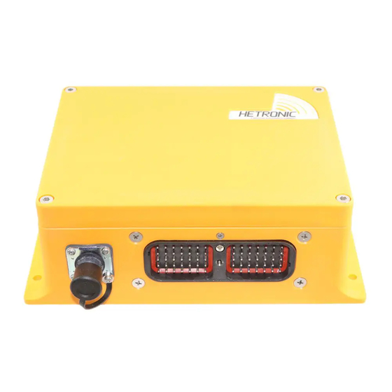
OMPONENTS ADMO1 ADMO2 11 12 ADMO1 ADMO2 Operation Signal Error Normal Figure 1: RX 14-HL Components Table 1: RX 14-HL Components 70 Pin Connector (X1) Antenna Port (used with transceiver only) Cable Control/Programming Port (X2) Expansion Board Platform Ground Fuse (6.3AL 250 V) Radio Frequency Module Stops (SPST relays) Scan Stop... -
Page 10: Accessories
CCESSORIES NSTALLING XTERNAL NTENNA PTIONAL CAUTION: Choose the correct antenna length for your application. Do not cut, splice, alter or coil your antenna or reception may be adversely affected. There are numerous configurations of external antennas. The following procedure explains how to install the external antenna commonly used with this receiver. -
Page 11: Specifications
PECIFICATIONS The specifications apply to all configurations using Weight and output specifications vary per standard the RX 14-HL baseboard unless otherwise noted. configuration. Table 1: Technical Specifications for All RX 14-HL Baseboard Configurations Housing Material PA + 30% Glass Fill Environmental IP 65 (Exceeds Nema 12/13) Protection... -
Page 12: Standard Configurations
TANDARD ONFIGURATIONS Includes the RX 14-HL baseboard Functionality and the following expansion boards Standard Weight Configurations REL-8 Inputs Outputs REL-8 GDAW-K6 PROP4-K4 Extension RX 14-HL 1.7 kg 4 Digital 14 Digital (Baseboard) (3.8 lbs) 1.8 kg 20 Digital RX 14-PT-HL 4 Digital (4.0 lbs) 1 Prop. -
Page 13: Forms And Additional Information
Hetronic assumes no responsibility for the correct The operator is responsible for understanding and installation of the radio remote control system. following all safety precautions in this and other applicable documentation. -
Page 14: Awg Metric Conversions
AWG M ETRIC ONVERSIONS Metric Equivalents Cable Size mm mm sq. 0.52 0.75 0.82 1.32 5.32 LOSSARY Acoustic signal A buzzer or other sound intended to be heard as an alert Analog signal Proportional - stepless or infinite control A transmitter that is secured to the front of the operator’s body by a belt, strap or Belly box breastplate/harness. -
Page 15: Abbreviations
BBREVIATIONS Metal Oxide Varistor type of surge Analog to digital conversion suppressor Analog channel (German: Analog Milliwatt Kanal) Ampere NiCd Nickel Cadmium American Wire Gauge NiMh Nickel Metal Hydrite Bits Per Second Programmable Logic Controller Central Processing Unit Phased Locked Loop DPST Double Pole Single Throw Press to operate... - Page 16 Hetronic. Technical information subject to change without notice. Hetronic reserves the right to discontinue, make changes to, and add improvements upon its products at any time without public notice or obligation. Hetronic disclaims liability for any claims or damages, whether regarding property, personal injury or death arising out of the use of unauthorized replacement parts or service.
Need help?
Do you have a question about the RX-HL Series and is the answer not in the manual?
Questions and answers