Table of Contents
Advertisement
Operator Manual
www.hetronic.com
YOUR #1 PARTNER IN RADIO REMOTE CONTROLS
Hetronic USA
4300 Highline Blvd., Bldg. A
Oklahoma City, OK 73108
405-946-3574
Fax 405-946-3564
© 2004 Hetronic, Inc.
All rights reserved. No part of this publication may be reproduced, transmitted, transcribed, stored in a retrieval
system, or translated into any language in any form by any means without the written permission of Hetronic.
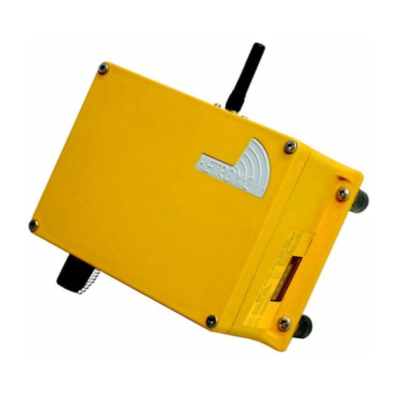
BMS-2 System
RX BMS2-PWM
RX BMS2-VC
Hetronic Canada
45 Sinclair Avenue
Halton Hills, Ontario L7G 4X4
+1-800-816-4459
Fax +1-905-702-0501
OPMN_BMS2_0001.0
12/04
Advertisement
Table of Contents

Subscribe to Our Youtube Channel
Related Manuals for HETRONIC RX BMS2-PWM


Summary of Contents for HETRONIC RX BMS2-PWM
- Page 1 © 2004 Hetronic, Inc. OPMN_BMS2_0001.0 All rights reserved. No part of this publication may be reproduced, transmitted, transcribed, stored in a retrieval 12/04 system, or translated into any language in any form by any means without the written permission of Hetronic.
-
Page 2: Table Of Contents
Function Speed Adjustment ....12 Install Receiver and Output Wiring ..7 Hetronic Proprietary Software ..13 Mount the Actuators (Optional) ..8 Frequency and Address Settings. -
Page 3: Introduction
Use only Hetronic replacement parts. The replacement transmitter types. For this reason, the photos or of any part with anything other than a Hetronic illustrations of transmitters in this manual may not show authorized replacement part may adversely affect the the transmitter purchased with this system. -
Page 4: System Components
10. Always have batteries in the battery charger to ensure the availability of fully charged batteries. The BMS-2 is the Hetronic designation for a receiver 11. Installation, setup and service must be performed with specific functions and capabilities. The system by authorized personnel only. -
Page 5: Safety
When the transmitter is turned on, it performs a • Low battery sends E-stop after time out self-test to be sure that the circuitry is within When the transmitter is turned off, the Time Out designated parameters. If an error is detected, the process begins. -
Page 6: Operation And Work Area Safety
OPERATION AND WORK AREA SAFETY TO STOP IN AN EMERGENCY The work area must be free from obstacles, debris or 1. Press the red "EMERGENCY STOP" pushbutton. other tripping hazards. Avoid uneven work areas and 2. Turn the key to "OFF". any rough terrain. -
Page 7: Mount The Actuators (Optional)
Supply voltage and ground wiring are crucial and must Antenna must Area must be be connected to reliable connecting circuitry. Do not be vertical free of use a chassis ground for this equipment. The ground (pointing up). obstructions wire must be connected directly to the vehicle battery negative post. -
Page 8: Operation
• Check rubber cuffs and pushbutton caps for wear transmitter. or damage. 16. Both the radio remote control and the machine IMPORTANT: Never operate a transmitter with worn or are now ready for operation. damaged parts. Replace immediately with only Hetronic parts. Contact Hetronic or your Dealer. -
Page 9: Emergency Stop
The proportional functions and speed ranges are set transmitter "OFF" when not in use. When the with the Hetronic proprietary software included with transmitter is not attached to the operator, the key your system. You can modify the adjustments at any switch should be removed and stored in a secure time. -
Page 10: System Features
Receiving correct signal, BMS-2 in E-Stop, no E-Stop from TX Example: 0 0 1 means the receiver is getting a valid control telegram, all joysticks are in neutral www.hetronic.com position, with E-Stop condition in receiver SYSTEM FEATURES x x 2... -
Page 11: Dead Man Function
1. Use the crane’s manual controls to raise the found in most Hetronic receivers. These functions boom from its rest. Extend the boom to a safe include power regulation, decoding the received signal, starting point. -
Page 12: Hetronic Proprietary Software
"-" to decrease speed. FREQUENCY AND ADDRESS SETTINGS For Program Pushbuttons (shown) - Adjust the Each Hetronic radio remote control system contains a speed of this function by using the program transmitter RF unit and a receiver RF unit. - Page 13 Operating the transmitter without its antenna could destroy the final stage of the RF module. DO NOT attempt to change the Hetronic pre-set frequency or the 16-bit address. Personal injury and property damage could result from transmission interference and may void the warranty.
-
Page 14: Troubleshooting
If the system will not respond to the steps below or the with the system. The Operational Status codes are Receiver Display indicates a failure, contact the shown in the Operation Section of this manual. Hetronic Service Department or your authorized dealer. PROBLEM PROBABLE CAUSE CORRECTION... - Page 15 PROBLEM PROBABLE CAUSE CORRECTION Transmitter is E-Stop switch engaged Pull out the E-Stop pushbutton and press transmitting (Power the Start/Horn pushbutton LED flashing), but Transmitter out of range Take the transmitter back into the range of crane/machine will not the receiver. Press the Start/Horn respond pushbutton.
- Page 16 Valve 8 error input (VC) 1 x x Output 1 (up to 8) activated, joystick not in E 4 0 CAN bus data timeout error (Hetronic and neutral position. System will not start if joystick HMF) is not in neutral position.
-
Page 17: Specifications
SPECIFICATIONS Model BMS-2 (Baseboard Module System) System GA 610 General Data Frequency 70 cm Band (Selectable 458.800 Mhz to 459.175 Mhz) or CS434 Range approx. 100 m ( 328 ft.) Address 20-bit - 1,000,000 possible Operating temperature -30° to +70° C (-22°... - Page 18 INSTALLATION AND SAFETY TEST DATA This for must be completed and signed by the person Hetronic assumes no responsibility for the correct responsible for installation of this radio remote control installation of the radio remote control system. The system. equipment operator must ensure that the radio remote control system and the crane/machine operate correctly together.
- Page 19 DEFINITIONS Acoustic signal A buzzer or other sound intended to be heard as an alert. Analog signal Proportional - stepless or infinite control Belly box A transmitter that is secured to the front of the operator’s body by a belt, strap or breastplate/harness.
-
Page 20: Abbreviations
ABBREVIATIONS Analog to digital conversion Analog channel (German: Analog Kanal) Ampere American Wire Gauge Bits per second Central Processing Unit Digital channel (German: Digital Kanal) Electromagnetic compatibility Electromagnetic immunity EPROM Electrical programmable read-only memory Frequency modulation Ground High frequency Kilohertz Light emitting diode Lift to operate Milliampere hours... -
Page 21: Warranty
F.O.B: Hetronic USA, Inc. Oklahoma City, Oklahoma Hetronic, Inc., hereafter referred to as Company, guarantees all items manufactured by it against any defects of material and/or workmanship for a period of one year from the date of shipment. Company makes NO OTHER WARRANTY, EXPRESSED OR IMPLIED, AS TO THE MERCHANTABILITY OR FITNESS OF THE ITEMS FOR THEIR INTENDED USE OR AS TO THEIR PERFORMANCE.
Need help?
Do you have a question about the RX BMS2-PWM and is the answer not in the manual?
Questions and answers