
Subscribe to Our Youtube Channel
Related Manuals for HETRONIC BMS-2 VC


Summary of Contents for HETRONIC BMS-2 VC
- Page 1 NSTALLATION NSTRUCTIONS BMS-2 R ECEIVERS PWM V ERSIONS www.hetronic.com Local But Global INST_BM_001.0 January 2008...
-
Page 2: Table Of Contents
General Description ....3 Standard Features (VC and PWM Models) 4 BMS-2 VC Standard Model Only ..4 BMS-2 PWM Standard Model Only ..4 Mounting Your Receiver . -
Page 3: Safety
AFETY AFETY LERTS OSSIBLE OURCES OF ANGER The safety alert symbol is used in decals on the unit This device is part of a system that makes remote and with proper operation procedures in this control via radio signals possible. However, the manual. -
Page 4: Introduction
NTRODUCTION Thank you for purchasing the Hetronic radio remote EFORE PERATING YSTEM control system. Hetronic radio remote controls Confirm that installation of all your system provide outstanding remote control value, quality, components has been properly completed. performance and safety. ALWAYS confirm that the machine and radio ANUALS remote control Stop functions work properly. -
Page 5: About Your Receiver
2 - Active E-Stop 2 x x - Analog Channel 2 active E x x x x 4 - Passive E-Stop ... up to Analog Channel 8 See your Technical Documentation for your Specific Codes. www.hetronic.com Figure 1: Receiver Display and Codes (Rotated) -
Page 6: Standard Features (Vc And Pwm Models)
• Expanded Self-diagnostics with 3-Segment LED Display • Back-up Cable Control Interface with Sure Seal Connector • 12-24Vdc supply power for DC applications • Built-in Hetronic 70 pin quick disconnect connector • External antenna BMS-2 VC S TANDARD ODEL •... -
Page 7: Mounting Your Receiver
OUNTING ECEIVER 1. Determine the receiver location, keeping in NOTE: If the receiver will be mounted inside of a mind the following conditions: control panel or other enclosure, see “Installing Your External Antenna (Optional)” • The receiver will be accessible and on page 7. -
Page 8: Installing Your Output Wiring
NSTALLING UTPUT IRING CAUTION: Assign a qualified technician to connect the wiring. Improper wiring connections may cause serious component damage and void the warranty. Output wiring must be properly connected for your specific requirements. Make all connections with good quality contacts or solder joints to ensure proper electrical contact. -
Page 9: Components
OMPONENTS Figure 1: BMS-2 Components (VC) Table 1: BMS-2 Components (VC) 70 Pin Connector (X1) Antenna Fuse (7.5Amp) Address Module (Stop Decoder) External Inputs Address Module (Main Decoder) 2-Pin Connector (output) CAN Termination (X2) RS232 Interface CAN Interface (X3) Terminal Block Status Indicator RF Module (A2) Internal Analog Outputs (X8) - Page 10 Figure 2: BMS-2 Components (PWM) Table 2: BMS-2 Components (PWM) 70 Pin Connector (X1) TTL Digital Outputs (X7) Fuse (7.5Amp) Antenna External Inputs Address Module (Stop Decoder) 2-Pin Connector (output) Address Module (Main Decoder) RS232 Interface CAN Termination (X2) Terminal Block CAN Interface (X3) RF Module (A2) Status Indicator...
-
Page 11: Accessories
CCESSORIES NSTALLING XTERNAL NTENNA PTIONAL CAUTION: Choose the correct antenna length for your application. Do not cut, splice, alter or coil your antenna or reception may be adversely affected. There are numerous configurations of external antennas. The following procedure explains how to install the external antenna commonly used with this receiver. -
Page 12: Specifications
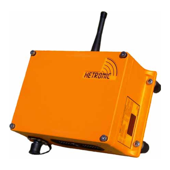
PECIFICATIONS Housing Material Impact resistant polymer composite Environmental IP 65 (Exceeds Nema 12/13) Protection Length: 10.4 in., 245 mm Dimensions Height: 6.3 in., 161 mm Depth: 4.4 in., 90 mm Weight 2,5 kg (5.5 lbs) Antenna External, TNC socket Voltage Supply 12 to 24 Vdc (-50% - +20%) Decoding Multiple bit scanning, self-monitoring... -
Page 13: Forms And Additional Information
Hetronic assumes no responsibility for the correct The operator is responsible for understanding and installation of the radio remote control system. following all safety precautions in this and other applicable documentation. -
Page 14: Awg Metric Conversions
AWG M ETRIC ONVERSIONS Metric Equivalents Cable Size mm mm sq. 0.52 0.75 0.82 1.32 5.32 LOSSARY Acoustic signal A buzzer or other sound intended to be heard as an alert Analog signal Proportional - stepless or infinite control A transmitter that is secured to the front of the operator’s body by a belt, strap or Belly box breastplate/harness. -
Page 15: Abbreviations
BBREVIATIONS Metal Oxide Varistor type of surge Analog to digital conversion suppressor Analog channel (German: Analog Milliwatt Kanal) Ampere NiCd Nickel Cadmium American Wire Gauge NiMh Nickel Metal Hydrite Bits Per Second Programmable Logic Controller Central Processing Unit Phased Locked Loop DPST Double Pole Single Throw Press to operate... - Page 16 Hetronic. Technical information subject to change without notice. Hetronic reserves the right to discontinue, make changes to, and add improvements upon its products at any time without public notice or obligation. Hetronic disclaims liability for any claims or damages, whether regarding property, personal injury or death arising out of the use of unauthorized replacement parts or service.
Need help?
Do you have a question about the BMS-2 VC and is the answer not in the manual?
Questions and answers