Table of Contents
Advertisement
Quick Links
Advertisement
Table of Contents

Related Manuals for Tektronix 511


Summary of Contents for Tektronix 511
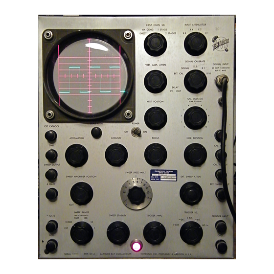
- Page 2 TYPE 511 CATHODE-RAY OSCILLOSCOPE INSTRUCTION MANUAL Ma nuf actu re rs o f C at h o d e - R a y a nd V id e o Test Instruments SUNSET H IG H W A Y AND BARNES ROAD P .O .B O X 831...
-
Page 3: Table Of Contents
CONTENTS GENERAL DESCRIPTION SECTION 1 Characteristics. Functions of Controls and Binding Posts. OPERATING INSTRUCTIONS SECTION 2 First-Time Operation. Sweep Circuit Adjustments--Adjustment of sweep stability. Function of trigger selector. Adjustment of trigger amplitude. Adjustment of sweep speed. Recurrent sweep. Single sweep. Sweep magnifier. Ext. sweep input. - Page 6 Oscilloscopes of all serial number ranges. The " Type 511A” designation is used throughout the text and will apply to the Type 511 and 511 AD un less noted otherwise by the insertion of serial number range notations. The Type 511 serial number range is 101 to 454 and the Type 511A is 455 and up.
-
Page 7: General Description
SECTION 1 GENERAL DESCRIPTION The Tektronix Type 511A Cathode-Ray Oscilloscope is a wide range, portable instrument, making possible the observa tion of a wide variety of electrical waveshapes. It is primarily intended for laboratory and shop use, in the development and testing of all types of electronic equipment. - Page 8 5 would otherwise produce excessive deflection times (S/N 101-454). or overload the amplifiers. DELAY (511 AD only) --Two position switch which VERT. AMPL. ATTEN.--500 ohm potentiometer permits the Type 1-AD-25 Delay Network to in cathode of cathode follower permits adjust...
- Page 9 EXPLANATIONS PANEL MARKINGS EXPLANATIONS PANEL MARKINGS VERT. POSITION--Twin potentiometers con vernier control setting sweep speed and dura trolling average potentials of vertical deflec tion within range indicated by SWEEP RANGE. tion plates and therefore the image position. (A single control, S/N 101-1405). CAL.
- Page 10 EXPLANATIONS PANEL MARKINGS EXPLANATIONS PANEL MARKINGS TRIGGER AMPL.— Potentiometer controlling position of TRIGGER SEL. switch. the bias applied to the trigger amplifier tube (V2) and thereby determining the amplitude DEFLECTION POLARITY---Three-position le of trigger signals applied to the multivibrator. ver switch mounted at the rear s which changes the V19 operating bias and the screen volt...
-
Page 11: Operating Instructions
SECTION 2 OPERATING INSTRUCTIONS The Type 511A may be operated in any normal indoor lo cation, or in the open if protected from moisture. If the in strument has been exposed to dampness, it should be left in a warm room until thoroughly dry before being placed in operation. - Page 12 6. Advance the SWEEP STABILITY control until 8. Advance the TRIGGER AMPL. control until a a sweep appears f then turn it back just under stable image of the calibrator waveshape this point. appears. The oscilloscope is now displaying the 50-60 cycle power line waveshape clipped (unclipped, 7.
- Page 13 The triggered sweep circuit used in the Type vibrator. After the SWEEP STABILITY is set 511 inherently provides for single sweep opera as described previously, and the TRIGGER SEL. tion. The beam is blanked out until the trigger simultaneously turns it on and starts the sweep.
-
Page 14: Sweep Input
EXT. Provision has been made for the connection SWEEP ATTEN. and a one stage push-pull of external sweep generators to the Type 511 A. amplifier. The entire system is DC coupled, This might be a sine wave oscillator for fre... - Page 15 In the 2 STAGES position a wide band pre If it is desired to observe pulses, the switch amplifier stage is inserted between the INPUT should be set in either the upward or downward ATTENUATOR and cathode follower. Since the position, corresponding to the deflection of the bandwidth and transient response of the two image on the cathode-ray tube.
- Page 16 peak-to-peak voltages: 0-1, 0-10, 0-100 v and eter is calibrated in peak-to-peak volts. If a are accurate to +or-10% with normal line sine wave is being measured, this may be con voltage (approximately 117 v). verted to R.M.S. by dividing by 2.828. The CAL.
-
Page 17: Circuit Description
CIRCUIT DESCRIPTION Major circuit number changes and improvements occurred in the Type 511 Oscilloscope starting with S/N 455. At this time the Type 511 designation changed to Type 511A. Numbers in paren thesis indicate the earlier values. If your oscilloscope has a se r... - Page 18 When the TRIGGER SEL. switch is in the -INT also the grid of V5, because of the coupling or +EXT. positions, signals are taken off the capacitor C7. The plate of V5 therefore rises cathode of VI and do not change in polarity. carrying with it the grid of V4 causing it to Therefore a positive impulse must be supplied conduct.
- Page 19 multivibrator pulse length. Gate Output Generator Unblanking Circuit V8 serves to isolate the gate output binding posts from the multivibrator. It receives a p osi During the waiting period the bias on the tive pulse on its grid of the same duration as cathode-ray tube is such that it is completely the sweep from the plate of V5 via the voltage cut off.
- Page 20 varied. Details of this adjustment may be found the signal on the grid of V11A, without change in Section 5. The two resistors R39.ll andR39.12 of polarity. The SWEEP MAGNIFIER POSITION connected in series are shunted across R20D1-9 potentiometer raises the potential on the grid to compensate for the plate circuit loads of V9.
- Page 21 In the upward position, the bias of V19 is de with this instrument, may be installed (S/N 101- creased, resulting in increased output of V19 454). Since the triggering of the Type 511 is and decreased output of VI8, thus permitting much more rapid than most oscilloscopes a delay greater undistorted upward deflection.
- Page 22 voltage divider R90 and R91 places the tube on rangement so that only one stage may be used the correct portion of its operating curve. So if desired. The first stage which is used only that the screen dissipation will not be excessive, in the 2 STAGES position of the INPUT CHAN.
- Page 23 are obtained by means of dropping resistors may be connected to any one of the six steps of R74 and R75 from the 6.3 v winding in o sc il the precision voltage divider. loscopes S/N 455-2405. In S/N 101-455 o sc il loscopes a 10 v (peak-to-peak) winding is s e ...
- Page 24 V28, as voltage standard. To see how Five rectifier tubes are used for the various DC supplies necessary to operate the Type 511. this circuit works consider what happens when the output voltage on the grid of the shunt...
- Page 25 same winding which is maintained at +125 v across C68. R152 and C69 provide additional to keep the heater-cathode potential of these filtering and reduce the voltage to about -1500 v. tubes within the rating. This supply also furnishes the bias current for the sweep coupling neons via R153 and R154.
- Page 27 This manual has been prepared to cover TEKTRONIX Type 511 Oscilloscopes of all serial number ranges. Diagrams, parts lists and text have been expanded to incorporate all instrument modifications adopted during the course of manufacture.
- Page 28 REMOVAL OF THE CASE dissipation and therefore faulty operation. A moderate amount of discoloration is normal. Set the oscilloscope face downward on a padded flat surface, remove the access panel jumper 3. Connections. Loose screws or nuts should plugs and the screws in the bottom, then lift be tightened.
- Page 29 If a centered spot now matched or selected tubes are not required in appears, abnormal deflection plate potentials the Type 511 A, some individual tubes which are indicated. Remove the short circuiting con perform normally in less critical circuits nections.
-
Page 30: Sweep Amplifier
supplies is abnormally high or low, the load Sweep Circuits current for that section may be measured to determine whether the defect lies within the Trouble in the sweep circuits is indicated when power supply or the external circuits. See the a spot on the CRT screen can be obtained, but schematic diagram for values. - Page 31 high, but should become normal after several from the factory and will be supplied with an hours operation. Occasionally, a Type NE2 lamp individually calibrated dial. will exhibit a tendency to oscillate. This condi tion is evidenced by a " spot" on the horizontal 3.
- Page 32 This control has an additional rotation stop capacitor to various circuit points, and observing punched in the cover; therefore the cover the result on the 511 Av s cathode-ray tube. should be removed and installed on the new control, unless a replacement is ordered from The following precautions should be observed the factory.
- Page 33 CAL. VOLTAGE MANUFACTURING TOLERANCES THE ELECTRONIC COMPONENTS AND Centered ASTIGMATISM TUBE CHARACTERISTICS. INTENSITY Centered POWER Centered FOCUS' Therefore, these tables should be used only Clockwise HOR. POSITION in conjunction with careful study of the Circuit SWEEP MAGNIFIER Description, Maintenance section and Schematic POSITION SWEEP SPEED MULT.
- Page 34 SWEEP STABILITY clockwise Gnd. + 110 SWEEP STABILITY counterclockwise + 210 Gnd. (cont.) 1.2. Gnd. Gnd. SWEEP STABILITY clockwise SWEEP STABILITY counterclockwise ..10 volt scale Gnd. Gnd. + 36 SWEEP STABILITY clockwise Gnd. + 67 SWEEP STABILITY counterclockwise Gnd.
- Page 35 Voltage Tube Gnd. 1,2. 50 volt scale Gnd. SWEEP STABILITY clock w ise..Gnd. + .25 SWEEP STABILITY counterclockwise 2.5 volt scale Gnd. + 225 S YEEP STABILITY clockwise SWEEP STABILTY counterclockwise Gnd. + 32 Gnd. 6.5 AC Gnd. + 65 SWEEP STABILITY clockwise SWEEP STABILITY counterclockwise Gnd.
- Page 36 Tube Voltage Gnd. 450 v S2C^ in 1 microsec. pos. Gnd. + 260 to 400 (cont.) depending on setting of R42 Gnd. 440 v S2C2in 1 microsec. pos. 1,3,5,7 Gnd. Gnd. 6.5 AC Gnd............. 10 volt scale Gnd. + 145' Gnd.
- Page 37 Tube Voltage + 160 Gnd. DEFLECTION POLARITY up Gnd. + 195 DEFLECTION POLARITY center Gnd. + 165 DEFLECTION POLARITY down Gnd. Gnd. + 110 DEFLECTION POLARITY up* Gnd. + 150 DEFLECTION POLARITY center* Gnd. + 200 DEFLECTION POLARITY down* Pin 14 6 .
- Page 38 Voltage Tube + 225 + 325 Gnd. + 225 Gnd. 6.5 AC Gnd. Gnd. Gnd. + 8 7 Gnd. + 89 Gnd. Gnd. 6.5 AC + 225 Gnd. + 137 Gnd. + 89 Gnd. -150 Gnd. Gnd. 50 volt scale Gnd.
- Page 39 Tube Pin No. Resistance Gnd. Gnd. Gnd. 1000 a Gnd. 470 k TRIGGER AMPL. clockwise 780 k TRIGGER AMPL. counterclockwise Gnd. 1000 a + 225 Gnd. + 225 10 k V2 pin 8 + 225 10 k Gnd. Gnd. V2 pin 8 + 225 10 k Gnd.
- Page 40 Resistance Tube Pin No. (S/N2869 and up) -140 35 meg Gnd. 2,3,7 Gnd. (S/N845-2868) Gnd. Gnd. + 225 V6 pin 2 Gnd. 10 k (S/N2869 and up) + 225 14.7 k V7.1 -140 65 k + 225 70 k 3,4,5 Gnd.
- Page 41 Resistance Tube Pin No. Gnd. 35 meg Gnd. Gnd. Gnd. VI2 pin 5 180 a -140 11 k V14 pin 2 900 £ 2 Gnd. Gnd. + 450 25 k HOR. POSITION clockwise Gnd. Gnd. 90 k HOR. POSITION counterclockwise -140 11 k Gnd.
- Page 42 Tube Resistance Pin No. 440 a Gnd. Gnd. Gnd. R116 counterclockwise Gnd. 290 k 1.3 meg R116 clockwise Gnd. S9 in center position + 225 2.2 k S9 in up or down position + 225 4.4 k 2.8 k + 225 VI8 pin 1 Gnd.
- Page 43 Tube Pin No. R esistan ce + 450 V21 pin 7 (cont.) Gnd. 550 k + 225 T1 term. 22 T1 term. 23 V25 pin 1 + 225 43 k + 450 130 k V22 pin 8 470 k + 225 + 225 Gnd.
- Page 44 TRANSFORMER CONTINUITY (Measured with leads disconnected) Terminals Ohms Resistance (2 0 ° C) 1 to 3 2 to 4 5 to 6 7 to 8 147. 150. 8 to 9 10 to 1 1 12 to 13 14 to 15 10.8 15 to 16 10.9...
- Page 45 DEFLECTION POLARITY SELECTOR WAVEFORMS Normal operation of this circuit for observation of pulses is shown in the following photographs. The sawtooth pulse has a duration of 1 millisecond and a 60 cycle repetition rate. Fig. 4-2. Same pulse with DEFLECTION PO Fig.
-
Page 46: Power Supply
POWER SUPPLY WAVEFORMS Fig. 4.5 60-cycle ripple of -140 volt rectifier Fig. 4-6. 120-cycle ripple of+225 volt rectifier output at V22 cathode and + 450-volt output at V24 plate. Amplitude 12 rectifier output at V21 cathode. Am volts. plitude 15 volts. Fig. - Page 47 Fig. 4-12. Multivibrator waveform at V5 plate, Fig. 4-11. Multivibrator waveform at V5 grid, controls set for 10 jisec recurrent controls set for 10 p sec recurrent sweep. Amplitude 160 volts. sweep. Amplitude 85 volts. Fig. 4-14. Waveform at -GATE, controls set Fig.
- Page 48 Fig. 4-19. Unblanking pulse at V7 cathode, 1 Fig. 4-20. Waveform at V9 grid, 10 p sec re p sec recurrent sweep. Amplitude current sweep. Amplitude 50 volts. 65 volts. Exposure made under same condi tions as figures 4-8, 4-9, 4-10, and 4-11.
- Page 49 Fig. 4-25. Amplified sweep sawtooth of X2 de Fig. 4-26. 1 iisec negative pulse at VI grid flection plate, 10 (isec recurrent from either video amplifier or TRIG sweep. Amplitude 200 volts. GER INPUT. Amplitude .5 volt. Fig. 4-27. The same pulse at V2 grid. Negative Fig.
-
Page 50: Adjustments
Fig. 4-31. Response to 50-cycle square wave Fig. 4-32. Normal response to 1 megacycle when low-frequency compensation is square wave, insufficient s also indicating need for L.F. adjustment. Fig. 4-33. Response to 1 megacycle square wave Fig. 4-34. Response to a 1 megacycle square showing overshoot due to excessive wave showing the effect of insuf... - Page 51 Fig. 4-37. Response to 1 kilocycle square wave Fig. 4-38. Positively clipped sine wave at pins with the input attenuator or probe 2, 6, and 7 of Calibrator Limiter, under compensated. VI6.1. Amplitude approximately 300 volts depending upon line voltage. (S/N 2406 and up).
- Page 53 SECTION 5 ADJUSTMENTS OPERATION ON 210-250 VOLT LINE ADJUSTMENT OF SWEEP-SPEED CALIBRA (S/N 455 and up) TION The power transformer of the Type 511A is If the Cathode-Ray Tube is replaced, or if wound with two 115 volt primaries. When the the Sweep Amplifier tubes VI3 and VI4 change instrument leaves the factory the primaries are their characteristics, the indicated sweep speeds...
- Page 54 (right front on attenuator), using a 50 v from 1 to 50 volts (peak-to-peak). (25 v, S/N 101-454) signal. The Tektronix Type 104A and Type 105 Square ADJUSTMENT OF VERTICAL AMPLIFIER H.F. Wave Generators are suitable for this purpose. RESPONSE If a Tektronix Oscilloscope is available, its square wave calibrator may be used.
- Page 55 4. Increase the inductance of L8 until a slight SEL. in the DIRECT position. The Tektronix overshoot appears. Type 104A and Type 105 Square Wave Genera tors provide a suitable signal source for this 5. Adjust L7 and L9 (readjust L8 slightly if adjustment.
- Page 56 The following available photographs cover instrument S/N 845 and up, the P510 probe and the P510Aprobe. Instruments S/N 101-845 are similar in appearance and these photographs will serve as a useful maintenance aid. Fig. 5-4. P510 Input Probe disassembled.
- Page 57 C A B L E IN P U T 10 MEG. SH U NTED W H EN C A B L E 15 T E R M IN A T E D W IT H A O jjljiP 3*12.>tju.F C E R . VAR. EOOV 9 MEG.
- Page 58 Fig. 5-6. Interior view, right front side. (S/N 845-1405) TYPE 511-A, 511-AD SECTION 4, PAGE 22...
- Page 59 NOTE: Picture is applicable to S/N1406 and up. Changes and additions made after S/N 1406 are indicated by boxed cir cuit numbers. See parts list for effective serial numbers.
- Page 64 NOTE--Picture is applicable to S/N1454 and above. Changes and additions made after S/N1454 are indicated by boxed c ir cuit numbers. See parts list for effective serial numbers. Fig. 5-12. Sweep chassis, bottom view.
- Page 65 NOTE--Picture is applicable to S/N-1454 and above. Changes and additions made after S/N1454 are indicated by boxed c ir cuit numbers. See parts list for effective serial numbers. Fig. 5-13. Sweep C h a ssisf top view.
- Page 66 Fig. 5-14. Video Amplifier, top Fig. 5-15. Video Am plifier, bottom, (S/N 845-1459) (S/N 845-1459)
- Page 67 » NOTE Picture is applicable to S/N1460 and db above. Changes and additions made after S/N@ ;f| | ^ 1460 are indicated by boxed circuit numbers, See parts list for effective serial n u m b e^ s.^ ^ ^ ^ 7 |R 7 5 .4 -|—...
- Page 68 Fig. 5-18. Power Supply, bottom view (S/N 845-1629) F ig. 5-19. P o w e r Supply, top view. (S/N 845-1629)
- Page 69 NOTE--Picture is applicable to S/N1630 and above. Changes and additions made after S/N1630 are indicated by boxed circuit numbers. See parts list for effective serial numbers.
- Page 70 T OP VIEW BOTTOM VIEW Fig. 5-22. Vertical Attenuator, top. Fig. 5-23. Vertical Attenuator, bottom. (S/N 845 and up) (S/N 845 and U P) Fig. 5-24. Deflection Polarity Switch and Terminal Board. (S/N 845 and up)
- Page 71 Fig. 5-25. Delay Network, left view. (S/N 845 and up) Fig. 5-26. Delay Network, right view. (S/N 845 and up)
- Page 72 12-28-50 TEKTRONIX , INC. Fig. 5-27 SN 845 and up...
- Page 73 SECTION 6 PARTS LIST COM PONENT SU B ST IT U T IO N Due to procurement difficulties, some of the components in any particular instrument may vary slightly from the values shown in this manual. In some cases two or more parts were substituted for one.
- Page 74 CAPACITORS 101 and up .01 jL tf Fixed + or-20% 400 v 285-510 101-454 .05 /xf Fixed 600 v Use 285-520 455 and up .01 jL tf Fixed 400 v 285-510 101-454X .1 jL tf Fixed 25 v Use 285-526 and clamp 343-006 C4A, B 101 and up...
- Page 75 -20+ 50% +Note: S/N's 101-454, order 295-027 for C15B, C, D, and E. For S/N's 455-5585, order 040-022, installing Tektronix mf'd. timing series after Mod. Kit is installed. For C15B, order 291-018; for C15C, D, and E, order 291-020. *C15C, D and E are all contained in one unit; Tektronix mf'd. timing capacitors.
- Page 76 101-454 .001 iif Fixed Mica 500 v 283-527 455-844 500 pjuf Fixed Mica 500 v Use 283-523 470 [ifif Fixed Mica 845-1699 500 v 283-522 300 (ifif 1700-1979 Fixed Mica 500 v Use 283-518 330 ppf 1980-5099 Fixed Mica 500 v 283-518 5100 and up 220 iijif...
- Page 77 101-454 Var. 4-30 jL tjL L f Cer. 500 v Use 281-010 455-862 5-20 jifif Var. Cer. 500 v Use 281-010 863 and up 4.5-25 pjtif Var. Cer. 500 v 281-010 Fixed 400 v 101-759 .1 jif 281-526 760 and up .1 jtif Fixed 600 v...
- Page 78 101-1496 .1 pf Fixed 600 v 285-528 1497 and up .1 fit Fixed 400 v 285-526 X4817 and up .047 iif Fixed 400 v 285-519 Fixed 101 and up .1 [if 2000 v 285-530 Fixed 2000 v 101 and up .1 pf 285-530 101 and up...
- Page 79 FUSES 3 amp. Slo-Blo 101-5341 159-007 5342 and up 3 AG 3 amp. Slo -Bio 159-005 INDUCTORS Fixed Use 108-020 101-454 35 ph 455-844 35 ph Fixed Mod. with 845-4410X 30 ph Fixed Rl.l, R2.1, R5.1 Fixed L l.l X4411 and up 7 ph 108-020 101-454...
- Page 80 RESISTORS 470 k 1/2 w 101 and up Fixed Comp. 302-474 Rl.l XI454 and up 47 ft 1/2 w Fixed Comp. 302-470 101-4410X 1.5 k Fixed Comp. 304-152 R2.1 X4411 and up 560 ft 1/2 w Fixed Comp. 302-561 101 and up 1/2 w Fixed Comp.
- Page 81 101 and up 220 k 1/2 w Fixed Comp. 302-224 101 and up 1/2 w Fixed Comp. 47 Q , 302-470 101-454 2x2 meg Var. Comp. R20A X455-1405X 2 meg Var. Comp. -10+20% Use Mod. Kit X455-1405X 2 meg Var. Comp.
- Page 82 Fixed Comp. X455 and up 4.7 k 306-472 101 and up 470 k 1/2 w Fixed Comp. 302-474 101 and up 470 k 1/2 w Fixed Comp. 302-474 101 and up 10 k Fixed Comp. 304-103 101 and up 10 k Fixed Comp.
- Page 83 Fixed Comp. 10 k 101-2868X 304-103 Comp. R48.1 18 k Fixed X2869 and up 306-183 10 k Fixed Comp. 101-2868X 304-103 Comp. 101-454 8.2 k 1/2 w Fixed 302-822 Fixed Comp. 270 k 1/2 w 455 and up 302-274 Comp. 101-555 330 k 1/2 w...
- Page 84 101-538 Fixed 4.7 k Comp. 10% Mod. W/C15AA, R44 # R59,and R63. Use 304-122 539 and up 1.2 k Fixed Comp. 304-122 101-538 30 k 10 w Fixed Mod. w/C15AA, R44, R59, R62. Use 308-026 539 and up 25 k 10 w Fixed 308-026...
- Page 85 R75.5 X2406 and up 27 k 1/2 w Fixed Comp. 302-273 101-2405X Var. Use Mod. Kit 040-015 X2406-5099 20 k 1/2 w Var. Use 312-003 R76.1 5100 and up 20 k Var. 312-003 R76.2 X2406 and up 13.23 k 1/2 w F ixed Prec.
- Page 86 680 a R93.1 X845-2867 Fixed Comp. Selected Use 312-534 560 £ 2 2868 and up Fixed Comp. Selected* 312-534 560 £ 2 R93.2 X845-2867 Fixed Comp. Selected Use 312-534 560 £ 2 2868 and up Fixed Comp. Selected** 312-534 101 and up 47 £...
- Page 87 Use 312-521 2869-5099X 470 k 1/2 w Fixed Comp. 312-521 -6%-10% R120.1 X845-2868 10 k 1/2 w Fixed Comp. Use 312-511 2869-5099X 10 k 1/2 w Fixed Comp. 312-511 -5%+10% R120.2 X845-2868 10 k 1/2 w Fixed Comp. Use 312-511...
- Page 88 R120.3 X845-2868 56 k 1/2 w Fixed Comp. Use 312-514 2869-5099X 56 k 1/2 w Fixed Comp. + 6%+10% 312-514 220 £ 2 101-454 Fixed Comp. R121* Use 312-544 455 and up 220 £ 2 Fixed Comp. Selected* 312-544 R122* 101-454 220 £...
- Page 89 R136 101 and up 1.5 meg 1/2 w Fixed Comp. 302-155 101-454 1 meg 1/2 w Fixed Comp. 302-105 R137 455-844 1.5 meg Fixed Comp. 1/2 w 302-155 845 and up 1 meg 1/2 w Fixed Comp. 302-105 101 and up 120 k 1/2 w Fixed...
- Page 90 R161 101-454 10 k Fixed Comp. 304-103 455 and up 270 k 1/2 w Fixed Comp. 302-274 101-454 R162 10 k Fixed Comp. 304-103 470 k 455 and up 1/2 w Fixed Comp. 302-474 101-454 470 k R163 1/2 w Fixed Comp.
- Page 91 260-025 TRANSFORMERS Some of the earlier 511 T-l transformers had an additional 6.3 volt secondary not shown on the diagram. Later transformers eliminated this winding, supplying all filament voltages from T-2. If replacement is necessary, determine whether both transformers supply the filament voltages;...
- Page 92 455 and up Primary: 170 v, tapped at 25 v, approx., 2 KC. 120-016 OR 120-015 for instruments with IB 3 HV rectifiers Secondaries: 1250 v , at 1 ma. 1.4 v , .2 a., connected to 1250 v winding 1.4 v , .2 a., insulated for 1500 v DC VACUUM TUBES 101 and up...
- Page 93 101-454 154-086 455 and up 154-035 101-454 154-085 455 and up 5V4G 154-008 101-454 154-085 455 and up 5V4G 154-008 101-454 154-086 455 and up 154-035 101-454 154-090 455 and up 6AQ5 154-017 101-454 154-003 455 and up 6AU6 154-022 101-454 6SJ7 154-088...
- Page 94 DELAY L IN E P A R T S L IS T CAPACITORS 500 v 281-007 101-5099X 3-12 iifif Var. Cer. C l to C4 281-506 CIA to C23A 101-5099X 500 v 12 pjLif Fixed Cer. 281-005 101-5099X 500 v C5 to C23 1.5-7 tijif Var.
- Page 95 By this method, random pulses may be observed. ADJUSTMENT AND MAINTENANCE The Type 511 AD Oscilloscope includes a fac tory-installed Type l-AD-25 Delay Network. If the Vert. Ampl. Atten. potentiometer,R107, or the limiting resistor, R108, are replaced,...
- Page 96 In case the first portion is lower, it will (R202, S/N510 and up). be necessary to increase the value of the shunt resistor. Remove the delay network cover and CAUTION: DO NOT DISTURB THE AD install a 1/2 watt resistor of suitable value JUSTMENT OF THE VARIABLE CAPA...
- Page 99 II -12-51 BLOCK DIAGRAM TYPE 5IIAD CATHODE-RAY O S C ILLO S C O P E io i...
- Page 100 TRIGGER SELECTOR 52 SWEEP RANGE S6 SWEEP MAGNIFIER TYPE 511 OSCILLOSCOPE SW E E P S / N 101-4 S 4 S E E P A R T S L IS T TO* EARLIER C HA N E L S...
- Page 102 SWEEP MAGNIFIER SWEEP AMPLIFIER...
- Page 103 TY PE 511 CATHODE RAY O SCIL L O SCO PE VERTICAL AMPLIFIER CIRCUIT S /N 1 0 1 -4 5 4 VERTICAL AMPLIFIER CIRCUIT S /N 4 5 5 - 8 4 4...
- Page 104 CAPACITOR VALUES LESS TH* I I ARE MFDS. AVERAGE SUPPLY CURRENT AT VALUES I AND GREATER ARE IMFDS,UNLESS CHASSIS TERMINAL BLOCK: OTHERWISE MARKED. -140 V . SUPPLY 0.3 M A. + 225 V . SUPPLY 1 2 8 M A . VERTICAL AMPLIFIER TYPE 511A OSCILLOSCOPE...
- Page 105 TYPE 5IIA D CATHODE-RAY OSCILLOSCOPE S/N 2406 4 UP...
- Page 106 -*-2 2 5 V VERTICAL AMPLIFIER...
- Page 107 TYPE 511 CATHODE RAY OSCILLOSCOPE POWER SUPPLY 101-454...
- Page 108 TO S7 3 A. 117 V 6 0 ~ APR. 1949 455-2405...
- Page 109 POWER SUPPLY TYPE 5 1 1 AD CATHODE-RAY OSCILLOSCOPE S /N 2 4 0 6 a UP...
- Page 110 V 32 BELOW S/N 3 3 50 S EE P A R T S L I S T FOR E AR LI ER VALUES OF PA RTS SHOWN IN RED. TYPE SHAD CATHODE-RAY OSCILLOSCOPE 2 4 0 6 ^ U P...
- Page 111 □...
- Page 112 S /N 4 5 5 - 5 0 9 9 NOTE: L-l TO L-12 INCLUSIVE COAXIALLY WOUND ON THE SAME COIL FORM. L -I3 T 0 L-23 TYPE ID 25 DELAY NETWORK, S/N 1 0 1 -4 5 4 , IS THE SAME AS TYPE I AD 25 EXCEPT THAT S I...
Need help?
Do you have a question about the 511 and is the answer not in the manual?
Questions and answers