
Related Manuals for Tektronix 511A


Summary of Contents for Tektronix 511A
- Page 3 YPE 51 1 A YPE 511AD OSCILLOSCOPE NSTRUCT ON MANUAL anufacturers of Cathode-Ray and Video Test Instruments 712 S. E. Hawthorne Blvd. Portland 14, Oregon - EAst 6197 - Cables: Tektronix...
- Page 4 SEC ION IV. MAIN ENANCE AND ABLE OF CON EN S ADJUS MEN . MAIN ENANCE. SEC ION I. Removal of Case. General Description. Cleaning. Characteristics. Inspection. Functions of Controls and Binding Posts. rouble Analyzing and Repair. SEC ION II . OPERA ING INS RUC IONS. General.
- Page 5 SWEEP SPEED MUL IPLIER MODIFICA ION The dual 2 megohm potentiometer Sweep Speed Mult, control formerly employed in the Type 511 - D oscilloscope has been replaced with a combination con sisting of a ten position step control and a separate variable control.
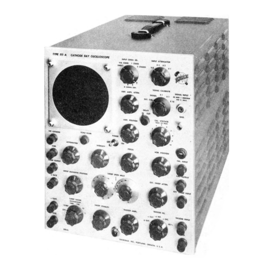
- Page 7 GENERAL DESCRIP ION 1 Stage, 2.7 V per cm maximum, 40 V per cm mini mum. The Tektronix Type 511- Cathode Ray Oscillo 2 Stages, .27 V per cm maximum, 4 V per cm mini scope is a wide range, portable instrument, making mum.
- Page 8 Potentiometer controlling the average INTENSITY PANEL MARKINGS EXPLANA ION grid voltage of the CRT and thereby the brightness of the image. INPUT CH N. Gang switch permitting the SIGN L SEL. INPUT binding post to be connected to On-off switch in the C line voltage POWER the vertical deflection plates either di ...
- Page 9 - G TE Binding post for connection via .1 ca TRIGGER SEL. Switch determining source and polari pacitor to the plate of (V8). This fur ty of trigger voltage. nishes a 40 V negative pulse of the same duration as the sweep.
- Page 11 CAU ION — DO NOT LLOW THIS SPOT SECTION II TO BE EXCESSIVELY BRIGHT OR RE M IN FOR LONG IN ONE POSITION. OPERA ING INS RUC IONS dvance the SWEEP ST BILITY control until a The Type 511- may be operated in any normal in ...
- Page 12 RECURREN SWEEP NOTE — When using the internal trigger im pulses to view fundamental frequencies In case it is desirable to have a sweep without using any sort of trigger, merely advance the SWEEP ST BILI above about 2mc it will be necessary to TY control until a stable sweep is obtained.
-
Page 13: Video Amplifier
With the EXT. SWEEP TTEN. fully clockwise the de creasing L6, and readjusting L7, L8, L9, and L 10 , but flection sensitivity is approximately 1.5 volts per cm DC overshoot will occur on steep wave fronts. With opti or peak to peak C. - Page 14 by 2.828. If a voltmeter is used to measure the C L. CALIBRA ION OUTPUT, remember to multiply its R.M.S. by 2.828 to ob While the cathode ray oscilloscope is usually em tain a peak to peak reading. ployed only as a qualitative rather than a quantitative device, it is the only instrument capable of making many CAU ION —...
- Page 15 trigger amplifier V2 requires a positive impulse on its SECTION III grid to provide the correct trigger to the multivibrator. When the TRIGGER SEL. switch is in the +INT. or +EXT. positions, signals are taken off the cathode of CIRCUI DESCRIP ION V 1 and do not change in polarity.
-
Page 16: Sweep Magnifier
To cover a range of sweep time from .1 sec to 1 micro provide a continuous variation in sweep speed of from second, C7 has five values as selected by the SWEEP less than .1 sec to 1 microsecond for 10 cm sweep. In R NGE switch. - Page 17 plifier which does this uses a cathode coupled circuit CAU ION — LTHOUGH THE PROBE IN consisting of the triode connected 6 U6 tubes V13 and TRODUCES SIGN L TTENU TION V 1 4. The action of this circuit is the same as described OF 10 TIMES, IT SHOULD NOT BE CON ...
-
Page 18: Power Supply
V27 and thus de to permit the insertion of a Tektronix Type 1 D25 Delay creases the output voltage. If a decrease in line voltage and increase in load current tend to decrease the out ... - Page 19 SECTION IV lar capacitors may drip if the instrument has been over heated by operating in a restricted space. This condition usually does not indicate replacement. Composition re sistors should be checked for serious discoloration, MAIN ENANCE AND ADJUS MEN which would indicate excessive dissipation and there ...
- Page 20 measure the voltage between each CRT deflection plate may be used if available. This method is explained in detail under servicing instructions for each chassis. and ground, which should be within ±60 volts. The Since a large percentage of troubles experienced will average potential of both horizontal (X) plates, or both likely be caused by defective tubes, it is advisable to vertical (Y) plates, should be within ±40 volts of ground...
- Page 21 Sweep Circuits sweep speed), V9 is known to be good, and circuit volt ages appear normal, remove V9 and measure the volt Trouble in the sweep circuits is indicated when a spot age at terminal 4 of V9 socket, which should be between on the CRT screen can be obtained, but advancing the + 5 and +30 volts.
- Page 22 If triggering is erratic, it is desirable to first eliminate C44, as explained in the " djust of Input ttenuator" the possibility that instability of the signal being ob section. If satisfactory waveshape cannot be obtained, served is the cause. Possible internal causes are: arcing try another 6 G7.
- Page 23 Voltage and Continuity Tables INPUT CH N. SEL ......2 Stages INPUT TTENU TOR ....X 1 VERT. MPL. TTEN ....Clockwise SIGN L C LIBR TE ....Signal VERT. POSITION ......Centered CAU ION — THE POTENTI LS ND RE C L.
- Page 24 Tube Voltage Gnd. + . 5 Gnd. SWEEP ST BILITY clockwise Gnd. SWEEP ST BILITY counter clockwise Gnd. 6.5 C Gnd. Gnd. Gnd. Gnd. 6.5 C Gnd. +225 Gnd. SWEEP ST BILITY clockwise Gnd. SWEEP ST BILITY counter clockwise Gnd. SWEEP ST BILITY clockwise Gnd.
- Page 25 / r oltage Tube Gnd. 1,4, 5 + 450 V 1 5 pin 4 6.5 C Gnd. + 230 to depending on setting of R42 + 390 S2C 2 in 1 microsec. pos. Gnd. 450 V Gnd. + 260 to depending on setting of R42 + 400 Gnd.
- Page 26 Tube Pin Voltage V23, pin 8 5.2 C Gnd. 280 C Gnd. +325 Gnd. -335 V24, pin 4 6.5 C Gnd. 280 C + 450 Gnd. +450 V25, term. 3 6.5 C Gnd. +680 + 225 -1.3 + 225 V26, pin 4 6.5 C +450 +225...
- Page 27 Tube Pin No. Resistance Gnd. Gnd. Gnd. 1000 Gnd. 470K TRIGGER MPL. clockwise 780K TRIGGER MPL. counter clockwise Gnd. 1000 +225 Gnd. +225 V2 pin 8 +225 Gnd. Gnd. V2 pin 8 +225 Gnd. Gnd. Gnd. Gnd. SWEEP ST BILITY clockwise +225 SWEEP ST BILITY clockwise Gnd.
- Page 28 Tube Pin No. Resistance Gnd. Gnd. Gnd. -140 + 225 Gnd. +225 Gnd. Gnd. infinite Gnd. Gnd. +225 V9 pin 8 Gnd. V 1 1 +225 +225 14.7K Gnd. Gnd. Gnd. 8.2K SWEEP M GNIFIER POSITION out Gnd. Gnd. Gnd. Gnd.
- Page 29 Tube Pin No. Resistance Gnd. Gnd. Gnd. Gnd. 290K R-116 counter clockwise Gnd. 1.3M R-116 clockwise +225 2.2K S9 in center position +225 4.4K S9 in up or down position +225 2.8K V18 pin 1 Gnd. Gnd. Gnd. 470K V18 pin 6 +225 2.8K T 1 term.
- Page 30 Tube Pin No. Resistance V28 pin 2 Gnd. Gnd. -140 Gnd. 100K Gnd. Gnd. Gnd. +225 +225 1,3,4, 5, 6, 7, Gnd. V32 pin 1 V33 pin 3 1,3, 4,5 Gnd. 6, 7,8 1.3K V33 pin 1 Gnd. RANSFORMER CON INUI Y (Measured with leads disconnected) T2 (Measured with V32 and V33 removed from sockets) Ohms Resistance...
- Page 31 Waveform Photographs The following photographs are provided to facilitate 1. Loading effect of the test oscilloscope. servicing of the Type 511- and will prove especially 2. Non-linearity of the test oscilloscope. useful if another oscilloscope is available to observe the waveforms of the circuits being tested.
- Page 32 POWER SUPPLY WAVEFORMS Fig. 5. 60 cycle ripple of — 140 volt rectifier output at Fig. 6. 120 cycle ripple of + 225 volt rectifier output at V24 plate. mplitude 12 volts. V22 cathode and + 450 volt rectifier output at V21 cathode.
- Page 33 Fig. 12. Multivibrator waveform at V5 plate, controls set Fig. 11. Multivibrator waveform at V5 grid, controls set for 10 µsec. recurrent sweep. mplitude 160 for 10 µsec. recurrent sweep. mplitude 85 volts. volts. Fig. 13. Waveform at + G TE, controls set for 1000 µsec. Fig.
- Page 34 Fig. 21. Sweep sawtooth at V9 plate, 10 µsec . recurrent Fig. 22. Magnified sweep waveform at V 1 1 plate, show sweep. mplitude 35 volts. This waveform also ing the 10 µsec. recurrent sweep of Fig. 20 mag appears at the SWEEP OUTPUT binding post nified 5X.
- Page 35 VIDEO AMPLIFIER WAVEFORMS These photographs should be used in conjunction with the djustment section of this manual during ad justment of the video amplifier. Fig. 29. Normal response to a 50 cycle square wave. Fig. 30. Response to 50 cycle square wave when low frequency compensation is excessive, indicat ...
- Page 37 225 volt supply be within plus or to peak). minus 5 volts of that value. This should be checked with The Tektronix Type 104 and Type 105 Square Wave an accurate voltmeter and corrected if necessary by Generators are suitable for this purpose. If a Tektronix adjustment of the potentiometer R-159 on the power Type 512 Oscilloscope is avaiable, its square wave cali ...
- Page 38 ciencies. The bandwidth may now be measured if desired. For The Tektronix Type 104 and Type 105 Square Wave the 1 ST GE position the response should be flat to Generators provide a suitable signal.
- Page 39 BANANA PLUG ALLIGATOR INSULATOR CLIP Fig. 41. Input Probe disassembled. SECTION 4, P GE 21 TYPE 511- , 511- D...
- Page 40 Fig. 42. Interior view, right front side. SECTION 4, P GE 22 TYPE 511- , 511- D...
- Page 41 SECTION 4, P GE 23 TYPE 511- , 511- D...
- Page 42 Fig. 44. Sweep chassis, bottom view. CI5E...
- Page 44 SCALE LIGHT TO RI3I TO RI3IA 6.3V. -I40V. + 22 5V. RIOO RIO6 R93.2 R93.I RIOI RI05 RII5 RI2I RI22 RII 6 RII8 RII2 Rill Rill.I RI34 RI28 RI27.I RI27 RI26.I RI26 R 110 ,7 ,7 fo ro t3 ro N ro ®Popppu«...
- Page 45 072 Rl + 225 - 140 -660 R 150 RI5I R 156 Fig. 48. Power Supply, bottom view > Fig. 49. Power Supply, top view. SECTION 4, P GE 27 TYPE 511- , 511- D...
- Page 46 RI23 RI2O.2 R 120.1 RI20 RII9.I Fig. 51. Vertical ttenuator, bottom. Fig. 50. Vertical ttenuator, top. Fig. 52. Deflection Polarity Switch and Terminal Board...
- Page 47 CIOA v * ' LP4.
- Page 49 SECTION V PAR S LIS ABBREVIA IONS Cer. — Ceramic PMC — Paper, Metal Cased Comp. — Composition PT — Paper, Tubular EBT — Electrolytic, Bathtub Prec. — Precision EMC — Electrolytic, Metal Cased Var. — Variable PBT — Paper, Bathtub WW —...
- Page 50 C39B Fixed µf. -20%+50% 450 WVDC 1.38 Fixed µ f 600 WVDC Fixed µ f 600 WVDC Vctr. Cer. 5-20 µµ f 500 WVDC Fixed 600 WVDC Vctr. Cer. 1.5-7 µµ f 500 WVDC C45 ,B Fixed 2x20 µi -20%+50% 450 WVDC Fixed µi...
- Page 51 Fixed Comp. 2 watt Fixed Comp. 1 watt Fixed Comp. 72 watt 47 ohm Var. Comp. ¼ watt 100K Fixed Comp. J/2 watt 100 K Fixed Comp. 220 K J /2 watt Fixed Comp. 72 watt 47 ohm R20C Var. Comp.
- Page 52 Fixed Comp. ] /2 watt 180 ohm Fixed Comp. ½ watt 560 ohm Fixed Comp. ½ watt 560 ohm Fixed Comp. ^2 watt 820 K Var. Comp. 74 watt 100 K R68.1 Fixed Comp. ½ watt 120 K Fixed Comp. 2 watt 4.7 K Fixed...
- Page 53 R1 19 Fixed Comp. 2 watt 2.2 K R119.1 Fixed Comp. 2 watt 2.2 K R120 Fixed Comp. V2 watt 470 K R120.1 Fixed Comp. ½ watt R120.2 Fixed Comp. V2 watt R120.3 Fixed Comp. ½ watt 56 K 0- +10% R121 Fixed Comp.
- Page 54 UBE COMPLEMEN Video Cathode Follower ......6 G7 Trigger Phase Splitter ........ 6 C7 V 1 8 Output Video mplifier ......6 G7 Trigger mplifier ........6 G7 V 1 9 Output Video mplifier ......6 G7 Trigger Coupling Diode ......6 L5 Cathode Ray Tube ........
- Page 55 IMPOR AN When writing the factory regarding any Tektronix instrument, be sure to MENTION SERI L NUMBER. SER.19 89 TYPE 511- , 511- D...
- Page 57 EXT. SWEEP TRIGGER INPUT j-TO C.R.T. INPUT SIGNAL 1 FRO INPUT J LINE OUTPUT VOLTAGES BLOCK DIAGRA TYPE 5IIA CATHODE RAY OSCILLOSCOPE...
- Page 59 TRIGGER A PLIFIER ULTIVIBRATOR SWEEP GENERATOR SWEEP AGNIFIER SWEEP A PLIFIER...
- Page 61 CAPACITOR VALUES LESS THAN I ARE FCS. AVERAGE SUPFLY CURRENT AT VALUES I AND GREATER ARE FDS, UNLESS TEKTRONIX, INC. CHASSIS TER INAL BLOCK: OTHERWISE ARKED. -140 V. SUPPLY 0.8 A. TYPE St!A VERTICAL A PLIFIER ♦ 225 V. SUPPLY 126 A.
- Page 63 P^V3! ADJ. TO 225 V „ 6AQ5 R 162 470 K 820 K IOOK > 6.3 V 23 . TO CRT FIL. TEKTRONIX, INC. POWER SUPPLY — TYPE5II C THODE OSCILLOSCOPE D TE: 4-18-50 ______________________ DR. BY: BY'^Z ’ ¾?
- Page 65 The Type l- D-25 Video Delay Network is designed limiting resistor R108 are replaced, it may be necessary for use in the video amplifier of the Tektronix Type 51 1- to change the delay network shunt resistance so that the correct termination is maintained.
- Page 66 ektronix ype l-AD-25 Delay Network — Parts List CONDENSERS Ceramic Fixed ±10% C 1 a to C23a 500 WVDC Variable Ceramic 3-12 ±10% C 1 to C4 500 WVDC Ceramic 1.5-7 Variable ±10% C5 to C23 500 WVDC INDUC ORS Fixed L 1 to L23 Variable...
- Page 67 Refer to Section II, "Calibration", for operating in CALIBRA OR MODIFICA ION structions which still pertain, except that the calibration The three-range sine wave amplitude calibrator, for ranges now represent full scale readings of the C L. merly employed in the Type 51 1- - D oscilloscope, has VOLT GE control.
- Page 69 VER GE CURRENT TERMIN L BLOCK: +225 V. SUPPLY -140 V. SUPPLY _ L V25 J 6AQ5 TEKTRONIX, INC. POWER SUPPLY — TYPE5II C THODE OSCILLOSCOPE D TE- 4-18-50 ______________________ DR. BY: CH. BY://!?'...
- Page 72 TRIGGER INPUT j-TO C.R.T INPUT SIGNAL 1 FRO INPUT J LINE OUTPUT VOLTAGES BLOCK DIAGRA OF TYPE 5IIA CATHODE RAY OSCILLOSCOPE...
- Page 73 TRIGGER SELECTOR input SWEEP R NGE NOTE: CAPACITOR VALUES LESS THAN I ARE FD3. VALUES GREATER FDS, UNLESS OTHERWISE ARKED. TEKTRONIX, INC. TYPE 5IIA SWEEP GENERATOR DATE: 4-18-50 DR.BY: |CH.BY:X^ -140 V. C.R.T. GRID gate | [- gate SWEEP 1 output...
- Page 74 I NT. SYNC. OF V7 CATHODE CAPACITOR VALUES LESS THAN I ARE FDS. AVERAGE SUPPLY CURRENT AT VALUES I AND GREATER ARE FDS, UNLESS TEKTRONIX, INC. CHASSIS TER INAL BLOCK. OTHERWISE ARKED. -140 V. SUPPLY TYPE 511 A VERTICAL A PLIFIER + 225 V.
Need help?
Do you have a question about the 511A and is the answer not in the manual?
Questions and answers