Advertisement
Available languages
Available languages
Quick Links
DGLPTWLC
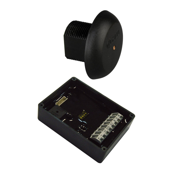
Indoor/Outdoor Proximity Card Readers - Wiegand
Lecteurs Proximité intérieur/extérieur - Wiegand
Range: Integrated access control /
Group Products
Gamme: Contrôle d'Accès intégré
MANUEL D'INSTALLATION
ENGLISH
EN
FRANCAIS
FR
INSTALLATION MANUAL
Advertisement

Related Manuals for CDVI DGLPTWLC


Summary of Contents for CDVI DGLPTWLC
- Page 1 ENGLISH FRANCAIS DGLPTWLC Indoor/Outdoor Proximity Card Readers - Wiegand Lecteurs Proximité intérieur/extérieur - Wiegand Range: Integrated access control / Gamme: Contrôle d’Accès intégré INSTALLATION MANUAL MANUEL D’INSTALLATION Group Products...
-
Page 2: General Information
INSTALLATION MANUAL DGLPTWLC Indoor/Outdoor Proximity Card readers - Wiegand 1] GENERAL INFORMATION Wiegand 26, 30 and 44 bits. Audible and visual feedback Direct connection to the controller through the door controller (INTBUSW). Flush mount. Polycarbonate. Sealed (resin moulded). Connection by 4 pair 6/10th cable Input voltage : 12 V AC/DC. WEEE & RoHS Consumption : 100 mA. CE Certifi cation IP64 Conforms to European directive R&TTE 99/5/CE and... - Page 3 INSTALLATION MANUAL DGLPTWLC Indoor/Outdoor Proximity Card readers - Wiegand 4] CONNECTIONS: DIRECT CONNECTION TO A CONTROLLER DIPSWITCH 1 & 2 POSITIONNING DIPSWITCH 3 POSITIONNING The buzzer and the LED’s can be controlled by the reader or by an external device. OFF/OFF OFF/ON 26 bits 44 bits Centaur CDVI Mode Mode ON/ON...
- Page 4 INSTALLATION MANUAL DGLPTWLC Indoor/Outdoor Proximity Card readers - Wiegand 5] CONNECTIONS: CONNECTION TO THE DOOR CONTROLLER (INTBUSW) DIPSWITCH 1 & 2 DIPSWITCH 3 POSITIONNING POSITIONNING The buzzer and the LED’s can be controlled by the reader OFF/ON or by an external device. 44 bits CDVI Mode The controller or the audio entry system can manage the LED and the buzzer to program other operations.
- Page 5 INSTALLATION MANUAL DGLPTWLC Indoor/Outdoor Proximity Card readers - Wiegand INTBUSW (Door controller) DIPSWITCH 4 Terminal block : Motherboard POSITIONNING Input voltage - Pulls up 5V Input voltage + Open collector outputs: Data O Clock Data 1 Pull up 5V Terminal block : Motherboard N/C contact eletromagnetic lock (+) Select the output voltage. Common contact power supply (+) N/O contact electric release N /C contact alarm Common N/O contact alarm + ~ - Input voltage DC or AC, 12V or 24V...
- Page 6 INSTALLATION MANUAL DGLPTWLC Indoor/Outdoor Proximity Card readers - Wiegand 6] OUTPUT FORMATS 26, 30 AND 44 BITS WIEGAND Chronograms 0 logic 1 logic \DATA1 \CLOCK \DATA0 50 µs 50 µs Open collector output with internal pulls up 1K at +5V or +12V according the ST4 position. 26-bit Wiegand Output ST5 jumper on 1.
- Page 7 INSTALLATION MANUAL DGLPTWLC Indoor/Outdoor Proximity Card readers - Wiegand Format Wiegand 30 bits ST5 jumper on 2. Signals output in open collectors with pull up in 30-bit hexadecimal format. The output format from the proximity reader is 30-bit wiegand (Signal: DATA1, DATA0 and CLOCK) and is structured as follow: 1 - First parity : 1 bit – even parity for the fi rst 14-bit Code : A code is formed from 7 half byte. Each byte is transferred from bit 7 to bit 0. 2 - Second parity: 1 bit – odd parity for the last 14-bit Bit 1 Bit 2 à bit 29 Bit 30 Even Parity from bit 2 to bit 15 Data (28-bit) Odd Parity from bit 16 to bit 29 Example A: Temic card decimal code: 689905 (in hexadecimal: A86F1).
- Page 8 INSTALLATION MANUAL DGLPTWLC Indoor/Outdoor Proximity Card readers - Wiegand 7] MOUNTING After checking that the fi tting kit is complete, you can start the fi nal installation of your reader. Fix the DGLPTWLC box inside the front panel Feed the cables through (near the head mounting the mounting screw screw hole) with double hole, and then into sided the mounting nut. adhesive tape. Connect the cable Fix the nut to the head to the box and make stud to complete the the connections to the installation. controller or the panel. 8] NOTES cdvi.com cdvigroup.com...
- Page 9 INSTALLATION MANUAL DGLPTWLC Indoor/Outdoor Proximity Card readers - Wiegand cdvi.com cdvigroup.com...
- Page 10 MANUEL D’INSTALLATION DGLPTWLC Lecteurs Proximité encastrable Wiegand - 125 Khz 1] PRESENTATION DES PRODUITS Wiegand 26, 30 ou 44 bits. Signalisation lumineuse et sonore Connexion directe sur la centrale ou par l’intermédiaire du contrôleur de porte (INTBUSW). Montage encastré. Polycarbonate. Etanche (surmoulage résine). Raccordement par câble 4 paires 6/10e. Alimentation : 12 V AC/DC. DEEE & RoHS Consommation : 100 mA.
- Page 11 MANUEL D’INSTALLATION DGLPTWLC Lecteurs Proximité encastrable Wiegand - 125 Khz 4] RACCORDEMENTS CONNEXION DIRECTE À UNE CENTRALE POSITIONNEMENT DIPSWITCH 1 & 2 POSITIONNEMENT DIPSWITCH 3 Vous avez la possibilité de gérer le buzzer et les voyants en interne ou en externe. OFF/OFF OFF/ON 26 bits 44 bits Mode Mode Centaur CDVI ON/ON ON/OFF En standard, la lecture d’un...
- Page 12 MANUEL D’INSTALLATION DGLPTWLC Lecteurs Proximité encastrable Wiegand - 125 Khz 5] RACCORDEMENTS CONNEXION AVEC CONTRÔLEUR DE PORTE (INTBUSW) POSITIONNEMENT POSITIONNEMENT DIPSWITCH 1 & 2 DIPSWITCH 3 Vous avez la possibilité de gérer le buzzer et les voyants en interne OFF/ON ou en externe. 44 bits Mode CDVI La centrale ou la platine permettent de défi...
- Page 13 MANUEL D’INSTALLATION DGLPTWLC Lecteurs Proximité encastrable Wiegand - 125 Khz INTBUSW (Contrôleur de porte) POSITIONNEMENT Bornier 5 points : Carte mère DIPSWITCH 4 Alimentation - Pulls up 12 V ou 5V Alimentation + Pour les sorties à collecteur ouvert, il Data O y a deux niveaux de sorties possibles : Clock Data 1 Pull up 5V Bornier 16 points : Carte mère Contact N.F porte Ventouse (+) Contact commun + Alimentation Permet à l’utilisateur de choisir la tension de sortie.
- Page 14 MANUEL D’INSTALLATION DGLPTWLC Lecteurs Proximité encastrable Wiegand - 125 Khz 6] FORMAT DE SORTIE WIEGAND 26, 30 ET 44 BITS Chronogrammes 0 logique 1 logique \DATA1 \CLOCK \DATA0 50 µs 50 µs Sorties en collecteur ouvert avec pulls up internes de 1K au +5V ou +12V selon la position de ST4 Format Wiegand 26 bits Cavalier ST5 sur 1.
- Page 15 MANUEL D’INSTALLATION DGLPTWLC Lecteurs Proximité encastrable Wiegand - 125 Khz Format Wiegand 30 bits Cavalier ST5 sur 2. Format 30 bits hexadécimal. La communication s’effectue par une liaison de type Wiegand 30 bits (Signaux : DATA1, DATA0 et CLOCK). La trame est constituée d’une totalité de 30 bits et se décompose comme suit : 1 - 1ère parité : 1 bit – parité paire des 14 premiers bits Code du badge : 7 quartets représentant le code du badge Chaque mot est transmis bit de poids fort en premier. 2 - 2ème parité: 1 bit – parité impaire des 12 derniers bits Bit 1 Bit 2 à bit 29 Bit 30 Parité paire sur bit 2 à bit 15 Donnée (28 bits) Parité impaire sur bit 16 à bit 29 Exemple A : pour une carte ayant le code décimal : 689905 (en hexadécimal : A86F1).
-
Page 16: Montage
MANUEL D’INSTALLATION DGLPTWLC Lecteurs Proximité encastrable Wiegand - 125 Khz 7] MONTAGE Après avoir vérifi é que le kit de montage est complet, vous allez pouvoir procéder à l’installation fi nale de votre lecteur. Réunissez le matériel approprié (Perceuse, tournevis, mètre,...) et suivez les recommandations de montage qui correspondent au lecteur que vous allez installer. Fixez le boîtier du DGLP- TWLC à l’intérieur de la fa- Passez les câbles dans le çade (à proximité du trou trou de fi xation, puis dans de fi xation de la tête) avec l’écrou de fi xation. - Page 17 MANUEL D’INSTALLATION DGLPTWLC Lecteurs Proximité encastrable Wiegand - 125 Khz cdvi.com cdvigroup.com...
- Page 18 MANUEL D’INSTALLATION DGLPTWLC Lecteurs Proximité encastrable Wiegand - 125 Khz cdvi.com cdvigroup.com...
- Page 19 MANUEL D’INSTALLATION DGLPTWLC Lecteurs Proximité encastrable Wiegand - 125 Khz cdvi.com cdvigroup.com...
- Page 20 Reference : G0301FR0318V03 Extranet : EXE-CDVI_IM DGLPTWLC CMYK A5 EN-FR 03 Manufacturing Access Control since 1985 CDVI Group CDVI CDVI DIGIT FRANCE TAIWAN ITALIA FRANCE (Headquarters/Siège social) Phone: +33 (0)1 48 91 01 02 Phone: +886 (0)42471 2188 Phone: +39 0331 97 38 08 Phone: +33 (0)1 41 71 06 85 Fax: +33 (0)1 48 91 21 21 Fax: +886 (0)42471 2131 Fax: +39 0331 97 39 70 Fax: +33 (0)1 41 71 06 86 CDVI CDVI CDVI FRANCE SWITZERLAND MAROC Phone: +33 (0)1 48 91 01 02 Phone: +41 (0)21 882 18 41 Phone: +212 (0)5 22 48 09 40 Fax: +33 (0)1 48 91 21 21 Fax: +41 (0)21 882 18 42 Fax: +212 (0)5 22 48 34 69...
Need help?
Do you have a question about the DGLPTWLC and is the answer not in the manual?
Questions and answers