
Related Manuals for MEGASTEK GVT800


Summary of Contents for MEGASTEK GVT800
- Page 1 Version Number Modified by Change Content Type Date V1.0 create 2014.06.23 GPS Multi-function Tracker User Manual Multi-function Vehicle Positioning Tracker _______________________________________ User manual...
-
Page 2: Table Of Contents
CONTENTS 1. PRODUCTS OVERVIEW················································································ 2 2. SAFETY INSTRUCTION················································································ 3 3. SPECIFICATION AND PARAMETER ······························································ 3 4. GETTING STARTED ····················································································· 4 4.1. H ······································································· 4 ARDWARE AND ACCESSORIES 4.2. V ························································································· 5 IEW AND PORT 4.3. ································································································ 5 FIRST USE PARAMETER SETTING BY SMS ································································· 7 ···············································································... -
Page 3: Products Overview
1. Products overview Thanks for purchasing our products! Tracker is a GPS/ GPRS based tracking device designed for heavy motorbike, intercity bus, school bus and fleet management. It has built-in terminals of GPS module and GSM communication module, which are used for getting the location data and send it to authorized phone number via SMS, and tracking through free maps Google Earth or Google Map;... -
Page 4: Safety Instruction
2. Safety instruction Read these simple guidelines. Not following them may damage the tracker or not perform proper function of application. Correct Connection When connect to other devices, please read its manual carefully Chosen Accessories Use our accessories, battery and external module to avoid damage to our device Installation in a Hidden Place In order to avoid damage by external force... -
Page 5: Getting Started
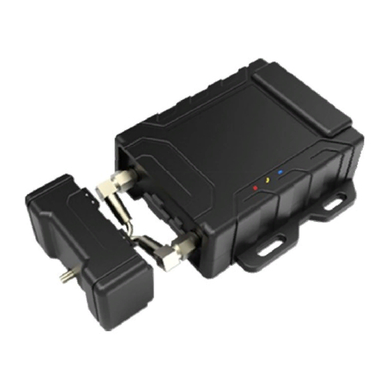
4. Getting Started This section will describe how to set the tracker. 4.1. Hardware and accessories Standard accessories: Terminal GSM antenna GPS antenna (Battery included) I/O connecting wires USB cable Optional accessories: Navigation LCD panel (PND) Navigation LCD panel (PND) Two-ways temperature sensor Camera (At most support three-ways) -
Page 6: View And Port
4.2. View and port antenna port GSM antenna port Power switch SIM card slot Micro USB port Camera 2 Camera 3 RS485(RFID) Speaker port Camera 1 I/O port Temperate sensor Two-way communication port 4.3. First use Please read this manual before using tracker and check if all parts are included in the packaging box. - Page 7 - Our device only supports micro SIM card,if it is large,please go to the local operator and cut it become the micro SIM card(do not cut to the nano SIM card) - Check the SIM card has not run out of credit money (please test the SIM card in a phone to make sure it can send and receive SMS) - Make sure that lock code of the SIM card is turned off - If you need the function of sending an SMS location report to the authorized phone number...
-
Page 8: Parameter Setting By Sms
4.4 LED indication – Power indication Always On Power charging Always OFF Power charging completed or no power Blue – GSM indication 0.3S On and 0.3S Off GSM module is initializing or calling in Always On GSM network is not registered 1S On and 3S Off GSM network is registered GSM network is registered network and GPRS... -
Page 9: Authorized Number
Authorized number SMS Command: $SMS,000000;W010,NO., Phone Number,ABCDEFGHIJKLMNOP;! Describe: set the authorized phone numbers to receive SMS alarms Explain: NO.: serial number, must be 1 or 2 or 3 Phone Number: authorized phone numbers, Max. 16 digits A SOS B IN1 C IN2 D IN3(ACC)... -
Page 10: Sos Emergency Calling
SOS emergency calling SMS command: $SMS,000000;W011, Num;! Describe: if press SOS button for 3 seconds,the tracker will call the SOS phone number Explain: Num: phone number(Max. 16 digitals ) For example: $SMS,000000;W011, 13500000000;! Set the SOS number is 13500000000 Tracking by GPRS SMS Command: $SMS,000000;W002,APN,Username,Password;W003,IP,Port;W004,ID;W005,X;W009,Y;! Description: enable GPRS tracking function. -
Page 11: Set The Time Zone
lng: Longitude, formats is ddd.dddddd, the unit is degree, if it is east longitude, minus is needed. Otherwise, omit it radius: Max. 99999.00, the unit is Km Based on preset longitude and latitude as the center of the circle, and the preset radius, a circle is defined. -
Page 12: Fuel Detector
5.10 Fuel detector AIN1/AIN2 Analog input ( AIN1) used for oil detection, range 0-3V. If there is other sensor you want to use, please make sure its voltage is suitable. Oil value is the one with highest precision, Max. .The remaining-oil-percent will be sent to the server via GPRS. The remaining-oil-percent = (AIN1/4096)*100% AIN1 value is the data to be uploaded to server by GPRS. -
Page 13: Output Application
5.12 Output application +12V DC White Relay Relay Green OUT1/OUT3 Yellow Power for ignition Battery Engine ignition loop Trackers default output OUT1/OUT3 are closed, in this case P1 and p2 are connected inside the relay: when the output is open, relay is disconnected, so we can control engine’s ignition loop. -
Page 14: Install The Device
7. Install the device 7.1. Install I/O wire I/O port Identifying Function 1 VCC DC IN Input voltage: 9 ~ 33V/1.5A 2 GND black Ground 3 SOS orange SOS emergency button 4 GND black Ground 5 IN1 brown Digital input 1(positive triggered) 6 IN2... -
Page 15: Install Lcd
7.2. Install Navigation LCD Panel (PND) LCD uses resistive screen, it supports road navigation, making a phone call, send and receive SMS, and send target location remotely, etc. (Please connected the external power when you use it). DC IN is 5V when tracker connect to the external power source Dangling Green RS232 RX... -
Page 16: Install Camera
7.4. Install camera Tracker supports three ways photographing and auto-light compensation at night. Its working voltage is 5V. Attention: if you want to take a photograph, please make sure the tracker connected the external power. Standard configuration is three ways RS232 connected camera, RS232’s port also can be customized to connect other equipments. -
Page 17: Two-Way Communication
7.6. Two-way communication The two-way communication function can only be enabled when use the headset with microphone for Apple, Samsung, MINU, Huawei etc. 7.7. Voice broadcast Tracker supports TTL voice broadcast, but this function must be customized, our standard configuration is not including this. -
Page 18: Problems And Solutions
8. Problems and solutions Problem:Tracker can not turn power switch on Possible cause resolution Low battery Please connect external power Problem: The tracker do not reply the SMS Possible cause resolution The GSM antenna conjunction Please reconnect the GSM antenna isn't connected firmly The GSM antenna conjunction is Make sure the GSM antenna and the GSM connecting base are connected...
Need help?
Do you have a question about the GVT800 and is the answer not in the manual?
Questions and answers