
Subscribe to Our Youtube Channel
Related Manuals for WABCO iABS 2S/1M Standard


Summary of Contents for WABCO iABS 2S/1M Standard
- Page 1 iABS™ TRAILER ABS SYSTEM WITH PLC AND CAN 2S/1M, 2S/2M, 4S/2M AND 4S/3M STANDARD/PREMIUM MAINTENANCE MANUAL MM19001...
- Page 2 Vehicle Electrical Grounding Guidelines ....................7 Introduction ..............................9 Identifying iABS ............................9 iABS Trailer ABS Parts .......................... 10 What Is WABCO’s iABS Trailer ABS? ....................10 System Confi guration ..........................10 How Trailer ABS Works ......................... 11 System Components ..........................11 ABS Questions and Answers ........................
- Page 3 MM19001 (en) subject to change without notice or liability. WABCO reserves the right to revise the information presented or to discontinue the production of parts described at any time.
- Page 4 How to Obtain Additional Maintenance, Service and Product Information If you have any questions about the material covered in this publication, or for more information about the WABCO product line, please contact WABCO Customer Care Center at 855-228-3203, by email at wnacustomercare@wabco-auto.com, or visit our website: www.wabco-na.com.
- Page 5 How to Obtain Additional Maintenance, Service and Product Information If you have any questions about the material covered in this publication, or for more information about the WABCO product line, please contact WABCO Customer Care Center at 855-228-3203, by email at wnacustomercare@wabco-auto.com, or visit our website: www.wabco-na.com.
- Page 6 Refer to the equipment manufacturer‘s recommended instructions for correct procedures. This manual contains maintenance procedures for WABCO’s iABS™ Trailer ABS system with PLC and CAN. Before you begin procedures: 1. Read and understand all instructions and procedures before you begin to service components.
- Page 7 If a common chassis ground point is not present, WABCO requires adding one. Do not add more than one common chassis ground point (connecting the J560 ground pin to the chassis) to avoid potential ground shifts within the vehicle electrical system.
- Page 8 Safety Information Additionally, all standard trailer components, such as axles, should also be electrically connected to the common chassis ground. If the axles are not correctly grounded to the chassis, a ground strap electrically connecting the axle to the chassis must be added to ensure adequate protection from unwanted electrical noise.
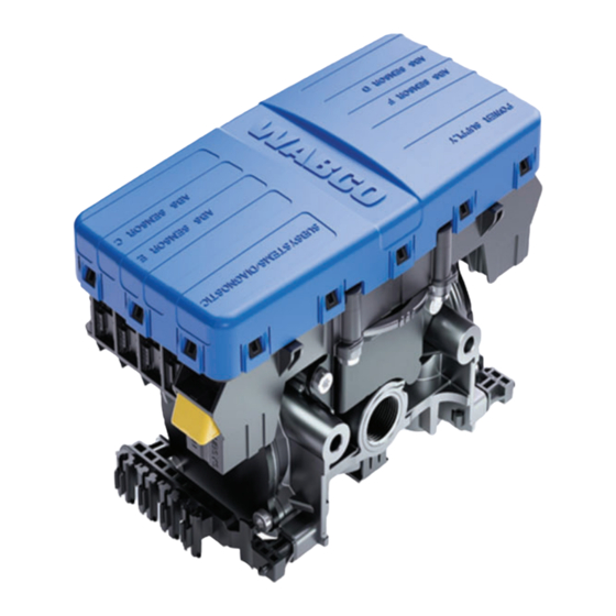
- Page 9 Introduction 3 Introduction This manual contains service and diagnostic information for WABCO iABS Trailer ABS system with Power Line Carrier (PLC) and CAN capability. 3.1 Identifying iABS To identify the iABS system, check the identifi cation tag on the Electronic Control Unit (ECU). Figure 3.1.
- Page 10 WABCO Customer Care Center at 855-228-3203. 3.3 What Is WABCO’s iABS Trailer ABS? WABCO’s iABS Trailer ABS is an electronic, self-monitoring system that works with standard air brakes. In addition, iABS includes Power Line Carrier (PLC) capability and CAN capability. PLC information is included in the ABS Q &...
- Page 11 Introduction 3.5 How Trailer ABS Works WABCO ABS is an electronic system that monitors and controls wheel speed during braking. The system works with standard air brake systems. ABS monitors wheel speeds at all times and controls braking during wheel lock situations. The system improves vehicle stability and control by reducing wheel lock during braking.
- Page 12 Introduction 3.6.3 Sensor with Molded Socket (Figure 3.5) Measures the speed of a tooth wheel rotating with the vehicle wheel. Produces an output voltage proportional to wheel speed. 3.6.4 Sensor Clip (Figure 3.6) Holds the wheel speed sensor in close proximity to the tooth wheel. 3.6.5 Tooth Wheel (Figure 3.7) ...
- Page 13 Label is self-adhesive and is mounted on the trailer near the ABS indicator lamp. If there is no warning label on your trailer, let your supervisor know. Labels are available from WABCO. Ask for Part Number TP95172. 3.6.8 TOOLBOX PLUS™ Software (Figure 3.9) TOOLBOX PLUS™...
- Page 14 Currently replaced by the heavy duty trailer diagnostic adapter. Fig. 3.10 4017175a Available from Noregon, not provided by WABCO. 3.6.10 Noregon Heavy Duty Trailer Diagnostic Adapter (Figure 3.11) Simulates the trailer ABS lamp, ensuring that the tractor is capable of “lighting the light.”...
- Page 15 ABS Questions and Answers 4 ABS Questions and Answers This section contains ABS questions and answers. 4.1 The ECU How do you activate the ECU? In a constant-powered system, the ECU activates and then begins a self-diagnostic check of the system when you turn the ignition ON.
- Page 16 If there is no Blink Code 17, the ECU is functioning correctly and does not need to be replaced; however, there could be a problem in the trailer’s wiring harness. Check the wiring system and make the necessary repairs. If the problem persists, contact the WABCO Customer Care Center at 855-228-3203. 4.3 ABS Indicator Lamps When replacing the bulb, to ensure correct lamp operation use an incandescent type DOT- approved lamp, or a LED with integral load resistor.
- Page 17 ABS Questions and Answers Most trailers manufactured prior to February 1998 require that the brakes be applied to operate the ABS indicator lamp. If the indicator lamp stays on when the brakes are applied to a moving vehicle, service the ABS system.
- Page 18 ABS Questions and Answers TABLE A: CONSTANT POWER System is Ignition Powered Fault in Brakes Ignition Vehicle Speed Indicator Lamps (Trailer and Dash) System Released N.A. N.A. Less than 4 mph ON for 3 seconds, then go OFF. Greater than 4 mph N.A.
- Page 19 Is an intermittent fault diffi cult to locate and repair? It can be, because you may not be able to easily fi nd the cause of the problem. WABCO recommends that you write down intermittent faults to help you isolate a fault that recurs over a period of time.
- Page 20 System Confi gurations 5 System Confi gurations 5.1 iABS Installation Diagrams With iABS, the 2S/1M, 2S/2M, 4S/2M and 4S/3M sensor location designations will change depending on how the ECU/dual modulator valve assembly is mounted. It may be mounted facing either the front or the rear of the trailer.
- Page 21 5.1.1 Typical iABS Trailer installation are illustrated in Figure 5.1 through 5.8: WABCO recommends placing the sensors on the axle that will provide the most braking performance. This is based on the way the suspension reacts during heavy braking applications.
- Page 22 System Confi gurations Fig. 5.2 2S/2M VALVE MOUNTED WITH CONTROL PORT FACING FRONT OF TRAILER — SIDE-TO-SIDE CONTROL FRONT OF TRAILER NOTE: Spring brake lines not shown. 2S/2M VALVE MOUNTED WITH CONTROL PORT FACING REAR OF TRAILER — SIDE-TO-SIDE CONTROL FRONT OF TRAILER NOTE: Spring brake...
- Page 23 System Confi gurations Fig. 5.3 4S/2M VALVE MOUNTED WITH CONTROL PORT FACING FRONT OF TRAILER — SIDE-TO-SIDE CONTROL FRONT OF TRAILER Typical Tandem Axle Trailer NOTE: Spring brake lines not shown. 4S/2M VALVE MOUNTED WITH CONTROL PORT FACING REAR OF TRAILER — SIDE-TO-SIDE CONTROL Typical Tandem Axle Trailer FRONT OF TRAILER...
- Page 24 System Confi gurations Fig. 5.4 4S/2M TYPICAL TRI-AXLE — VALVE MOUNTED WITH CONTROL PORT FACING FRONT OF TRAILER — SIDE-TO-SIDE CONTROL FRONT OF TRAILER NOTE: Spring brake lines not shown. 4S/2M TYPICAL TRI-AXLE — VALVE MOUNTED WITH CONTROL PORT FACING REAR OF TRAILER — SIDE-TO-SIDE CONTROL FRONT OF TRAILER NOTE: Spring brake...
- Page 25 System Confi gurations When using a 4-sensor capable ABS ECU, but only using 2 sensors, make sure the sensors used are C and D. If a sensor is plugged into the E or F port when powered up, the system will automatically confi...
- Page 26 System Confi gurations Fig. 5.6 4S/3M TYPICAL TRI-AXLE WITH FRONT LIFT — VALVE MOUNTED WITH CONTROL PORT FACING FRONT OF TRAILER FRONT OF TRAILER NOTE: Spring brake lines not shown. 4S/3M TYPICAL TRI-AXLE WITH FRONT LIFT — VALVE MOUNTED WITH CONTROL PORT FACING REAR OF TRAILER FRONT OF TRAILER SERVICE/CONTROL LINES...
- Page 27 System Confi gurations Fig. 5.7 4S/3M TYPICAL TRI-AXLE — VALVE MOUNTED WITH CONTROL PORT FACING FRONT OF TRAILER FRONT OF TRAILER NOTE: Spring brake lines not shown. SERVICE/CONTROL LINES SENSOR CABLES Typical Tandem SERVICE BRAKE Axle Trailer SUPPLY AIR 4S/3M TYPICAL TRI-AXLE — VALVE MOUNTED WITH CONTROL PORT FACING REAR OF TRAILER FRONT OF TRAILER Typical Tandem...
- Page 28 System Confi gurations Fig. 5.8 4S/3M TYPICAL FOUR AXLE PULL TRAILER — VALVE MOUNTED WITH CONTROL PORT FACING FRONT OF TRAILER FRONT OF NOTE: Spring brake TRAILER lines not shown. SERVICE/CONTROL LINES SENSOR CABLES SERVICE BRAKE SUPPLY AIR 4S/3M TYPICAL FOUR AXLE PULL TRAILER — VALVE MOUNTED WITH CONTROL PORT FACING REAR OF TRAILER FRONT OF TRAILER...
- Page 29 System Confi gurations 5.2 Power Cable Wiring Diagrams Fig. 5.9 WHITE (GROUND) BLUE (CONSTANT POWER) (STOP LAMP) GREEN AND WHITE ECU POWER CONNECTOR TRAILER ABS INDICATOR LAMP GROUND Junction box not shown. 4013987a Fig. 5.10 POWER CABLE FOR iABS P/N 449 306 XXX 0 NOT USED NOT USED NOT USED...
- Page 30 There is also a new diagnostic tool for checking PLC, the Heavy Duty Trailer Diagnostic adapter. Figure 6.1. Fig. 6.1 4017175a Available from Noregon, not provided by WABCO. 6.1 Important PLC Information for Blink Code Diagnostics Blink Code 17 indicates a PLC failure. If PLC does not seem to be operating correctly, but there is no Blink Code 17, the ECU is functioning correctly and does not need to be replaced;...
- Page 31 This screen provides icon and pull-down menu task selections. It also provides information about the current state of the WABCO iABS ECU/Valve Assembly. ECU information is read once from the ECU and does not change. Wheel speed, voltages, faults and information are read and updated continuously.
- Page 32 Diagnostics Fig. 6.3 4014081a Tire Calibration Tire calibration may be accessed from the Modify pull-down on the Main Screen. Figure 6.4. Fig. 6.4 4003664b The programmed number of millimeters for tire circumference is displayed on the Tire Calibration screen. The allowable range is dependent on the number of teeth on the tone ring. Use the tire manufacturer‘s recommended tire circumference in millimeters for this value.
- Page 33 Diagnostics Service Information Service Information may be accessed from the Modify pull-down on the Main Screen. In the Service Information fi eld, the ECU, working with a constant powered tractor, can act as a mileage counter. This fi eld can also be used to set service intervals. Figure 6.5. Fig.
- Page 34 Diagnostics Fig. 6.6 4015790a Sensor Orientation Test The Sensor Orientation Test is used to determine the correct installation, wiring and and confi rm if sensors are installed on a lift axle that the correct sensors are used. The screen display will provide the maximum tested sensor RPM for the installed sensors.
- Page 35 Diagnostics Report Information The Report Information screen allows the user to store information about a specifi c vehicle, including the Vehicle Identifi cation Number (VIN) and Employee numbers. Figure 6.8. Fig. 6.8 4012505b An example of a storable (or printable) report is displayed in Figure 6.9.
- Page 36 Diagnostics Fig. 6.9 4015791a Save and Print 1. Click on the heading Trailer ECU and click Save. A window will appear asking for the Plant Location, VIN, OEM and Employee number. Refer to Figure 6.8. 2. Provide this information and select where you would like the fi le saved and then press OK. 3.
- Page 37 Diagnostics 6.3 Initial Power-up Check Whenever the trailer is initially powered up, the ABS light should come on for three seconds and the valves should click during its self-test. If the ABS light comes on again during the same ignition cycle, it would indicate an issue.
- Page 38 Diagnostics 6.5 Blink Code Diagnostics The WABCO iABS ECU detects any electrical fault in the trailer ABS. Each of the faults has a code. When a fault occurs, the ECU stores the code for that fault in the memory. There are two kinds of faults: active and stored. Active faults are those currently existing in the system, such as a broken wire.
- Page 39 Check power supply. Perform necessary repairs. Verify correct installation. If code continues, Internal ABS Modulator Valve contact WABCO Customer Care Center at 855-228-3203 for assistance. No Speed Failure Spin tires or drive the vehicle above 4 mph. External Pressure Sensor Internal failure, contact WABCO Customer Care Center at 855-228-3203 for assistance.
- Page 40 Diagnostics 6.5.2 SID/FMI Diagnostic Codes Diagnostic Table Suspect Fault Blink Component Description Cause Repair Information Code Function and Location (FMI) Wheel Air Gap Sensor air gap is - Adjust wheel sensor to touch Speed too large; sensor tone ring. Sensor C output voltage is - Check condition of ABS too low but is high...
- Page 41 Diagnostics Suspect Fault Blink Component Description Cause Repair Information Code Function and Location (FMI) Wheel Open Circuit An open circuit - Check sensor, sensor cable Speed has been detected, and connectors to verify no Sensor C i.e. ECU detects a loose or damaged connection.
- Page 42 Diagnostics Suspect Fault Blink Component Description Cause Repair Information Code Function and Location (FMI) Wheel Tone Ring Wheel speed - Check for damaged or Speed Damaged signal drops out missing teeth on tone ring. Sensor C periodically at - Verify tone ring is speeds higher than not corroded or with 6 mph.
- Page 43 Diagnostics Suspect Fault Blink Component Description Cause Repair Information Code Function and Location (FMI) Wheel Speed Jump Wheel speed - Adjust wheel speed sensor Speed Upwards or difference. until it touches the tone ring. Sensor C Downwards - Check for loose wheel bearings or excessive hub runout.
- Page 44 Diagnostics Suspect Fault Blink Component Description Cause Repair Information Code Function and Location (FMI) Wheel A non-plausible - Check sensor wiring and speed Intelligent sensor frequency connectors for intermittent sensor c Device or has been contact. Component measured. - Check if brake at this location is operating correctly, i.e., potentially dragging.
- Page 45 Diagnostics Suspect Fault Blink Component Description Cause Repair Information Code Function and Location (FMI) Wheel Air Gap Sensor air gap is - Adjust wheel sensor to touch Speed too large; sensor tone ring. Sensor D output voltage is - Check condition of ABS too low but is high sensor head.
- Page 46 Diagnostics Suspect Fault Blink Component Description Cause Repair Information Code Function and Location (FMI) Wheel Shorted to Continuity between - Check sensor, sensor cable Speed Ground the sensor and connectors to verify no Sensor D connection and loose or damaged connection. ground (short - Verify 900-2000 ohms circuit) is detected.
- Page 47 Diagnostics Suspect Fault Blink Component Description Cause Repair Information Code Function and Location (FMI) Wheel Short Circuit Continuity - Check for damaged or Speed interruption missing teeth on tone ring. Sensor D between the sensor - Verify tone ring is connections (short not corroded or with circuit) has been...
- Page 48 Diagnostics Suspect Fault Blink Component Description Cause Repair Information Code Function and Location (FMI) Wheel No Speed A temporary loss - Adjust wheel speed sensor Speed of the ABS wheel until it touches the tone ring. Sensor D speed signal has - Check for loose wheel been detected.
- Page 49 Diagnostics Suspect Fault Blink Component Description Cause Repair Information Code Function and Location (FMI) Wheel Abnormal Brake drag or - Check for loose wheel Speed Speed chatter has been bearings or excessive hub Sensor D (Chatter) detected. Abnormal runout. vibrations detected - Check sensor wiring and which affect sensor connectors for intermittent...
- Page 50 Diagnostics Suspect Fault Blink Component Description Cause Repair Information Code Function and Location (FMI) Wheel Wheel Tone ring signal - Check for loose wheel Speed Speed irregular. bearings or excessive hub Sensor D Oscillating runout. - Check sensor wiring and connectors for intermittent contact.
- Page 51 Diagnostics Suspect Fault Blink Component Description Cause Repair Information Code Function and Location (FMI) Wheel Air Gap Sensor air gap is - Adjust wheel sensor to touch Speed too large; sensor tone ring. Sensor E output voltage is - Check condition of ABS too low but is high sensor head.
- Page 52 Diagnostics Suspect Fault Blink Component Description Cause Repair Information Code Function and Location (FMI) Wheel Shorted to Continuity between - Check sensor, sensor cable Speed Ground the sensor and connectors to verify no Sensor E connection and loose or damaged connection. ground (short - Verify 900-2000 ohms circuit) is detected.
- Page 53 Diagnostics Suspect Fault Blink Component Description Cause Repair Information Code Function and Location (FMI) Wheel Short Circuit Continuity - Check for damaged or Speed interruption missing teeth on tone ring. Sensor E between the sensor - Verify tone ring is connections (short not corroded or with circuit) has been...
- Page 54 Diagnostics Suspect Fault Blink Component Description Cause Repair Information Code Function and Location (FMI) Wheel No Speed A temporary loss - Adjust wheel speed sensor Speed of the ABS wheel until it touches the tone ring. Sensor E speed signal has - Check for loose wheel been detected.
- Page 55 Diagnostics Suspect Fault Blink Component Description Cause Repair Information Code Function and Location (FMI) Wheel Abnormal Brake drag or - Check for loose wheel Speed Speed chatter has been bearings or excessive hub Sensor E (Chatter) detected. Abnormal runout. vibrations detected - Check sensor wiring and which affect sensor connectors for intermittent...
- Page 56 BU2 sensor port. - If a sensor has been installed on BU2 sensor port at some point and is no longer present, reconfi gure the ECU using WABCO TOOLBOX PLUS™ diagnostic software. Wheel Data Valid, Implausible high - Check for possible EM...
- Page 57 Diagnostics Suspect Fault Blink Component Description Cause Repair Information Code Function and Location (FMI) Wheel Air Gap Sensor air gap is - Adjust wheel sensor to touch Speed too large; sensor tone ring. Sensor F output voltage is - Check condition of ABS too low but is high sensor head.
- Page 58 Diagnostics Suspect Fault Blink Component Description Cause Repair Information Code Function and Location (FMI) Wheel Shorted to Continuity between - Check sensor, sensor cable Speed Ground the sensor and connectors to verify no Sensor F connection and loose or damaged connection. ground (short - Verify 900-2000 ohms circuit) is detected.
- Page 59 Diagnostics Suspect Fault Blink Component Description Cause Repair Information Code Function and Location (FMI) Wheel Short Circuit Continuity - Check for damaged or Speed interruption missing teeth on tone ring. Sensor F between the sensor - Verify tone ring is connections (short not corroded or with circuit) has been...
- Page 60 Diagnostics Suspect Fault Blink Component Description Cause Repair Information Code Function and Location (FMI) Wheel No Speed A temporary loss - Adjust wheel speed sensor Speed of the ABS wheel until it touches the tone ring. Sensor F speed signal has - Check for loose wheel been detected.
- Page 61 Diagnostics Suspect Fault Blink Component Description Cause Repair Information Code Function and Location (FMI) Wheel Abnormal Brake drag or - Check for loose wheel Speed Speed chatter has been bearings or excessive hub Sensor F (Chatter) detected. Abnormal runout. vibrations detected - Check sensor wiring and which affect sensor connectors for intermittent...
- Page 62 - Verify no signs of moisture or corrosion at E or F sensor port. - If a sensor has been installed on the E or F sensor port at some point and is no longer present, reconfi gure the ECU using WABCO TOOLBOX PLUS™ diagnostic software.
- Page 63 2S/2M or 4S/2M system depending on how many sensors are used through the WABCO TOOLBOX PLUS™ Software. - If equipped with an external modulator, verify resistance from the exhaust and inlet...
- Page 64 2S/2M or 4S/2M system depending on how many sensors are used through the WABCO TOOLBOX PLUS™ Software. - If equipped with an external modulator verify resistance from the exhaust and inlet...
- Page 65 2S/2M or 4S/2M system depending on how many sensors are used through the WABCO TOOLBOX PLUS™ Software. - If equipped with an external modulator verify resistance from the exhaust and inlet...
- Page 66 2S/2M or 4S/2M system depending on how many sensors are used through the WABCO TOOLBOX PLUS™ Software. - If equipped with an external modulator, verify resistance from the exhaust and inlet...
- Page 67 2S/2M or 4S/2M system depending on how many sensors are used through the WABCO TOOLBOX PLUS™ Software. - If equipped with an external modulator, verify resistance from the exhaust and inlet...
- Page 68 Diagnostics Suspect Fault Blink Component Description Cause Repair Information Code Function and Location (FMI) Internal H1 Trailer ECU has detected - Verify the ABS ECU power Modulator Modulator/ an over voltage/ connector is seated properly Valve Solenoid short to supply and has no signs of moisture Valve Control voltage condition...
- Page 69 ECU. the ABS relay valve and the ABS relay valve itself. If there are no abnormalities, contact WABCO Support. Brake Pad Brake Brake Pad The wear sensor - The measured values from...
- Page 70 Diagnostics Suspect Fault Blink Component Description Cause Repair Information Code Function and Location (FMI) Axle Axle Load The cable to the - Check the cable between Component Load Sensor external axle load modulator and the connected External sensor (axle c-d) is component.
- Page 71 Diagnostics Suspect Fault Blink Component Description Cause Repair Information Code Function and Location (FMI) External External Supply pressure on - The supply pressure fell Component Supply Supply the trailer is below below 4.5 bar whilst the Pres- Pressure 4.5 bar. vehicle was being driven.
- Page 72 Diagnostics Suspect Fault Blink Component Description Cause Repair Information Code Function and Location (FMI) External External Overload was - Check the cable between Component Supply Supply detected at external modulator and the connected Pres- Pressure supply pressure component. sure Sensor - sensor.
- Page 73 Diagnostics Suspect Fault Blink Component Description Cause Repair Information Code Function and Location (FMI) Power Power A deep - The power supply to the Supply Supply - undervoltage has trailer modulator is insuffi cient Deep Under- occurred. and/or lies below the normal voltage voltage range.
- Page 74 - Define the modulator Error Setting - setting is incorrect. parameters again. If failure is External A GIO function is still present, contact WABCO Pin Not parameterized to Customer Care Center at Compatible an improper pin. 855-228-3203 for assistance. Internal ECU...
- Page 75 Trap Internal checksum - Switch ignition off for at least Error Handler - error. 5s. If the fault exists then, Trap Set contact WABCO Customer Care Center at 855-228-3203 for assistance. 1264 Tire Inflation Tire Tire Inflation Possible break - Check whether load is...
- Page 76 Diagnostics Suspect Fault Blink Component Description Cause Repair Information Code Function and Location (FMI) 1456 Multiple Free A short circuit to - Verify connectors are Component Confi gurable supply voltage was properly seated and have no Func- Function - detected at the signs of moisture or corrosion.
- Page 77 Diagnostics Suspect Fault Blink Component Description Cause Repair Information Code Function and Location (FMI) 1472 Multiple Free A short circuit - Verify connectors are Component Confi gurable to ground was properly seated and have no Func- Function - detected at the signs of moisture or corrosion.
- Page 78 Diagnostics Suspect Fault Blink Component Description Cause Repair Information Code Function and Location (FMI) 1473 Multiple Free Nothing is - Verify connectors are Component Confi gurable connected at properly seated and have no Func- Function - the digital output signs of moisture or corrosion. tions (DOut2) 2 of the freely...
- Page 79 Diagnostics Suspect Fault Blink Component Description Cause Repair Information Code Function and Location (FMI) 1474 Multiple Free Overload was - Verify connectors are Component Confi gurable detected at the properly seated and have no Func- Function - freely confi gurable signs of moisture or corrosion.
- Page 80 Diagnostics Suspect Fault Blink Component Description Cause Repair Information Code Function and Location (FMI) 1568 Slider Slider Status A short circuit to - Verify connectors are Component Status supply voltage was properly seated and have no Overvoltage/ detected at Slider signs of moisture or corrosion.
- Page 81 Diagnostics Suspect Fault Blink Component Description Cause Repair Information Code Function and Location (FMI) 1632 Multiple GIO_ Overload was - Verify connectors are Component Powerstage - detected at GIO1 properly seated and have no Func- (PwrStage1) pin 1. signs of moisture or corrosion. tions Current - Check for signs of damage to...
- Page 82 Diagnostics Suspect Fault Blink Component Description Cause Repair Information Code Function and Location (FMI) 1648 Multiple GIO_ A short circuit - Check whether water or Component Powerstage - to ground was moisture has entered into the Func- (PwrStage2) detected at GIO1 connector/ dummy cap and tions Under-...
- Page 83 Diagnostics Suspect Fault Blink Component Description Cause Repair Information Code Function and Location (FMI) 1648 Multiple GIO_ A component for - Check the parameter setting. Component Powerstage - which there are no - Check whether the correct Func- (PwrStage2) parameter settings cables are used.
- Page 84 Diagnostics Suspect Fault Blink Component Description Cause Repair Information Code Function and Location (FMI) 1664 Multiple GIO_ A short circuit - Check whether water or Component Powerstage - to ground was moisture has entered into the Func- (PwrStage3) detected at GIO2 connector/ dummy cap and tions Under-...
- Page 85 Diagnostics Suspect Fault Blink Component Description Cause Repair Information Code Function and Location (FMI) 1664 Multiple GIO_ Overload was - Check whether water or Component Powerstage - detected at GIO2 moisture has entered into the Func- (PwrStage3) pin 1. connector/ dummy cap and tions Current check the seals for proper fi...
- Page 86 Diagnostics Suspect Fault Blink Component Description Cause Repair Information Code Function and Location (FMI) 1680 Multiple GIO_ A short circuit to - Check whether water or Component Powerstage - supply voltage was moisture has entered into the Func- (PwrStage4) detected at GIO2 connector / dummy cap and tions Voltage...
- Page 87 Diagnostics Suspect Fault Blink Component Description Cause Repair Information Code Function and Location (FMI) 1680 Multiple GIO_ Cable break - Check whether water or Component Powerstage - detected to load at moisture has entered into the Func- (PwrStage4) GIO2 pin 4. connector/ dummy cap and tions Supply Cable...
- Page 88 Diagnostics Suspect Fault Blink Component Description Cause Repair Information Code Function and Location (FMI) 1760 Diagnostic Subsystem A short circuit to - Check the cable between Connector Power supply voltage modulator and the connected Terminal - was detected at component. (Cl30) Subsystems pin 1 - Check for tight seat of the...
- Page 89 Diagnostics Suspect Fault Blink Component Description Cause Repair Information Code Function and Location (FMI) 1761 Diagnostic Subsystem A short circuit to - Check the cable between Connector Power supply voltage modulator and the connected Terminal - was detected at component. (Cl15) Subsystems pin 5 - Check for tight seat of the...
- Page 90 Diagnostics Suspect Fault Blink Component Description Cause Repair Information Code Function and Location (FMI) 1792 Lift Axle Forced The cable to the - Check the cable between Component Lowering button for the modulator and the connected Switch - forced lowering of component.
- Page 91 Diagnostics Suspect Fault Blink Component Description Cause Repair Information Code Function and Location (FMI) 1809 Subsystem Smart Smartboard - The cable to the - Check the cable between Connection Board Under- SmartBoard has modulator and the connected voltage/ a short circuit to component.
- Page 92 Diagnostics Suspect Fault Blink Component Description Cause Repair Information Code Function and Location (FMI) 1824 Subsystem Diagnostic Overload was - Check the cable between Connection Supply - detected at modulator and the connected Current diagnostic power component. Too High supply. - Check for tight seat of the or Circuit connectors.
- Page 93 Diagnostics Suspect Fault Blink Component Description Cause Repair Information Code Function and Location (FMI) 1841 Subsystem Telematics - The cable to the - Check the cable between Connection Under- telematics system modulator and the connected voltage/ has a short circuit component.
- Page 94 Diagnostics Suspect Fault Blink Component Description Cause Repair Information Code Function and Location (FMI) 1857 IVTM IVTM - The cable to the - Check the cable between Component Under- IVTM has a short modulator and the connected voltage/ circuit to ground. component.
- Page 95 Diagnostics Suspect Fault Blink Component Description Cause Repair Information Code Function and Location (FMI) 2016 Multiple Output The cable to the - Check the cable between Component Speed component on the modulator and the connected Func- Signal - speed output is component.
- Page 96 Diagnostics Suspect Fault Blink Component Description Cause Repair Information Code Function and Location (FMI) 2080 Multiple Permanent The cable to the - Check the cable between Component Power 1 - component on the modulator and the connected Func- Under- permanent power component.
- Page 97 Diagnostics Suspect Fault Blink Component Description Cause Repair Information Code Function and Location (FMI) 2096 Multiple Permanent The cable to the - Check the cable between Component Power 2 - component on the modulator and the connected Func- Overvoltage/ permanent power component.
- Page 98 Diagnostics Suspect Fault Blink Component Description Cause Repair Information Code Function and Location (FMI) 2096 Multiple Permanent Overload was - Check the cable between Component Power 2 detected at the modulator and the connected Func- - Current permanent power component. tions Too High output 2.
- Page 99 Diagnostics Suspect Fault Blink Component Description Cause Repair Information Code Function and Location (FMI) 2128 Multiple ABS Active The cable to the - Check the cable between Component Signal - component on the modulator and the connected Func- Supply Cable output "ABS active"...
- Page 100 Diagnostics Suspect Fault Blink Component Description Cause Repair Information Code Function and Location (FMI) 2192 Inte- Speed The cable to the - Check the cable between Component grated Switch 2 - component on the modulator and the connected Speed Under- speed switch 2 component.
- Page 101 Diagnostics Suspect Fault Blink Component Description Cause Repair Information Code Function and Location (FMI) 2208 Inte- Speed The cable to the - Check the cable between Component grated Switch 1 - component on the modulator and the connected Speed Overvoltage/ speed switch 1 component.
- Page 102 Diagnostics Suspect Fault Blink Component Description Cause Repair Information Code Function and Location (FMI) 2208 Inte- Speed Overload was - Check the cable between Component grated Switch 1 - detected at the modulator and the connected Speed Current speed switch 1 component.
- Page 103 Diagnostics Suspect Fault Blink Component Description Cause Repair Information Code Function and Location (FMI) 2256 Lift Axle Lifting Axle The cable to the - Check the cable between Component Valve 2 - lifting axle valve 2 modulator and the connected Supply Cable is not connected or component.
- Page 104 Diagnostics Suspect Fault Blink Component Description Cause Repair Information Code Function and Location (FMI) 2272 Lift Axle Lifting Axle The cable to the - Check the cable between Component Valve 1 - lifting axle valve 1 modulator and the connected Under- has a short circuit component.
- Page 105 Diagnostics Suspect Fault Blink Component Description Cause Repair Information Code Function and Location (FMI) 2352 Lift Axle Lifting Axle The cable to lifting - Check the cable between Component Status axle status lamp modulator and the connected Lamp - has a short circuit component.
- Page 106 Diagnostics Suspect Fault Blink Component Description Cause Repair Information Code Function and Location (FMI) 2352 Lift Axle Lifting Axle Overload was - Check the cable between Component Status detected at the modulator and the connected Lamp - lifting axle status component.
- Page 107 Diagnostics Suspect Fault Blink Component Description Cause Repair Information Code Function and Location (FMI) 2672 Steering Steering The cable for the - Check the cable between Component Axle Axle Lock steering axle lock modulator and the connected Lock Valve - has a short circuit component Under-...
- Page 108 Diagnostics Suspect Fault Blink Component Description Cause Repair Information Code Function and Location (FMI) 2688 Steering Steering The cable for the - Check the cable between Component Axle Axle Lock steering axle lock modulator and the connected Lock Switch - switch has a short component.
- Page 109 - Check whether the cable is frayed. - Please open the fault memory dialogue ELEX and follow the error information there. Contact WABCO customer service for further help. - If no other fault can be found, replace the connected components.
- Page 110 Connection Internal memory of memory dialogue ELEX and Failure the Electronic follow the error information Extension Module. there. - Contact WABCO customer service for further help. 2752 Subsystem ELEX ELEX - A pin is not - Possible the Electronic Connection...
- Page 111 - Check whether the cable is frayed. - Please open the fault memory dialogue ELEX and follow the error information there. Contact WABCO Customer Care Center at 855-228-3203 for assistance. - If no other fault can be found, replace the connected components.
- Page 112 - Check whether the cable is frayed. - Please open the fault memory dialogue ELEX and follow the error information there. Contact WABCO Customer Care Center at 855-228-3203 for assistance. - If no other fault can be found, replace the connected components.
- Page 113 Diagnostics Suspect Fault Blink Component Description Cause Repair Information Code Function and Location (FMI) 3393 Lift Axle Lift Axle Off The cable for the - Check the cable between Component Switch 2 - switch Lifting axle modulator and the connected Voltage 1 off or Lifting 2 off component.
- Page 114 Diagnostics Suspect Fault Blink Component Description Cause Repair Information Code Function and Location (FMI) 3712 Working Working The cable for the - Check the cable between Component Light Light - working light is not modulator and the connected Supply Cable connected or cable component.
- Page 115 Component Replacement 7 Component Replacement Hazard Alert Messages Read and observe all Warning and Caution hazard alert messages in this publication. They provide information that can help prevent serious personal injury, damage to components, or both. WARNING To prevent serious eye injury, always wear safe eye protection when you perform vehicle maintenance or service.
- Page 116 Component Replacement 7.1 Wheel Speed Sensor 7.1.1 How to Remove a Sensor 1. Follow the trailer manufacturer’s instructions to back off the slack adjuster and remove the tire, wheel and drum. 2. Hold the sensor, not the cable, and use a twisting motion to pull the sensor out of its mounting block. 3.
- Page 117 Component Replacement 4. Install the wheel hub carefully, so that the sensor pushes against the tooth wheel as you adjust the wheel bearings. After installation there should be no gap between the sensor and the tooth wheel. During normal operation a gap of 0.040-inch is allowable. If the gap is too large, this can cause the ECU to log a fault code.
- Page 118 Component Replacement 7.2.2 How to Install a Standard ABS Relay Valve DANGER You must use Schedule 80 pipe nipple (3/4-inch NPTF) to nipple-mount the ABS relay valve securely to the reinforced air tank to avoid possible serious personal injury and damage to components when tank mounting the ECU valve.
- Page 119 Component Replacement 7.3.1 How to Remove the ECU/Valve Assembly 1. Release all pressure from the air system. 2. Attach labels to identify all air lines. 3. Disconnect the air lines from the ECU/Valve Assembly. 4. Disconnect the power cable, additional relay valve cable (if used), and all sensor cables from the ECU/Valve Assembly.
- Page 120 1. Use a 3/4-inch Schedule 80 hex nipple to attach ECU/single modulator valve assembly to a reinforced air tank. Do not overtighten. WABCO does not recommend use of a vise when installing the hex nipple. Use of a vise may cause overclamping. Overclamping may damage the internal components of the ECU/ single modulator valve assembly.
- Page 121 Component Replacement 7.3.2.2 Bracket-Mounted to Cross Member of Vehicle (2S/1M Standard) 1. Install a 3/4-inch NPT fi tting in supply port (Port 1). Use a 3/4-inch pipe plug to plug unused supply port (Port 1). Use a 3/4-inch pipe plug to plug unused supply port (Port 1). Apply SAE-standard, DOT-approved sealing paste to either the fi...
- Page 122 Component Replacement 7.3.2.3 Mounted to Cross Member of Vehicle — 2S/2M, 4S/3M Standard and Premium Mounting Bracket Not Supplied 1. Install a 3/4-inch NPT fi tting in supply port. Use a 3/4-inch pipe plug to plug unused supply port (Port 1). Figure 7.9. Apply SAE-standard, DOT-approved sealing paste to either the fi...
- Page 123 Sensor Adjustment and Component Testing 8 Sensor Adjustment and Component Testing 8.1 How to Test Wheel Speed Sensors At initial installation, no gap must exist between the sensor and the tooth wheel. Otherwise the sensor may not read wheel speed, and the ABS ECU may set a fault code. After you install a hub, always check that the sensor is adjusted correctly.
- Page 124 If the resistance is greater than 8.0 ohms, clean the electrical contacts. Check the resistance again. 8.4 End of Line Testing End of line testing is required on all iABS installations. To run these tests, WABCO recommends you use TOOLBOX PLUS™ Software.
- Page 125 WABCO TOOLBOX PLUS™ Software. Refer to the MM19047 User Guide, for instructions for running TOOLBOX PLUS™ Software. The manual can be found at www.wabco-na.com in the literature section. 2. Open the i-ABS Diagnostics from the TOOLBOX PLUS™ Main Screen. Figure 8.3.
- Page 126 Sensor Adjustment and Component Testing 3. Verify power supply: Apply 12 (9.5 to 14 is acceptable) volts DC to the blue wire (constant power). Check the screen for the correct voltage it is displayed in the Primary Voltage fi eld. Figure 8.4. Fig.
- Page 127 Sensor Adjustment and Component Testing Fig. 8.6 4014083a 2. The H1 valve indicator will be selected. Click on the Activate button and listen for the valve to click, indicating a good installation. The Test Status box at the bottom of the menu will also display the status of this test.
- Page 128 Sensor Adjustment and Component Testing 4. At the Trailer Main Screen click on Component Test, then select Valves/Lamp to display the Valve Activation Screen. The H1 valve indicator will be highlighted. Figure 8.7. Selecting “All Valves” will sequence all of the valves beginning with the H1 valve. Fig.
- Page 129 Sensor Adjustment and Component Testing • If the control port faces the rear of the trailer, the slack adjusters will move in and out as the curbside portion of the dual modulator valve cycles. If this does not happen, the air lines are not correctly connected.
- Page 130 Make the necessary repairs and repeat the sensor test. If the problem persists, contact WABCO Customer Care Center at 855-228-3203. 8. Check Order fi elds to verify sensors were installed in the right location based on orientation of the valves.
- Page 131 Sensor Adjustment and Component Testing 3. Apply 12 volts DC to the ABS. 4. At the Trailer Main Menu, click on Component Test, then select Sensor Orientation Test to display the Sensor Orientation Test screen. Figure 8.10. When the Sensor Orientation Test screen fi rst appears, the Control Port Facing fi eld will display the default—Front.
- Page 132 Perform the necessary repairs and repeat the test. If the problem persists, contact the WABCO Customer Care Center at 855-228-3203. Sensor output appears in the Sensors fi eld located in the bottom right portion of the Sensor Orientation Test screen.
- Page 133 Sensor Adjustment and Component Testing 4. If the ABS lamp does not go out, there is a sensor gap problem or hardware fault. Adjust the sensor and, if necessary, perform a fault code check. 8.6 Inspect the Sensor and Air Line Installation (2S/2M Standard) 8.6.1 Sensor Installation 1.
- Page 134 Sensor Adjustment and Component Testing Fig. 8.14 CONTROL PORT DELIVERY PORTS 2.2 DELIVERY PORTS 2.1 4014011a 3. If the air lines are not correctly routed, perform the necessary repairs. 8.6.3 Inspect the Sensor and Air Line Installation (2S/2M, 4S/2M and 4S/3M Standard and Premium) 8.6.3.1 Sensor Installation 1.
- Page 135 Sensor Adjustment and Component Testing 4S/2M* • Connect curbside front sensor at C. • Connect curbside rear sensor at E. • Connect roadside front sensor at D. • Connect roadside rear sensor at F. 4S/3M*— Sensor locations vary by type of installation. Refer to the diagrams for specifi c sensor ...
- Page 136 Sensor Adjustment and Component Testing Fig. 8.16 CONTROL PORT DELIVERY PORTS 2.2 DELIVERY PORTS 2.1 4014011a 3. For 4S/3M installations: Repeat this test for the external modulator valve. The external relay valve is an axle control valve. It controls the brake chambers on one or two axles. It is important that delivery lines from Port 2 are plumbed as shown in Figure 5.6, Figure 5.7 and Figure 5.8.
- Page 137 GIO Failure Check power supply. Perform necessary repairs. Load Sensing Failure Internal failure, contact WABCO. Axle Load Failure Internal failure, contact WABCO. Brake Pad Sensor Failure Internal failure, contact WABCO. To contact WABCO, call the WABCO Customer Care Center at 855-228-3203.
- Page 138 An iABS Trailer ABS warning label is generally affi xed to the trailer near the ABS trailer indicator lamp. If this label is not on the trailer, let your supervisor know. Labels are available from WABCO. Ask for Part Number TP95172.
- Page 139 Refer to Figures 9.9, 9.10, and 9.11 in this section for the correct schematic, depending upon the override switch confi guration. For additional information, refer to TP19039, Automatic Lift Axle Installation Manual, available at www.wabco-na.com.
- Page 140 Premium ECU. This process can be found in the Automatic Lift Axle Installation Manual, TP19039. This troubleshooting section is based on the use of TOOLBOX PLUS™ Software version 13 or higher. If you have an earlier version of software, visit wabco.snapon.com to purchase and download the latest version of the software.
- Page 141 Troubleshooting Condition Action to Take Troubleshooting Detail Experienced Refer to Figure 9.5 for the connector diagram of Pressure Switch 431 700 002 0. Use regulated shop air and an ohm meter to check the functionality of the Test the pressure switch 431 switch.
- Page 142 Troubleshooting Condition Action to Take Troubleshooting Detail Experienced Ensure the trailer has blue center pin power at the J560 connector at the front of the trailer. Inspect the Verify power to the ECU. towing vehicle's power output to the J560. Ensure the J560 is wired correctly to the trailer OEM's specifi...
- Page 143 Troubleshooting Condition Action to Take Troubleshooting Detail Experienced Ensure pressure switch 431 700 002 0 is plumbed Inspect pneumatic component correctly. Refer to Figures 9.9 through 9.11 for installation. the plumbing schematics, depending on system confi guration. Ensure pressure sensor 441 044 106 0 is plumbed Inspect pneumatic component correctly.
- Page 144 Troubleshooting Condition Action to Take Troubleshooting Detail Experienced Ensure that the correct While entering the parameters to program the iABS indication lamp type is with Auto Lift Axle function, ensure that Lift Axle Status activated. Lamp is either LED or Incandescent Lamp. Using a volt/ohm meter, check for a shorted or open Check light output cable circuit on lift axle indication lamp cable 449 827 XXX 0.
- Page 145 Troubleshooting Fig. 9.1 POWER CABLE FOR iABS P/N 449 306 XXX 0 NOT USED NOT USED NOT USED NOT USED 4016467a Fig. 9.2 4017181a Fig. 9.3 4017178a...
- Page 146 Troubleshooting Fig. 9.4 LIFT AXLE CONTROL VALVE, P/N 463 084 050 0 4012470a Fig. 9.5 PRESSURE SWITCH, P/N 431 700 002 0 3/8-18 NPTF NORMALLY CLOSED 1-1/8 HEX 4012471a...
- Page 147 Troubleshooting Fig. 9.6 4017179a Fig. 9.7 4017177a Fig. 9.8 ABS LIFT AXLE “Y” CABLE, P/N 894 601 100 0 YE/GN YE/GN N.C. N.C. YE/GN N.C. 4012667a...
- Page 148 Troubleshooting Fig. 9.9 4017182a...
- Page 149 Troubleshooting Fig. 9.10 4017180a...
- Page 150 Troubleshooting Fig. 9.11 4017173a...
- Page 151 Troubleshooting Fig. 9.12 LIFT AXLE TEST RIG STANDARD MALE QUICK COUPLER FITTING PRESSURE REGULATOR WITH GAUGE PRESSURE REGULATOR WITH GAUGE FITTING (0-100 PSI) (0-100 PSI) FITTING FITTING SIMULATED SPRING BRAKE SIMULATED AIR LINE SUSPENSION LINE 1/2" HOSE 1/2" HOSE 1/2" TO 3/8" 1/2"...
- Page 152 This process can be found in the Tag Axle Installation Manual, TP19030. This troubleshooting section is based on the use of TOOLBOX PLUS™ Software version 13 or higher. If you have an earlier version of software, visit wabco.snapon.com to purchase and download the latest version of the software.
- Page 153 Troubleshooting Condition Action to Take Troubleshooting Detail Experienced Verify switch and indication Ensure the switch and indication lamp cable 449 827 lamp cable is correctly XXX 0 is securely connected at ECU. connected to ECU. Verify the Tag axle function is From the main screen of Trailer ABS diagnostics, activated in TOOLBOX PLUS™...
- Page 154 Troubleshooting Condition Action to Take Troubleshooting Detail Experienced Apply 12v DC power and ground to pins 1 and 2 in the 3/2 valve's bayonet connector. The solenoid should Verify the operation of the 3/2 energize and dump the air on the tag axle. Removing solenoid valve 472 170 997 0.
- Page 155 Troubleshooting Fig. 9.14 POWER CABLE FOR iABS P/N 449 306 XXX 0 NOT USED NOT USED NOT USED NOT USED 4016467a...
- Page 156 Troubleshooting Fig. 9.15 4017183a...
- Page 157 Troubleshooting Fig. 9.16 4017187a Fig. 9.17 3/2 SOLENOID VALVE CABLE, P/N 472 170 997 0 4012475b...
- Page 158 Troubleshooting Fig. 9.18 4017188a Fig. 9.19 TAG AXLE VALVE CONFIGURATION DELIVERY TO LIFT AXLE RESERVOIR CONTROL VALVE THIS SIDE 1/4" TO 3/8" ADAPTER FIXED AXLE RIDE BAGS TAG (DUMP) AXLE EXHAUST OPTIONAL COMPONENTS 1/4" TO 3/8" ADAPTER RESIDUAL PRESSURE VALVE SOLENOID (OPTIONAL) VALVE...
- Page 159 Use of a volt-ohm meter may be required. This troubleshooting section is based on the use of TOOLBOX PLUS™ Software version 13 or higher. If you have an earlier version of the software, visit wabco.snapon.com to purchase and download the latest version of the software.
- Page 160 Troubleshooting Condition Action to Take Troubleshooting Detail Experienced Ensure that Axle Load Monitoring system is connected Refer to Figures 9.20 and 9.21 for correct installation. correctly. Retrieve diagnostic information Check for active faults with TOOLBOX PLUS™ Trailer Bogie via TOOLBOX PLUS™ Software and repair all faults found.
- Page 161 Troubleshooting Fig. 9.20 AXLE LOAD MONITORING WITH 2S/1M PREMIUM, P/N 400 500 350 0 PRESSURE SENSOR CABLE P/N 449 826 XXX X WABCO HEIGHT CONTROL VALVE PRESSURE RIDE RIDE SENSOR P/N 441 044 106 0 STATIC AXLE RIDE RIDE STATIC AXLE...
- Page 162 Troubleshooting Fig. 9.21 AXLE LOAD MONITORING WITH 4S/2M PREMIUM, P/N 400 500 430 0 PRESSURE SENSOR CABLE P/N 449 826 XXX X WABCO HEIGHT CONTROL VALVE RIDE RIDE PRESSURE SENSOR P/N 441 044 106 0 STATIC AXLE RIDE RIDE STATIC AXLE...
- Page 163 Installation Manual, TP19011. This troubleshooting section is based on the use of TOOLBOX PLUS™ Software version 13 or higher. If you have an earlier version of TOOLBOX™ Software, visit www.wabco-na.com to purchase and download the latest version of the software.
- Page 164 Troubleshooting Condition Action to Take Troubleshooting Detail Experienced Confi rm WABCO TIS Communication System is Correct installation needs to be installed per Figures 9.26 and 9.28. verifi ed. Make sure all electrical connections are fully seated. ECU valve should audibly click during its power- up self-test.
- Page 165 Troubleshooting Fig. 9.23 POWER CABLE FOR iABS P/N 449 306 XXX 0 NOT USED NOT USED NOT USED NOT USED 4016467a Fig. 9.24 WABCO TIRE INFLATION SYSTEM CABLE PIGTAIL P/N 31184-00 1 BLACK BLACK DIODE 2 NOT CONNECTED 4012493b...
- Page 166 Fig. 9.26 MERITOR TIRE INFLATION FOR TRAILER iABS POWER CABLE 449 306 XXX 0 TIS CABLE 449 743 XXX 0 MERITOR TIRE INFLATION SYSTEM (MTIS) SENSOR EXTENSION CABLE (OPTIONAL) P/N 449 712 XXX 0 PRE-INSTALLED WABCO MTIS PIGTAIL CABLE 4016454b...
- Page 167 Troubleshooting Fig. 9.27 MTIS STATUS DETECTION BY WABCO iABS SYSTEM 12 VDC FROM J560 CONNECTOR MTIS WARNING LIGHT BATTERY RETURN GROUND FLOW SWITCH PIGTAIL W/DIODE MTIS CONTROL BOX 4016455a Fig. 9.28 COMPATIBLE TIRE INFLATION SYSTEMS WITH iABS FIVE-PIN POWER SUPPLY...
- Page 168 For additional information, refer to TP19015, Door Ajar Installation Manual, available at www.wabco-na.com. This troubleshooting section is based on the use of TOOLBOX PLUS™ Software version 13 or higher. If you have an earlier version of TOOLBOX™ Software, visit wabco.snapon.com to purchase and download the latest version of the software. Condition...
- Page 169 Troubleshooting Condition Action to Take Troubleshooting Detail Experienced ECU valve should audibly click during its power- up self-test. ABS warning light will illuminate and extinguish as a light test. If warning light remains on, Cycle trailer power. begin diagnostics with TOOLBOX PLUS™ Software. If the ECU fails to click, ensure that the sensor extension cables are securely attached to the ECU.
- Page 170 Troubleshooting Fig. 9.30 Leave capped. Leave capped.
- Page 171 Troubleshooting Fig. 9.31 Leave capped. Leave capped.
- Page 172 For additional information, refer to TP19031, Integrated Speed Installation Manual, available at www.wabco-na.com. This troubleshooting section is based on the use of TOOLBOX PLUS™ Software version 13 or higher. If you have an earlier version of TOOLBOX™ Software, visit wabco.snapon.com to purchase and download the latest version of the software. Condition...
- Page 173 Troubleshooting Condition Action to Take Troubleshooting Detail Experienced Check if the Speed Switch Cable, P/N 449 827 XXX 0 is connected at appropriate GIO port on the ECU. Check the speed switch Cable Refer to Figures 9.33 and 9.34 for correct installation. connection at ECU.
- Page 174 Troubleshooting Fig. 9.35 4017186a...
- Page 175 Appendix I 10 Appendix I 10.1 TraiIer ABS Indicator Lamp on Vehicle Dash The trailer ABS indicator lamp on vehicle dash applies to Trailer ABS only. The lamp is controlled by a signal to the tractor ECU, which is sent over the power line (PLC function). When a trailer ABS fault is detected, an ON message is sent.
- Page 176 Appendix I TABLE D: DASH-MOUNTED TRAILER ABS INDICATOR LAMP OPERATION (INFORMATION FOR SERVICE TECHNICIANS) Status of Trailer ABS Signal from trailer to tractor ECU Lamp on vehicle dash Explanation Action Not using the PLC Use lamp not come on within system (no trailer on side of message...
- Page 177 2. Push the spring clip into the sensor holder from the inboard side, until the spring clip tabs are against the sensor holder. Push the sensor into the spring clip as far as possible. Use WABCO spring clips to ensure a correct fi t.
- Page 178 Appendix II Fig. 11.2 SENSOR CABLE 3" (76 MM) 4003573a 5. Install the wheel hub carefully so that the tooth wheel pushes against the sensor as the wheel bearings are adjusted. There should be no gap between the sensor and the tooth wheel. If the gap is too large, this can cause the ECU to log a fault code.
- Page 179 Appendix III 12 Appendix III 12.1 Cable Routing Guidelines All wires should be tightly secured to a solid member in intervals not greater than 18-inches (457 mm) to avoid excess cable vibration and potential snags with road debris. The correct cable installation should not allow the cable to slide through beam clamps/zip ties, but not tight enough to pinch the internal wires.
- Page 180 WABCO has many lengths of cables available so it is a best practice to obtain a length that suits the requirements of the installation. Refer the Parts list in Appendix IV to fi nd the different cable lengths that...
- Page 181 12.2.2 Strain Relief at the ECU – Bracket Mounting WABCO recommends that cable connections to a component, such as an ECU valve assembly, display a visible amount of slack in the cable up to the fi rst tie or clip that secures the cable to the trailer structure or air line.
- Page 182 Appendix III Fig. 12.6 TANK MOUNTING - ECU FRONT VIEW ZIP TIE ZIP TIE FASTENER FASTENER Max. Max. 12" 12" 4" 4" R ≥10 x D R ≥10 x D First fastener must be Bend radius (R) equal to a minimum 6 inches (152 mm) or greater than 10 times and a maximum of 12-inches cable diameter (D).
- Page 183 Appendix III 12.2.5 Securing WABCO Cables to Air Lines Routing of cables near the ECU assembly and attached to air lines requires careful consideration. Care should be taken that cable fasteners are not over tightened on either the air line or the cable. The cables should be anchored only tight enough to prevent movement of the cable without pinching the air line.
- Page 184 If a common chassis ground point is present, but not suffi cient, ensure that there is no paint or debris inhibiting electrical contact at the ground point. If a common chassis ground point is not present, WABCO recommends adding one.
- Page 185 Appendix V 14 Appendix V 14.1 Parts and Variant List VARIANT LIST Variants System 2S/2M to 4S/2M 2S/2M to 4S/3M 2S/1M Standard 2S/1M Standard 2S/1M Premium 4S/2M Pull Trailer Confi guration Standard Premium Part Number 400 500 320 0 400 500 350 0 400 500 420 0 400 500 425 0 400 500 430 0...
- Page 186 Appendix V PARTS LIST Slot on iABS Modulator Application Part Number Length 449 733 008 0 0.8 M 449 733 013 0 1.3 M 449 733 018 0 1.8 M 449 733 030 0 Sensor Ports C,D,E,F Sensor Extension Cable 449 733 050 0 449 733 070 0 449 733 090 0...
- Page 187 Notes Notes...
- Page 188 WABCO’s differentiating technologies. Powered by its vision for accident- free driving and greener transportation solutions, WABCO is also at the forefront of advanced fl eet management systems and digital services that contribute to commercial fl eet effi ciency. In 2019, WABCO reported sales of over $3.4 billion and has nearly 14,000 employees in 40 countries.
Need help?
Do you have a question about the iABS 2S/1M Standard and is the answer not in the manual?
Questions and answers