Sign In
Upload
Manuals
Brands
WABCO Manuals
Automobile Accessories
iABS 4S/2M Standard for Pull Trailers
WABCO iABS 4S/2M Standard for Pull Trailers Manuals
Manuals and User Guides for WABCO iABS 4S/2M Standard for Pull Trailers. We have
1
WABCO iABS 4S/2M Standard for Pull Trailers manual available for free PDF download: Maintenance Manual
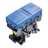
WABCO iABS 4S/2M Standard for Pull Trailers Maintenance Manual (189 pages)
TRAILER ABS SYSTEM WITH PLC AND CAN
Brand:
WABCO
| Category:
Automobile Accessories
| Size: 10.84 MB
Table of Contents
Table of Contents
2
1 General Information
4
Symbols Used in this Document
4
How to Obtain Additional Maintenance, Service and Product Information
4
WABCO TOOLBOX PLUS Software
5
WABCO Academy
5
WABCO Online Product Catalog
5
2 Safety Information
6
Provisions for a Safe Work Environment
6
Note During Servicing the Trailer
7
Trailer Grounding and Protection from Electrostatic Discharge
7
Vehicle Electrical Grounding Guidelines
7
Welding Work on the Trailer
7
3 Introduction
9
Identifying Iabs
9
IABS Trailer ABS Parts
10
What Is Wabco’s Iabs Trailer ABS?
10
System Confi Guration
10
How Trailer ABS Works
11
System Components
11
Ecu/Valve Assembly
11
ABS External Modulator Valve
11
Sensor with Molded Socket
12
Sensor Clip
12
Tooth Wheel
12
Cables for Iabs
13
Iabs Trailer ABS Indicator
13
TOOLBOX PLUS Software
13
Noregon DLA + PLC Adapter
14
Noregon Heavy Duty Trailer Diagnostic Adapter
14
4 ABS Questions and Answers
15
The ECU
15
Power Line Carrier (PLC)
15
ABS Indicator Lamps
16
ABS Indicator Lamp (on Dash)
16
ABS Indicator Lamp (on Trailer)
16
What Is the Function of the ABS Indicator Lamp?
16
What Does the Trailer ABS Indicator Lamp Mean to Service Personnel?
17
Typical ABS Indicator Lamp Mounting Location on Side of Trailer
17
Constant Power
18
Stoplight Power
18
Types of Faults
18
What Is a Fault in the System?
18
What Is an Intermittent Fault?
19
Is an Intermittent Fault Difficult to Locate and Repair?
19
Frequently Asked Questions
19
What Is the Crack Pressure of the ABS Valve?
19
IABS Installation Diagrams
20
5 System Confi Gurations
20
Typical Iabs Trailer Installation
21
Power Cable Wiring Diagrams
29
Hazard Alert Messages
30
Important PLC Information for Blink Code Diagnostics
30
Main Screen
31
TOOLBOX PLUS Software Screens
31
Tire Calibration
32
Sensor Test
33
Service Information
33
Sensor Orientation Test
34
Report Information
35
Save and Print
36
Initial Power-Up Check
37
Power and Ground Checks
37
Blink Code Diagnostics
38
Ignition Power Activation
38
Blink Code Table
39
Diagnostic Table
40
SID/FMI Diagnostic Codes
40
7 Component Replacement
115
Wheel Speed Sensor
116
How to Remove a Sensor
116
How to Install a Senso
116
How to Remove a Standard ABS Relay Valve
117
ABS Relay Valve (Figure 7.3)
117
How to Install a Standard ABS Relay Valve
118
Ecu/Valve Assembly
118
How to Remove the Ecu/Valve Assembly
119
How to Install the Ecu/Valve Assembly
119
Tank-Mounted
120
Bracket-Mounted to Cross Member of Vehicle
121
Mounted to Cross Member of Vehicle
122
8 Sensor Adjustment and Component Testing
123
How to Test Wheel Speed Sensors
123
Sensor Test Procedure
123
Sensor Output Voltage Test
123
Check ABS Functions
124
End of Line Testing
124
ABS External Modulator Valve
124
End of Line Testing Procedure Using TOOLBOX PLUS
125
Sensor Orientation Test Screen
130
End of Line Testing Without TOOLBOX PLUS Software
132
2S/1M Standard
132
Inspect the Sensor and Air Line Installation (2S/2M Standard)
133
Sensor Installation
133
Air Line Installation
133
Perform End of Line Test
136
Sensor Gap Adjustment
136
Trailer Identifi Cation
138
Automatic Lift Axle Troubleshooting
139
Lift Axle Test Rig
151
Standard J560 Connector Wiring Diagram
151
Tag Axle Troubleshooting
152
Axle Load Monitoring Troubleshooting
159
Tire Infl Ation Communication System Troubleshooting
163
Door Ajar System Troubleshooting
168
Integrated Speed Switch System
172
10 Appendix I
175
10 Appendix I
175
Traiier ABS Indicator Lamp on Vehicle Dash
175
Dash-Mounted Trailer Abs Indicator Lamp Operation
176
11 Appendix II
177
11 Appendix II
177
Installing Sensors on Non-ABS-Prepped Axles
177
12 Appendix III
179
12 Appendix III
179
Cable Routing Guidelines
179
Cable Strain Relief Guidelines
180
Excess Cable Length
180
Strain Relief at the ECU – Bracket Mounting
181
Bracket Mounting - Ecu Rear View
181
Strain Relief at the ECU – Tank Mounting
181
Tank Mounting - Ecu Front View
182
Sensor Extension Cables at the ECU
182
Sensor Extension Cables - Ecu Front View
182
Securing WABCO Cables to Air Lines
183
Connection of Cables
183
13 Appendix IV
184
Note During Welding Work on the Trailer
184
Note During Electrostatic Painting the Trailer Frame or Bogie
184
13 Appendix IV
184
Vehicle Electrical Grounding Guidelines
184
14 Appendix V
185
14 Appendix V
185
Parts and Variant List
185
About WABCO
188
Advertisement
Advertisement
Related Products
WABCO IVTM
WABCO iABS 2S/2M Premium
WABCO iABS 4S/2M Premium
WABCO 2S/2M
WABCO 400 500 320 0
WABCO 4S/2M
WABCO 4S/3M
WABCO iABS 2S/1M Standard
WABCO iABS 4S/2M Standard
WABCO OnGuard
WABCO Categories
Automobile Accessories
Control Unit
Door locks
Industrial Equipment
Measuring Instruments
More WABCO Manuals
Login
Sign In
OR
Sign in with Facebook
Sign in with Google
Upload manual
Upload from disk
Upload from URL