Table of Contents
Advertisement
Quick Links
Advertisement
Table of Contents

Subscribe to Our Youtube Channel
Related Manuals for Haussmann TDB342


Summary of Contents for Haussmann TDB342
- Page 1 Operator’s Manual 3.0 HP (Max. Developed) 10 In. Blade 5000 R.P.M. TABLE SAW Model No. TDB342 CAUTION: Safety Instructions ● Before using this Table Saw, Installation ● read this manual and follow Operation ● all its Safety Rules and Maintenance ●...
-
Page 2: Table Of Contents
This HAUSSMANN product is covered by 3-year warranty against workmanship and material defects. In case of any malfunction of your HAUSSMANN tool (failure, missing part, etc.), please contact one of our service technician at our toll free service line at 1-888-267-7713 from 9 am to 9 pm, Monday to Friday, Eastern time. -
Page 3: Power Tool Safety
POWER TOOL SAFETY WARNING WARNING WARNING Before using your table saw, it is critical that you read and understand these safety rules. Before using your table saw, it is critical that you read and understand these safety rules. Before using your table saw, it is critical that you read and understand these safety rules. - Page 4 TABLE SAW SAFETY 1. ALWAYS USE SAW BLADE GUARD, splitter and 12.PROVIDE ADEQUATE SUPPORT to the rear anti-kickback pawls for every operation for which they and the sides of the saw table for long or wide can be used, including through-sawing. Through- workpieces.
-
Page 5: Electrical Requirements And Safety
ELECTRICAL REQUIREMENTS AND SAFETY GROUNDING INSTRUCTIONS POWER SUPPLY REQUIREMENTS IN THE EVENT OF A MALFUNCTION OR WARNING BREAKDOWN, grounding provides a path of least resistance for electric current and reduces the risk of To avoid electrical hazards, fi re hazards or damage to electric shock. -
Page 6: Accessories And Attachments
ACCESSORIES AND ATTACHMENTS CARTON CONTENTS RECOMMENDED ACCESSORIES UNPACKING AND CHECKING CONTENTS WARNING Separate all parts from packing materials. Check each To avoid the risk of personal injury: part with the illustration on the next page and the “Table ● Do not use adjustable (wobble) type dadoes or of Loose Parts”... - Page 7 UNPACKING YOUR TABLE SAW...
-
Page 8: Know Your Table Saw
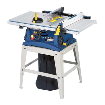
KNOW YOUR TABLE SAW Table Insert Blade Guard Rip Fence Side Table Extension Wing TABLE SAW SPECIFICATIONS Heavy Duty Universal Motor Extension Wing Locking Lever 120V, 60Hz, 15Amps, AC 5000RPM (No-load Speed) Maximum cutting depth: at 90 ....3 inches at 45 ....2-1/2 inches Overload Reset Switch MAXIMUM DEVELOPED HP... -
Page 9: Assembly And Adjustments
ASSEMBLY AND ADJUSTMENTS Assemble table saw to stand (Fig. A, B) Assemble stand (Fig. A) 1. Place protective corrugated cardboard or old blanket 1. Unpack all parts and group by type and size (Fig. A). on fl oor to protect the saw table surface. Refer to parts list for quantities. - Page 10 SAW MOUNTED TO WORK SURFACE (FIG. C) chips or sparks may ignite sawdust or the bag material. 1. If the leg set will not be used, the saw must be Place the dust bag neck opening around the dust chute properly secured to a sturdy workbench using the and tie the dust bag with string.
- Page 11 RIP FENCE (Fig. G) 2. Raise the blade arbor (4) (Fig. I) to the maximum 1. Lift upward on the rip fence handle (1) so that the height by turning the blade raising handwheel holding clamp (2) is fully extended. counterclockwise.
- Page 12 BLADE GUARD ASSEMBLY (FIG. K, L, M) WARNING 1. Set the blade to maximum height and the tilt to zero Improper splitter alignment can cause “kickback” and degrees on the bevel scale with the hand wheels. serious injury. Lock the blade lock knob. Fig.M 2.
- Page 13 INSTALLING TABLE SIDE EXTENSIONS- cont’d ADJUSTING REAR TABLE EXTENSION (FIG. O) 1. Rear table extension should be positioned as close 6. Snap one location seat (5) over the end of the rear as possible to the rear of the table when ripping short table extension tube (3).
- Page 14 RIP FENCE INDICATOR ADJUSTMENT (FIG. Q) Fig. Q-2 1. The rip fence indicator (6) points to the measurement scale (8). The scale shows the distance from the side 90° 45° of the fence to nearest side of the blade. 2. Measure the actual distance with a rule. If there is a difference between the measurement and the indicator, adjust the indicator (6).
- Page 15 BLADE PARALLEL TO THE MITER GAUGE GROOVE Additional blade adjustments (Fig. S) (FIG. R,S) The adjusting mechanism is located on top of blade height adjusting hand wheel under the tabletop. If the WARNING front and rear measurements are not the same, adjust This adjustment was made at the factory, but it should the alignment by the mechanism as follows: be rechecked and adjusted if necessary.
-
Page 16: Operation
OPERATION BASIC SAW OPERATIONS OVERLOAD PROTECTION (FIG. U) This saw has an overload relay button (3) that resets RAISE THE BLADE (FIG. T) the motor after it shuts off due to overloading or low To raise or lower the blade, turn the blade elevation voltage. - Page 17 CUTTING OPERATIONS Fig. W There are two basic types of cuts: ripping and crosscutting. Ripping is cutting along the length and the grain of the workpiece. Crosscutting is cutting either across the width or across the grain of the workpiece. Neither ripping nor crosscutting may be done safely freehand.
- Page 18 BEVEL RIPPING interfere with the proper operation of the sawblade This cut is the same as ripping except the blade bevel guard. When cutting long workpieces, you can make angle is set to an angle other than “0”. a simple support by clamping a piece of plywood to a sawhorse.
- Page 19 MITERING (FIG. BB) WARNING This sawing operation is the same as crosscutting Make sure the screw heads do not stick out from the except the miter gauge is locked at an angle other than bottom of the base, they must be fl ush or recessed. The 90°...
-
Page 20: Maintenance
MAINTENANCE MAINTAINING YOUR TABLE SAW Fig. EE GENERAL MAINTENANCE WARNING For your own safety, turn the switch OFF and remove the switch key. Remove the plug from the power source outlet before maintaining or lubricating your saw. 1. Clean out all sawdust that has accumulated inside the saw cabinet and the motor. -
Page 21: Troubleshooting Guide
TROUBLESHOOTING GUIDE WARNING To avoid injury from an accidental start, turn the switch OFF and always remove the plug from the power source before making any adjustments. • Consult your local Service Center if for any reason the motor will not run. SYMPTOM POSSIBLE CAUSES CORRECTIVE ACTION... -
Page 22: Parts List
PARTS LIST 10 in. TABLE SAW MODEL NO. TDB342 WARNING Any attempt to repair or replace electrical parts on this Table Saw may create a HAZARD unless repair is done by a qualifi ed service technician. Repair service is available at your nearest Service Centre. - Page 23 10 in. TABLE SAW MODEL NO. TDB342 SCHEMATIC FOR SAW...
- Page 24 10 in. TABLE SAW MODEL NO. TDB342 PARTS LIST AND SCHEMATIC FOR STAND I.D. NO Description Size 09D6 FOOT PAD 0A4T FENCE STORAGE CLIP 0EAA BRACKET 0EAP UPPER SUPPORT 0EAY UPPER SUPPORT 0EB8 BOTTOM SUPPORT BRACKET 0EBG BOTTOM SUPPORT BRACKET...
- Page 25 10 in. TABLE SAW MODEL NO. TDB342 PARTS LIST AND SCHEMATIC FOR MOTOR I.D. NO Description Size 0HV8 BALL BEARING 6201ZLU 0HVU BALL BEARING 6200ZZ 0HX9 NEEDLE BEARING 0JAL EXT.TOOTH LOCK WASHER 0JX3 HEX. SOC. SET SCREW M5*0.8-8 0K3A CR.RE. PAN HD. SCREW & WASHER M5*0.8-30...
-
Page 26: Push Stick Plan
PUSH STICK CONSTRUCTION • This is a full-size drawing (actual size) • Use good quality plywood or solid wood • Use 1/2 in. or 3/4 in. material • Push stick MUST be thinner than the width of material being cut Drill Hole For Hanging Notch To Prevent...
Need help?
Do you have a question about the TDB342 and is the answer not in the manual?
Questions and answers