Table of Contents
Advertisement
Instruction Manual
10 IN. JOBSITE TABLE SAW
Model No.: JT2503RN
RONA Code: 89335002
QUESTIONS? 1-866-206-0888
Our Customer service staff is available to help you.
For help with product assembly, to report damaged or missing parts, or for any other
information, please call our toll-free number: 1-866-206-0888.
Register your product
We invite you to register your product online to make future communications easier.
To do so, simply visit our website www.haussmanntools.com.
SAVE THIS MANUAL
You will need this manual for safety instructions, operating procedures, and warranty.
Put it and the original sales invoice in a safe, dry place for future reference.
1
Advertisement
Table of Contents

Related Manuals for Haussmann X-pert JT2503RN


Summary of Contents for Haussmann X-pert JT2503RN
- Page 1 Instruction Manual 10 IN. JOBSITE TABLE SAW Model No.: JT2503RN RONA Code: 89335002 QUESTIONS? 1-866-206-0888 Our Customer service staff is available to help you. For help with product assembly, to report damaged or missing parts, or for any other information, please call our toll-free number: 1-866-206-0888. Register your product We invite you to register your product online to make future communications easier.
-
Page 2: Table Of Contents
TABLE OF CONTENTS SECTION PAGE SECTION PAGE Product Specifications........... Glossary of Terms......... Safety Symbols............. Assembly and Adjustments......Power Tool Safety..........Operation............Table Saw Safety..........Maintenance..........Electrical Requirements and Safety...... Push Stick Pattern......... Accessories and Attachments....... Troubleshooting Guide........Tools Needed for Assembly......... Warranty............ -
Page 3: Safety Symbols
SAFETY SYMBOLS WARNING ICONS Your power tool and its Instruction Manual may contain “WARNING ICONS” (a picture symbol intended to alert you to, and/or instruct you how to avoid, a potentially hazardous condition). Understanding and heeding these symbols will help you operate your tool better and safer. Shown below are some of the symbols you may see. SAFETY ALERT: Precautions that involve your safety. -
Page 4: Power Tool Safety
POWER TOOL SAFETY WEAR PROPER APPAREL. Do not wear GENERAL SAFETY INSTRUCTIONS BEFORE USING loose clothing, gloves, neckties, rings, THIS POWER TOOL bracelets or other jewelry which may Safety is a combination of common sense, staying alert get caught in moving parts. Nonslip footwear is and knowing how to use your power tool. - Page 5 POWER TOOL SAFETY 20. NEVER LEAVE THE TOOL RUNNING WARNING UNATTENDED. TURN THE POWER “OFF”. Do not Dust generated from certain materials can be walk away from a running tool until the blade comes hazardous to your health. Always operate saw in to a complete stop and the tool is unplugged from well-ventilated area and provide for proper dust the power source.
- Page 6 TABLE SAW SAFETY 1. ALWAYS USE SAW BLADE GUARD, riving knife 13. AVOID KICKBACKS (work thrown back towards and anti-kickback pawls for every through–sawing you) by keeping the blade sharp, the rip fence operation. Through–sawing operations are those parallel to the saw blade and by keeping the riving in which the blade cuts completely through the knife, anti-kickback pawls and guards in place, workpiece when ripping or crosscutting.
- Page 7 TABLE SAW SAFETY 21. USE ONLY saw blades recommended with warning 26. NEVER ATTEMPT TO PLUNGE CUT INTO A that the riving knife shall not be thicker than the WORKPIECE by placing it on top of the spinning width of the groove cut by the saw blade and not blade.
- Page 8 TABLE SAW SAFETY SAW BLADE GUARD ASSEMBLY, ANTI-KICKBACK How to Avoid Them and Protect Yourself from ASSEMBLY AND RIVING KNIFE Possible Injury: Your table saw is equipped with a blade guard assembly, a. Be certain that the rip fence is parallel to the saw anti-kickback assembly and riving knife that covers the blade.
-
Page 9: Electrical Requirements And Safety
ELECTRICAL REQUIREMENTS AND SAFETY COMPOUND MITER SAW SAFETY POWER SUPPLY AND MOTOR SPECIFICATIONS GUIDELINES FOR EXTENSION CORDS USE THE PROPER EXTENSION CORD. Make sure WARNING your extension cord is in good condition. Use an To avoid electrical hazards, fire hazards, or damage extension cord heavy enough to carry the current your to the tool, use proper circuit protection. -
Page 10: Accessories And Attachments
ACCESSORIES AND ATTACHMENTS CARTON CONTENTS RECOMMENDED ACCESSORIES Separate all parts from packing materials. Check each part with the illustration on the next page and the “Table WARNING of Loose Parts” to make certain all items are accounted To avoid the risk of personal injury: for before discarding any packing material. - Page 11 UNPACKING YOUR TABLE SAW...
-
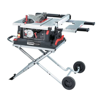
Page 12: Know Your Table Saw
KNOW YOUR TABLE SAW Blade guard Rip fence Mitre gauge Stand up supports Blade elevation handwheel Hand hold Overload reset switch Mitre gauge storage Stand handle ON/OFF switch with key Push stick storage Power cord Blade tilt scale Blade bevel lock handle Stand assembly Wheel Table insert... -
Page 13: Glossary Of Terms
GLOSSARY OF TERMS ANTI-KICKBACK PAWLS – Prevents the workpiece NON-THROUGH SAWING - refers to any cut that does from being kicked upward or back toward the front of the not completely cut through the workpiece. table saw by the spinning blade. OVERLOAD RESET SWITCH –... -
Page 14: Assembly And Adjustments
ASSEMBLY AND ADJUSTMENTS ASSEMBLING THE STAND (FIG. A, B) ASSEMBLING THE WHEELS (FIG. C, C-1) 1. Using the hardware in bag #T, attach one wheel to WARNING the right front leg using the long square-neck bolt (3), Stand may pop up unexpectedly without weight of the flat washers (1), the sleeve (4), the shaft sleeve saw on stand. - Page 15 SETTING UP THE STAND (FIG. A, B, E) Fig. F 1. Remove the band (23) and then release the stand lock hook (17) from both sides of the stand, by sliding it away from the stop screw (20). (Fig. A) 2.
- Page 16 Attach the rubber pad (5) from hardware bag #C, to 5. Clean the outer blade flange (4) and install it onto the inside of the rear table extension (1). Thread the the arbour (5) and against the blade. (Fig. J) screw (6) thru the rubber pad with the screwdriver.
- Page 17 RIVING KNIFE ASSEMBLY (FIG. L, M, N) Fig. N WARNING To avoid injury from an accidental start, make sure the switch is in the OFF position and the plug is disconnected from the power source outlet. Never operate this saw without the riving knife in the correct position.
- Page 18 4. Take the blade guard assembly and locate the red Fig. O sliding locking knob (4) on the back of assembly. (Fig. R) 5. Insert the blade guard assembly onto the riving knife so that the pin (5) engages into slot (6) completely. (Fig.
- Page 19 WARNING WARNING Improper riving knife alignment can cause To avoid serious injury, the table insert (2) must be level with the table. If the table insert is not flush “kickback” and serious injury. with the table, adjust the four bolts (1) with a 4 mm Fig.
- Page 20 45° Stop 5. Place the combination square base (1) into the right 1. Disconnect the saw from the power source. side mitre gauge groove (2) flush against the inside 2. Raise the blade to the maximum elevation. of the mitre gauge groove. 3.
- Page 21 ADJUSTING THE MITRE GAUGE (FIG. AA) If the fence is loose when the handle is in the locked 1. Loosen the lock handle (1) to allow the mitre body (2) position: to rotate freely. Position the mitre body at 90° so the 1.
- Page 22 TABLE EXTENSION SCALE POINTER (FIG. DD) Fig. FF The table extension scale pointer (1) should be at 13 in. on the scale when the extension is in the closed position. If not, loosen the holding screw (2), position the pointer over the 13 in. marker and re-tighten the screw. Fig.
-
Page 23: Operation
OPERATION OVERLOAD PROTECTION (FIG. II) BASIC SAW OPERATIONS This saw has an overload reset button (3) that resets the RAISE THE BLADE (FIG. HH) motor after it shuts off due to overloading or low voltage. To raise or lower the blade, turn the blade elevation If the motor stops during operation, turn the ON / OFF handwheel (1) to the desired blade height, and then switch to the OFF position. - Page 24 CUTTING OPERATIONS WARNING There are two basic types of cuts: ripping and AVOID KICKBACK by pushing forward on the crosscutting. Ripping is cutting along the length and the section of the workpiece that passes between the grain of the workpiece. Crosscutting is cutting either blade and the fence.
- Page 25 BEVEL RIPPING Fig. NN This cut is the same as ripping except the blade bevel angle is set to an angle other than “0°”. RIPPING SMALL PIECES To avoid injury from the blade contact, never make cuts narrower than 1/2 in. wide. 1.
- Page 26 COMPOUND MITRE CROSSCUTTING (FIG. QQ) USING THE WOOD FACING ON THE RIP FENCE 0°~45° BLADE BEVEL & 0°~45° MITRE ANGLE (FIG. SS) This sawing operation combines a mitre angle with a When performing some special cutting operations, you bevel angle. can add a wood facing to either side of the rip fence (2).
- Page 27 6. Use only the correct number of round outside blades and inside chippers as shown in the dado set’s instruction manual. Blade/chippers must not exceed 13/16 in. total in width. 7. Check the saw to ensure that the dado will not strike the housing, insert, or motor when in operation.
-
Page 28: Maintenance
MAINTENANCE MAINTAINING YOUR TABLE SAW Fig. UU GENERAL MAINTENANCE WARNING For your own safety, turn the switch OFF and remove the switch key. Remove the plug from the power source outlet before maintaining or lubricating your saw. 1. Clean out all sawdust that has accumulated inside NOTE: If excessive looseness is observed in any part of the saw cabinet and the motor. - Page 29 REPLACING THE CARBON BRUSHES Fig. WW (FIG. VV, WW) WARNING Always disconnect the plug from the power source before inspecting the brushes. The carbon brushes included with the unit will last approximately 50 hours of running time, or 10,000 ON/OFF cycles. Replace both carbon brushes when either has less than 1/4 in.
-
Page 30: Push Stick Pattern
PUSH STICK PATTERN PUSH STICK CONSTRUCTION • Use good quality plywood or solid wood • Use 1/2 in. (13 mm) or 3/4 in. (19 mm) material • Push stick MUST be thinner than the width of material being cut Drill hole for hanging Notch for prevent hand from slipping... -
Page 31: Troubleshooting Guide
TROUBLESHOOTING GUIDE WARNING To avoid injury from an accidental start, turn the switch OFF and always remove the plug from the power source before making any adjustments. ● If for any reason the motor will not run, contact the Rona Service Centre. PROBLEM POSSIBLE CAUSES CORRECTIVE ACTION... -
Page 32: Warranty
WARRANTY FULL THREE YEAR WARRANTY Thank you for investing in a HAUSSMANN XPERT power tool. These products have been made to demanding, high-quality standards and are guaranteed for domestic use against manufacturing faults for a period of 36 months from the date of purchase. -
Page 33: Parts List
PARTS LIST 10 IN. JOB SITE TABLE SAW MODEL NO. JT2503RN WARNING Any attempt to repair or replace electrical parts on this table saw may create a HAZARD unless repair is done by a qualified service technician. Repair service is available at your nearest Service Centre. PARTS LIST FOR TABLE SAW SCHEMATIC I.D. - Page 34 10 IN. JOB SITE TABLE SAW MODEL NO. JT2503RN SCHEMATIC...
- Page 35 10 IN. JOB SITE TABLE SAW MODEL NO. JT2503RN STAND I.D. Description Size I.D. Description Size 0J4E FLAT WASHER φ6*13-1 2FVR LOCK ROD 0J4F FLAT WASHER φ8*16-2.5 2FVS SPRING 0J4R FLAT WASHER φ10*20-3 2GU2 PLUG-BUTTON 0J53 FLAT WASHER φ8.4*24-2 2H9F MOVABLE COVER 0JAZ WAVE WASHER...
- Page 36 10 IN. JOB SITE TABLE SAW MODEL NO. JT2503RN SCHEMATIC FOR STAND...
- Page 37 10 IN. JOB SITE TABLE SAW MODEL NO. JT2503RN MOTOR I.D. Description Size QTY I.D. Description Size 0HV4 BALL BEARING 10ZD FIELD ASS’Y 0HX9 NEEDLE BEARING 10ZR ARBOR SHAFT 0JB8 WAVE WASHER BWW-6200 10ZS COLLAR 0JBA WAVE WASHER BWW-6203 10ZT BEARING RETAINER 0JE0 C-RING...
Need help?
Do you have a question about the X-pert JT2503RN and is the answer not in the manual?
Questions and answers