Table of Contents

Related Manuals for Haussmann X-PERT HETS-001


Summary of Contents for Haussmann X-PERT HETS-001
- Page 1 Operator’s Manual 10’’ JOB SITE TABLE SAW Model No. HETS-001 CAUTION: Safety Instructions ● Installation Before using this Table Saw, ● Operation read this manual and follow ● Maintenance all its Safety Rules and ● Parts List Operating Instructions ●...
-
Page 2: Table Of Contents
This HAUSSMANN X-PERT product is covered by 3-year warranty against workmanship and material defects. In case of any malfunction of your HAUSSMANN X-PERT tool (failure, missing part, etc.), please contact one of our service technician at our toll free service line at 1-866-599-5916 Ext 2 from 9 am to 9 pm, Monday to Friday, Eastern time. -
Page 3: Safety Symbols
SAFETY SYMBOLS WARNING ICONS Your power tool and Instruction Manual may contain “WARNING ICONS” (a picture symbol intended to alert you to, and/or instruct you how to avoid, a potentially hazardous condition). Understanding and following these symbols will help you to operate your tool better and more safely. Shown below are some of the symbols you may see. -
Page 4: Power Tool Safety
POWER TOOL SAFETY GENERAL SAFETY INSTRUCTIONS 11. WEAR PROPER APPAREL. Do not wear loose BEFORE USING THIS POWER TOOL clothing, gloves, neckties, rings, bracelets or any Safety is a combination of common sense, staying alert other jewelry that can get caught in the tool’s and knowing how to use your power tool. - Page 5 POWER TOOL SAFETY 20. NEVER LEAVE THE TOOL RUNNING UNATTENDED. TURN THE POWER “OFF”. Do not walk away from a running tool until the blade comes to a complete stop and the tool is unplugged from the power source. 21. DO NOT OVERREACH. Keep proper footing and balance at all times.
- Page 6 TABLE SAW SAFETY 1. ALWAYS USE A SAW BLADE GUARD, splitter 13. AVOID KICKBACKS (work thrown back towards and anti-kickback pawls for every through–sawing you) by keeping the blade sharp, the rip fence operation. Through–sawing operations are those parallel to the saw blade and by keeping the splitter, in which the blade cuts completely through the anti-kickback pawls and guards in place, aligned workpiece when ripping or crosscutting.
-
Page 7: Electrical Requirements And Safety
ELECTRICAL REQUIREMENTS AND SAFETY COMPOUND MITER SAW SAFETY or a #14 wire with a 15 A time-lag fuse. NOTE: When GROUNDING INSTRUCTIONS using an extension cord on a circuit with a #14 wire, the extension cord must not exceed 25 feet in length. IN THE EVENT OF A MALFUNCTION OR Before connecting your tool to the power line, make sure BREAKDOWN, grounding provides the path of least... -
Page 8: Accessories And Attachments
ACCESSORIES AND ATTACHMENTS CARTON CONTENTS RECOMMENDED ACCESSORIES Separate all parts from packing materials. Check each part with the illustration on the next page and the “Table WARNING of Loose Parts” to make certain all items are accounted To avoid the risk of personal injury: for before discarding any packing material. - Page 9 UNPACKING YOUR TABLE SAW...
-
Page 10: Know Your Table Saw
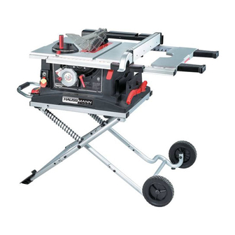
KNOW YOUR TABLE SAW Blade Guard Rip fence Mitre Gauge Stand up Supports Blade elevation handwheel Hand hold Overload reset switch Mitre gauge storage Stand handle Push stick storage ON/OFF switch with key Blade tilt scale Blade bevel lock handle Stand assembly Roller wheel Table insert... -
Page 11: Glossary Of Terms
GLOSSARY OF TERMS OVERLOAD RESET SWITCH – Resets the ANTI-KICKBACK PAWLS – Prevents the workpiece thermocouple and provides a way to restart the saw from being kicked upward or back toward the front of the motor if it overloads or overheats. table saw by the spinning blade. -
Page 12: Assembly And Adjustments
ASSEMBLY AND ADJUSTMENTS ASSEMBLING THE STAND (FIG. A, B) ASSEMBLING THE WHEELS (FIG. C, C-1) 1. Attach two collars (1) to each roller wheel (2). WARNING 2. Attach one roller wheel assembly to the right front leg using the long square-neck bolt (3), the shaft sleeve Stand may pop up unexpectedly without weight of (4), and the nut (5), as shown. - Page 13 MOUNTING THE SAW TO A WORK SURFACE IF THE contacting the floor and are at a similar angle to the STAND IS NOT USED (FIG. E) floor. NOTE: Make sure the table saw is locked securely in WARNING position. Adjust the levelling pad to make sure the table Failure to provide a sawdust fall-through hole when saw is totally stable.
- Page 14 ASSEMBLING THE HANDWHEEL HANDLE (FIG. H) Fig. I-1 Thread the handwheel handle (1) into the handwheel hole (2), and then tighten the nut against the handwheel with a 10 mm wrench. NOTE: If the handle bolt becomes loose, remove the plastic end cap and this will allow you to tighten securely.
- Page 15 FIG. J BLADE GUARD ASSEMBLY (FIG. L, M) WARNING To avoid injury from an accidental start, make sure the switch is in the OFF position and the plug is disconnected from the power source outlet. ● When installing the blade guard, cover the blade teeth with a piece of folded cardboard to protect yourself from possible injury.
- Page 16 Removing the blade guard assembly (Fig. L) 6. If the blade and splitter are not correctly aligned: a. Remove the blade guard by removing the wing WARNING bolt that locks the guard in place. To avoid injury from an accidental start, make sure b.
- Page 17 STORAGE (FIG. N, O) ADJUSTING THE 90° AND 45° POSITIVE STOPS Rip fence and mitre gauge (Fig. N) (FIG. Q, R) Storage brackets for the rip fence (4) and mitre gauge (2) Your saw has positive stops that will quickly position the are located on the right side of the saw housing.
- Page 18 Fig. R 9. If the ruler touches the marked tooth at the front and rear position, no adjustment is needed at this time. If not, perform the adjustment procedure described in next section. Fig. S BLADE TILT POINTER 1. When the blade is positioned at 90°, adjust the blade tilt pointer to read 0°...
- Page 19 ADJUSTING THE MITRE GAUGE (FIG. U) If the fence is loose when the handle is in the locked position: 1. Loosen the lock handle (1) to allow the mitre body (2) to rotate freely. Position the mitre body at 90° so the 1.
- Page 20 TABLE EXTENSION SCALE POINTER (FIG. X) Fig. Z The table extension scale pointer (1) should be at 13 inches on the scale when the extension is in the closed position. If not, loosen the holding screw (2), position the pointer over the 13 inch marker and re-tighten the screw.
-
Page 21: Operation
OPERATION OVERLOAD PROTECTION (FIG. CC) BASIC SAW OPERATIONS This saw has an overload reset button (3) that resets the RAISE THE BLADE (FIG. BB) motor after it shuts off due to overloading or low voltage. To raise or lower the blade, turn the blade elevation If the motor stops during operation, turn the ON / OFF handwheel (1) to the desired blade height, and then switch to the OFF position. - Page 22 CUTTING OPERATIONS WARNING There are two basic types of cuts: ripping and AVOID KICKBACK by pushing forward on the crosscutting. Ripping is cutting along the length and the section of the workpiece that passes between the grain of the workpiece. Crosscutting is cutting either blade and the fence.
- Page 23 BEVEL RIPPING Fig. HH This cut is the same as ripping except the blade bevel angle is set to an angle other than “0 ”. RIPPING SMALL PIECES To avoid injury from the blade contact, never make cuts narrower than 1/2’’ wide. 1.
- Page 24 COMPOUND MITRE CROSSCUTTING (FIG. KK) USING THE WOOD FACING ON THE RIP FENCE 0°~45° BLADE BEVEL & 0°~45° MITRE ANGLE (FIG. MM) This sawing operation combines a mitre angle with a When performing some special cutting operations, you bevel angle. can add a wood facing to either side of the rip fence (2).
- Page 25 6. Use only the correct number of round outside blades and inside chippers as shown in the dado set’s instruction manual. Blade/chippers must not exceed 13/16’’ total in width. 7. Check the saw to ensure that the dado will not strike the housing, insert, or motor when in operation.
-
Page 26: Maintenance
MAINTENANCE Fig. OO MAINTAINING YOUR TABLE SAW GENERAL MAINTENANCE WARNING For your own safety, turn the switch OFF and remove the switch key. Remove the plug from the power source outlet before maintaining or lubricating your saw. 1. Clean out all sawdust that has accumulated inside the saw cabinet and the motor. - Page 27 REPLACING THE CARBON BRUSHES NOTE: To reinstall the same brushes, first make sure (FIG. PP, QQ) the brushes go back in the way they came out. This will avoid a break-in period that reduces motor performance and increases wear. WARNING Always disconnect the plug from the power source Fig.
-
Page 28: Troubleshooting Guide
TROUBLESHOOTING GUIDE WARNING To avoid injury from an accidental start, turn the switch OFF and always remove the plug from the power source before making any adjustments. ● If for any reason the motor will not run, contact Service Centre. PROBLEM POSSIBLE CAUSES CORRECTIVE ACTION... -
Page 29: Parts List
PARTS LIST 10’’ JOB SITE TABLE SAW MODEL NO. RETS-001 WARNING Any attempt to repair or replace electrical parts on this Table Saw may create a HAZARD unless repair is done by a qualified service technician. Repair service is available at your nearest Service Centre. PARTS LIST FOR TABLE SAW SCHEMATIC A I,D, Description... - Page 30 10’’ JOB SITE TABLE SAW MODEL NO. RETS-001 SCHEMATIC A...
- Page 31 10’’ JOB SIDE TABLE SAW MODEL NO. RETS-001 PARTS LIST FOR SAW SCHEMATIC B I.D. Description Size I.D. Description Size 0901 BUSH 0KJ0 CAP HD. SQ.NECK BOLT M6*1.0-16 0908 FLAT WASHER 0KJ7 CAP HD. SQ.NECK BOLT M8*1.25-16 0909 FLAT WASHER 0KMY HEX.
- Page 32 10’’ JOB SIDE TABLE SAW MODEL NO. RETS-001 SCHEMATIC B...
- Page 33 10’’ JOB SITE TABLE SAW MODEL NO. RETS-001 STAND I.D. Description Size QTY I.D. Description Size 0J4E FLAT WASHER φ6*13-1 2FUC LOCK LEVEL 0J4F FLAT WASHER φ8*16-2.5 2FUD COLLAR 0J53 FLAT WASHER φ8.4*24-2 2FUK COVER 0JAZ WAVE WASHER WW-6 2FUM COMPRESSION SPRING 0JB2 WAVE WASHER...
- Page 34 10’’ JOB SITE TABLE SAW MODEL NO. RETS-001 SCHEMATIC FOR STAND...
- Page 35 10’’ TABLE SAW MODEL NO. RETS-001 MOTOR I.D. Descrption Size 0HX9 NEEDLE BEARING 0JB8 WAVE WASHER 0JX3 HEX. SOC. SET SCREW M5*0.8-8 0K3F CR. RE. PAN HD. SCREW & WASHER M5*0.8-20 0K44 CR. RE. PAN HD. SCREW & WASHER M5*0.8-12 0KTA STRAIN RELIEF 0QET...
-
Page 36: Push Stick Plan
PUSH STICK CONSTRUCTION ● Use good quality plywood or solid wood ● Use 1/2’’ or 3/4’’ material ● Push stick MUST be thinner than the width of material being cut Drill Hole For Hanging Notch To Prevent Hand From Slipping Cut Here To Push 1/2’’...
Need help?
Do you have a question about the X-PERT HETS-001 and is the answer not in the manual?
Questions and answers