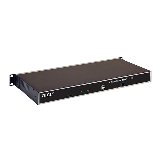
Digi ConnectPort LTS 8 Quick Start Manual
Hide thumbs
Also See for ConnectPort LTS 8:
- Command reference manual (169 pages) ,
- Quick start manual (2 pages) ,
- User manual (163 pages)
Advertisement
Quick Start Guide
ConnectPort® LTS 8/16/32
1
Verify your components
2
Connect the hardware
1. Connect the Ethernet cable to the Ethernet 1 port.
2. Connect the serial devices to the serial ports, following the pin position information below. If serial devices are EIA- 422/485, see section 4, step 6.
3. Connect the power supply to the POWER connector.
4. Connect the XBee antenna, if available.
Ports, connectors, LEDs, and buttons
© 2016 Digi International Inc.
Digi, Digi International, and the Digi logo are trademarks or registered trademarks in the United States and other countries worldwide. All other trademarks mentioned in this document are the
property of their respective owners.
Welcome to your Digi product
Get started: This guide helps you with initial product setup. Need more? Find additional product support at
www.digi.com/support/connectportlts. Or connect to the online documentation by scanning this code:
Digi Technical Support: Digi offers multiple support plans to help you get the most out of your product. For
information on Technical Support plans and pricing, contact us at 877.912.3444 or visit www.digi.com/support.
Documentation feedback: To provide feedback on this documentation, send an email to techcomm@digi.com.
Verify that you have all included equipment. If any item is missing or damaged, contact your supplier.
Included equipment
Pin # on 10-
Pin # on
wire connector
8- wire
connector
1
2
1
2
3
4
3
5
4
5
6
7
6
7
8
8
9
10
*Use the Altpin setting to swap these two signals.
EIA-232
MEI versions only
EIA-422/485
EIA-485
Full-Duplex
Half-Duplex
RI
N/A
TxD-
DSR*
DATA-
RxD-
RTS
RTS+
N/A
CGND
CGND
CGND
N/A
TxD
TxD+
RxD
RxD+
DATA+
SGND
SGND
SGND
CTS
CTS+
N/A
DTR
RTS-
N/A
N/A
DCD*
CTS-
Advertisement
Table of Contents

Summary of Contents for Digi ConnectPort LTS 8
- Page 1 *Use the Altpin setting to swap these two signals. © 2016 Digi International Inc. Digi, Digi International, and the Digi logo are trademarks or registered trademarks in the United States and other countries worldwide. All other trademarks mentioned in this document are the property of their respective owners.
- Page 2 Download required software Digi provides several utilities that discover devices present on a network. You will need to download either the Device Discovery Utility or Digi Port Authority - Remote. Navigate to www.digi.com/support/connectportlts and select Utilities from the Product Support tab. A list of available downloadable utilities for your operating system appears.


Need help?
Do you have a question about the ConnectPort LTS 8 and is the answer not in the manual?
Questions and answers