
Related Manuals for National Instruments FD-11634


Summary of Contents for National Instruments FD-11634
- Page 1 National Instruments FD-11634 Manual Get Pricing & Availability at ApexWaves.com Call Today: 1-800-915-6216 Email: sales@apexwaves.com https://www.apexwaves.com/modular-systems/national-instruments/fielddaq/FD-11634...
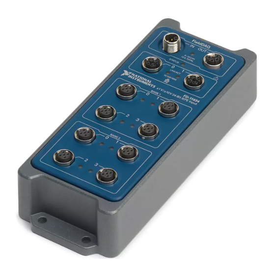
- Page 2 FD-11634 8-Channel Sound and Vibration Input Device for FieldDAQ The FieldDAQ FD-11634 is an IP65/IP67-rated eight-channel sound and vibration input device that incorporates a TEDS input path and IEPE signal excitation source that can be enabled or disabled, removing the need for external sensor power. It can be networked and synchronized with IEEE 802.1AS devices.
-
Page 3: Table Of Contents
Reserving the Device in MAX..................39 STATUS LED..........................39 Resetting the FieldDAQ to Factory-Default Settings............. 40 Mounting..........................41 Mounting Requirements....................43 Dimensions........................45 Mounting the Device Directly on a Flat Surface............45 Alternate Mounting Configurations................47 Firmware..........................49 2 | ni.com | FD-11634 User Guide... -
Page 4: Fd-11634 Basic Information
FieldDAQ accessories and ordering information, refer to the pricing section of the FD-11634 product page at ni.com. Table 2. FD-11634 Cables and Accessories Cable/Accessory Part Number IP67 Power Supply 147464-01 PS-16 Power Supply 781094-01 FD-11634 User Guide | © National Instruments | 3... -
Page 5: Safety Guidelines
FD-11634 Safety, Environmental, and Regulatory Information Safety Guidelines Caution Do not operate the FD-11634 in a manner not specified in this user guide. Product misuse can result in a hazard. You can compromise the safety protection 4 | ni.com | FD-11634 User Guide... -
Page 6: Emc Guidelines
NI for repair. The FD-11634 is rated for use in DRY or WET LOCATIONS. Hazardous voltages may not be connected to the device. A hazardous voltage is a voltage greater than 42.4 V peak voltage or 60 V DC in DRY LOCATIONS, and 22.6 V peak or 35 V DC in WET LOCATIONS. -
Page 7: Unpacking
Unpacking The FD-11634 ships in an antistatic package to prevent electrostatic discharge (ESD). ESD can damage several components on the device. Notice Never touch the exposed pins of connectors. To avoid ESD damage in handling the device, take the following precautions: •... -
Page 8: Setting Up The Fielddaq Device
Align and connect one end of the Ethernet cable to Ethernet port 0 on the device, and the other end directly to your computer or any network connection on the same subnet as your computer. FD-11634 User Guide | © National Instruments | 7... - Page 9 Wiring External Power to the FieldDAQ Device. The FieldDAQ device requires an external power supply that meets the specifications listed in the FD-11634 Specifications. The Power LED turns on. Refer to Power LED for information about Power LED status.
- Page 10 Enter the hostname of the device. The default hostname is FD11634- <serial number>. Click Add Selected Devices. The FieldDAQ device icon changes from white to dark grey, indicating that it is recognized and present on the network. FD-11634 User Guide | © National Instruments | 9...
- Page 11 Reserve Network Device button. Refer to Reserving the Device in MAX for more information. 10. Self-test your device in MAX by expanding Devices and Interfaces»Network Devices, right-clicking your FieldDAQ device, and selecting Self-Test. Self-test performs a brief 10 | ni.com | FD-11634 User Guide...
-
Page 12: Power Connectors And Wiring
IN OUT Internal Circuit Chassis Ground The FieldDAQ device requires an external power source connected between the V and C terminals, as described in Power Requirements in the FD-11634 Specifications. The FieldDAQ FD-11634 User Guide | © National Instruments | 11... -
Page 13: Power Connectors
FD-11634 Basic Information. The FD-11634 has a maximum device power consumption of 10 W. Each FieldDAQ filters and regulates the supplied power for its tasks. When FieldDAQ devices are linked together through the power IN and power OUT connectors, the total current consumption of the chain equals the sum of every linked FieldDAQ device’s current consumption. -
Page 14: Power Led
If the power source is connected to the power connector using long wiring with high DC resistance, the voltage at the power connector may be significantly lower than the specified voltage of the power source. FD-11634 User Guide | © National Instruments | 13... -
Page 15: Signal Input Connectors And Measurements
Refer to Safety Voltages in the FD-11634 Specifications for information about the maximum voltage from terminal to chassis ground. Signal Input Connectors and Measurements The following figures show the signal input circuitry and block diagram of the FD-11634. Figure 8. FD-11634 Input Circuitry 4 mA... -
Page 16: Signal Input Connectors
Signal Input Connectors The FD-11634 features eight 5-pin A-coded M12 connectors: Bank 1 connectors 0 through 3 and Bank 2 connectors 0 through 3. The following figure shows the pinout of a signal input connector. - Page 17 M12-BNC Cabling You can use the SHM125M-BNCF and SHM125M-BNCF-RA cables with the FD-11634. The following figure shows the pinouts for the M12 and BNC connector on the cables. Figure 11. SHM125M-BNCF and SHM125M-BNCF-RA Cable Pinout AI–...
-
Page 18: Signal Input Leds
LED settings on the Settings tab. Note When you turn off the LEDs in MAX, the FieldDAQ device controls and sets the state of the LED. You cannot configure an LED while a task is running. FD-11634 User Guide | © National Instruments | 17... -
Page 19: Connecting Input Signals
The FD-11634 provides an IEPE excitation current for each channel to measure the IEPE sensors. Typical IEPE sensors have a case that is electrically isolated from the IEPE electronics. As a result, connecting the sensor to the FD-11634 results in a floating connection even though the case of the sensor is grounded. -
Page 20: Input Coupling
AI+ and AI- drops below 180 mV. Refer to the FD-11634 Specifications for additional short circuit thresholds. When a short circuit is detected, the Overcurrent status is set in NI-DAQmx and the Signal Input LED lights red. - Page 21 Reducing measurement Control applications noise Refer to the FD-11634 Specifications for details on the amount of variation in the response you can expect for different input frequency ranges. Frequency Response of FieldDAQ Filters The FieldDAQ device uses a combination of analog and digital filtering to provide an accurate representation of in-band signals and reject out-of-band signals.
- Page 22 Call the AI.FilterDelay property in NI-DAQmx to read the input delay. FD-11634 User Guide | © National Instruments | 21...
- Page 23 It is common to use the comb filter with a specific sample rate to align the notches of the transition band thereby removing a specific noise-source frequency from measurements. 22 | ni.com | FD-11634 User Guide...
- Page 24 Constant Delay Comb Frequency (Hz) Refer to the FD-11634 Specifications for details on the amount of variation in the passband gain and signal delay you can expect for different input frequency ranges. FD-11634 User Guide | © National Instruments | 23...
-
Page 25: Data Rates
Undershoot Comb Time Refer to the FD-11634 Specifications for details on the amount of variation in the response you can expect for different input frequency ranges. Data Rates You can use the 13.1072 MHz, 12.8 MHz, 12.288 MHz, and 10.24 MHz timebases to generate data rates. -
Page 26: Programming The Fielddaq Device
When using multiple FieldDAQ devices in a task that contains channels for a Delta-Sigma device, such as the FD-11634, ensure that one of those channels is the first in your channel list. FD-11634 User Guide | © National Instruments | 25... -
Page 27: Time-Based Triggers
Network-synchronized devices can also take advantage of time-based synchronization features in NI-DAQmx. Certain triggers can be specified in terms of time of day. Time-based triggers and multidevice tasks (spanning multiple network-synchronized FieldDAQ devices) can help simplify programming for large systems. 26 | ni.com | FD-11634 User Guide... -
Page 28: Timebases
Refer to the Time Triggering topic in the NI-DAQmx Help for more information on accessing time-based features in the NI-DAQmx API. Timebases The following figure shows the FD-11634 clock routing circuitry and timebases. Figure 20. Clock Routing Circuitry 13.1072 MHz Timebase 12.8 MHz Timebase... -
Page 29: More Information About Synchronization
NI Linux Real-Time controller, another FieldDAQ device, or any network connection on the same subnet. Refer to Topology Options for more information about using these ports in various topologies. 28 | ni.com | FD-11634 User Guide... -
Page 30: Ethernet Leds
Table 10. LED State/Device Status LED State Device Status Ethernet link Blinking, fast (12 blinks/s) Ethernet activity. Connected at 1,000 Mbit/s. Blinking, moderate (6 blinks/s) Ethernet activity. Connected at 100 Mbit/s. FD-11634 User Guide | © National Instruments | 29... -
Page 31: Internal Ethernet Switch
IEEE 1588 delay request-response default PTP profile (sometimes referred to as "default profile"). When so configured, it can synchronize local measurement signals to other devices across an IP subnetwork and can serve as a bridge, synchronizing 1588 devices 30 | ni.com | FD-11634 User Guide... -
Page 32: Topology Options
905x, or cDAQ-9132/9133/9134/9135/9136/9137 for LabVIEW Real-Time • Node—Can be any FieldDAQ device or IEEE 802.1AS-compliant CompactDAQ chassis, such as the cDAQ-9185/9189 For more information about designing Ethernet measurement systems, visit ni.com/info enter fdenet FD-11634 User Guide | © National Instruments | 31... - Page 33 You must configure the network properly with a recommended external switch before creating redundant links in the network. Refer to External Switch Requirements for information about what to look for in an external switch. 32 | ni.com | FD-11634 User Guide...
- Page 34 You must configure the network properly with a recommended external switch before creating redundant links in the network. Refer to External Switch Requirements information about what to look for in an external IEEE 802.1AS switch. FD-11634 User Guide | © National Instruments | 33...
-
Page 35: External Switch Requirements
External Switch Requirements To meet the minimum requirements for successful operation with FieldDAQ devices, any switch directly connected to the FieldDAQ device should be compliant with IEEE 802.1Q bridges and bridged networks. 34 | ni.com | FD-11634 User Guide... -
Page 36: Connecting To A Real-Time Controller
Sync, cRIO-904x/905x, and cDAQ-9132/9133/9134/9135/9136/9137 for LabVIEW Real-Time. To network the FieldDAQ device to a Real-Time controller, you need the following items. The cDAQ-9138/9139 for LabVIEW Real-Time controllers will not work in this configuration. FD-11634 User Guide | © National Instruments | 35... - Page 37 If you have problems installing your software, go to ni.com/support/daqmx. Set up your Real-Time controller hardware and install software to it as instructed in the getting started or quick start document for the Real-Time controller. 36 | ni.com | FD-11634 User Guide...
- Page 38 Wiring External Power to the FieldDAQ Device. The FieldDAQ device requires an external power supply that meets the specifications listed in the FD-11634 Specifications. The Power LED turns on. Refer to Power LED for information about Power LED status.
- Page 39 M12 connectors must be mated to cables or have caps installed on them to meet IP65/IP67 requirements. Cover the unused connectors with the included plastic caps whenever water, dust, or dirt are present. Note Avoid long periods of exposure to sunlight. 38 | ni.com | FD-11634 User Guide...
-
Page 40: Troubleshooting Device Connectivity
Agreeing to override the reservation forces the FieldDAQ device to be reserved by the current user. STATUS LED The FieldDAQ device has a STATUS LED. FD-11634 User Guide | © National Instruments | 39... -
Page 41: Resetting The Fielddaq To Factory-Default Settings
Turn off and then turn on the power source to the device. The FieldDAQ device factory-set defaults are listed in the following table. Table 13. Device Default Settings Attribute Value Hostname FD11634-<serial number> DHCP or Link Local 40 | ni.com | FD-11634 User Guide... -
Page 42: Mounting
75 °C or less. However, to ensure proper functionality during use above 75 °C, you must mount the FieldDAQ device in the reference mounting configuration shown in the following figure. Observe the following guidelines to mount the FieldDAQ device in the reference mounting configuration. FD-11634 User Guide | © National Instruments | 41... - Page 43 Before using any mounting methods, record the serial number from the back of the FieldDAQ device so that you can identify it in MAX. You will be unable to read the serial number after you mount the device. 42 | ni.com | FD-11634 User Guide...
-
Page 44: Mounting Requirements
10 A TOTAL 76.2 mm (3.00 in.) STATUS All Around LINK/ACT Cooling 10/100/1000 SYNC Dimensions Allow the appropriate space in front of the device for cabling clearance, as shown in the following figure. FD-11634 User Guide | © National Instruments | 43... - Page 45 38.7 mm 76.2 mm (1.50 in.) (3.00 in.) Measure the Measure the ambient ambient temperature temperature here here 25.4 mm 76.2 mm 76.2 mm 25.4 mm (1.00 in.) (3.00 in.) (3.00 in.) (1.00 in.) 44 | ni.com | FD-11634 User Guide...
-
Page 46: Dimensions
M5 or 10-32 panhead or sockethead cap screws appropriate for the surface. Complete the following steps to mount the FieldDAQ device directly on a flat surface. Prepare the surface for mounting the device using the surface mounting dimensions. FD-11634 User Guide | © National Instruments | 45... - Page 47 Fasten the device to the surface using the M5 or 10-32 screws. Tighten the screws to a maximum torque of 2.5 N · m (25.0 lb · in.). Figure 35. Fastening the Device to the Surface FieldDAQ 9-30 V 10 A TOTAL STATUS LINK/ACT 10/100/1000 SYNC 46 | ni.com | FD-11634 User Guide...
-
Page 48: Alternate Mounting Configurations
Attach the DIN rail clip to the FieldDAQ device and bracket panel using the 8-32 x 1/4 in. screws included in the kit. Tighten the screws to a maximum torque of 1.3 N · m (11.5 lb · in.). FD-11634 User Guide | © National Instruments | 47... - Page 49 You can also horizontally mount the FieldDAQ device to the DIN rail. Clip the device onto the DIN rail. Figure 37. DIN Rail Clip Parts Locator 1. DIN rail clip 2. DIN rail spring 3. DIN rail 48 | ni.com | FD-11634 User Guide...
-
Page 50: Firmware
M12 connectors must be mated to cables or have caps installed on them to meet IP65/IP67 requirements. Cover the unused connectors with the included plastic caps whenever water, dust, or dirt are present. FD-11634 User Guide | © National Instruments | 49... - Page 51 NI-DAQmx 18.6 or later. FieldDAQ The FD-11634 Quick Start, packaged with your device, describes how to install your NI-DAQmx for Windows software, how to set up your FieldDAQ device, and confirm that your device is operating properly.
- Page 52 You can use the NI-DAQmx .NET class library to communicate with and control an NI data acquisition (DAQ) device. Documentation for the NI-DAQmx .NET class library is available by selecting Start»All Programs»National Instruments»NI-DAQmx»NI-DAQmx FD-11634 User Guide | © National Instruments | 51...
- Page 53 Select Start»All Programs»National Instruments»NI-DAQmx»NI-DAQmx Help. The NI-DAQmx C Reference Help describes the NI-DAQmx Library functions, which you can use with National Instruments data acquisition devices to develop instrumentation, acquisition, and control applications. Select Start»All Programs»National Instruments»NI-DAQmx» Text-Based Code Support»NI-DAQmx C Reference Help.
- Page 54 FD-11634 User Guide | © National Instruments | 53...
- Page 55 NI trademarks. Other product and company names mentioned herein are trademarks or trade names of their respective companies. For patents covering NI products/technology, refer to the appropriate location: Help»Patents in your software, the file on your media, or the National Instruments Patent Notice at . You can find patents.txt ni.com/patents...
Need help?
Do you have a question about the FD-11634 and is the answer not in the manual?
Questions and answers