
Subscribe to Our Youtube Channel
Related Manuals for Bien Air iOptima INT


Summary of Contents for Bien Air iOptima INT
- Page 1 iOptima ENG INSTALLATION INSTRUCTIONS. Compatible with iPod touch from 6th generation and iPad mini from 4th generation Rx Only REF 2100354-0004/2020.06...
- Page 2 Set iOptima REF 1700704-001 1x REF 1x REF 1x REF 1x REF 1x REF 1x REF REF 1502475-001 1600677-001 1600809-001 1601074-001 1500666-001 1502568-001 1300067-001 1x REF 1x REF 3300404-001 3300403-001 Set iOptima REF 1700705-001 1x REF 2x REF 2x REF 1x REF 1x REF 1x REF...
- Page 3 Set iOptima REF 1700706-001 PLUS 1x REF 1x REF 1x REF 1x REF 1x REF 1x REF 1x REF 1502475-001 1600677-001 1600809-001 1600755-001 1600606-001 1601076-001 1500666-001 1x REF 1x REF 1x REF 1x REF 1x REF 1502568-001 1300067-001 3300404-001 3300403-001 1303711-010 Set iOptima REF 1700730-001...
- Page 4 Set iOptima REF 1700732-001 1x REF 1x REF 1x REF 1x REF 1x REF 1x REF 1x REF 1600809-001 1600606-001 1601076-001 1500666-001 1502568-001 1300067-001 1303711-010 Options 1x REF 1x REF 1x REF 1x REF 1x REF 1x REF 1x REF 1502620-001 1502621-001 1502622-001...
-
Page 5: Table Of Contents
Table of contents Symbols........2 procedure ........20 5.3.8 DMX3 with 1 Piezo Scaler Identification and Intended diagram ........21 use ........... 2 5.3.9 DMX3 with peristaltic pump on Identification .........2 Piezo Scaler output (without Intended use .........3 DMS) diagram ......22 Notation .........3 5.3.10 DMX3 with 1 Piezo Scaler and peristaltic pump diagram ..23 Electromagnetic... -
Page 6: Symbols
1 Symbols Sign Description Sign Description Non-ionizing electromagnetic radiation CE Marking with number of the notified body. (60417). Manufacturer. Alternating current. Reference number. Main switch - Power OFF. Serial number. Main switch - Power ON. CAUTION! In accordance with federal law Rx Only (USA), this device is only available for sale Sound alerts. -
Page 7: Intended Use
2.2 Intended use Product intended for professional use only. The iOptima systems are only intended for use in general dentistry, restorative dentistry, oral surgery, implantology and endodontics procedure by dentists and dental professionals in a dental office. 2.3 Notation • A, B, C, etc. Text preceded by a letter indicates a procedure to be carried out step-by-step. -
Page 8: Electromagnetic Compatibility - Emissions & Immunity
⚠ CAUTION Since this device is intended to be used adjacent to or stacked with other equipment, the responsibility of verifying normal operation in the configuration in which it will be used falls onto the dental unit manufacturer. 3.2 Electromagnetic compatibility – emissions & immunity Guidance and manufacturer’s declaration –... - Page 9 Guidance and manufacturer’s declaration – Electromagnetic immunity The iOptima is intended for use in the electromagnetic environment specified below. The customer or the user of the iOptima must ensure that it is actually used in such an environment. Electromagnetic environment - Immunity test IEC 60601 test level Compliance level guidance...
- Page 10 Electromagnetic environment - Immunity test IEC 60601 test level Compliance level guidance Field strengths from fixed RF Conducted transmitters, as determined by disturbances 0,15 MHz – 80 MHz 0,15 MHz – 80 MHz an electromagnetic site induced by RF in ISM and in ISM bands fields survey...
-
Page 11: Description
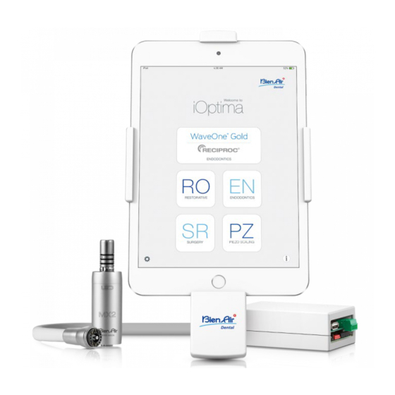
4 Description 4.1 System overview Electronically controlled integrated unit for dentistry allowing operation of multiple micromotors (MX2 and MX-i) with variable speed using the dental unit pedal. It is essential to connect an iPod touch® from 6 generation or an iPad mini® from generation using the lighting connector with the provided docking station. -
Page 12: Environmental Protection And Information For Disposal
Electric insulation class Class I per IEC 60601-1 (apparatus protected against electric shocks). Important: Consult the Instructions for Use of the following devices: Device Motor MX2 LED 2100199 1600677-001 Motor MX-i 2100245 1600755-001 Hose MX2 2100223 1600809-001 Hose MX-i 2100163 1600606-001 Control DMX3 set 2100278... -
Page 13: Installation
5 Installation ⚠ CAUTION Before use, please read these installation instructions and the iOptima operating instructions (2100279) carefully. Switch ON only when the system is ready for use. To conform with IEC 60601-1-2 standards, take into account the different routes of the wires through the unit (bend, fold, section etc) and only use the transformer provided with the kit (Refer to “5.3 DMX3 wiring”... -
Page 14: Dental Unit Pedal Connection
5.2 Dental unit pedal connection Connect either a pneumatic (0–3 bar / 0-43.5 psi) (1) or an electrical (0–5 Vdc) (2) dental unit pedal according to the following: FIG. 3 5.3 DMX3 wiring Note: Refer to the corresponding diagram on the following pages. ⚠... - Page 15 D. Fix the whiteboxes (1601015 and 1502569) to the dental unit using Velcros (1502565). E. Connect the pneumatic circuit (1502566) to the delivery unit and to the motors according to the “5.3.2 DMX3 with 1 MX2 motor diagram” on page 12. Note: Please use pneumatic pipes with an internal diameter of 2.8 mm (7/64").
-
Page 16: Dmx3 With 1 Mx2 Motor Diagram
5.3.2 DMX3 with 1 MX2 motor diagram... -
Page 17: Dmx3 With 2 Mx2 Motors Procedure
5.3.3 DMX3 with 2 MX2 motors procedure A. Drill a hole of diameter 12 mm (15/32") in the unit to install the Power supply reset switch (1502568). B. Connect together: Power supply reset switch (1502568), Power Supply PMP90 (1500666) (1) and Power Outlet Cable (1300067). FIG. - Page 18 I. Connect the dual motor whitebox (1502569) to the motor hoses following the color code on the connectors. Motor 1 shall be connected to (1.1), motor 2 shall be connected to (1.2). J. Connect the Power supply reset switch to the DMX3 Whitebox (1601015) (2). FIG.
-
Page 19: Dmx3 With 2 Mx2 Motors Diagram
5.3.4 DMX3 with 2 MX2 motors diagram... -
Page 20: Dmx3 With 1 Mx2 Motor And 1 Mx-I Motor Procedure
5.3.5 DMX3 with 1 MX2 motor and 1 MX-i motor procedure A. Drill a hole of diameter 12 mm (15/32") in the unit to install the Power supply reset switch (1502568). B. Connect together: Power supply reset switch (1502568), Power Supply PMP90 (1500666) (1) and Power Outlet Cable (1300067). - Page 21 I. Connect the dual motor whitebox (1502569) to the motor hoses following the color code on the connectors. MX2 Motor shall be connected to (1.1), MX-i motor shall be connected to (1.2). J. Connect the Power supply reset switch to the DMX3 Whitebox (1601015) (2). FIG.
- Page 22 L. Connect the DMX3 Whitebox (1601015) to the dual motor whitebox (1502569) with the DMS connection (1502525) (1). FIG. 27 M. Connect the USB Lightning cable (not provided in the set) to the DMX3 Whitebox (1601015). N. Drill a hole of diameter 19 mm (3/4") in the unit with the hole saw (3300409). Pass the USB Lightning cable through the opening on the dental unit.
-
Page 23: Dmx3 With 1 Mx2 Motor And 1 Mx-I Motor Diagram
5.3.6 DMX3 with 1 MX2 motor and 1 MX-i motor diagram... -
Page 24: Dmx3 With 1 Piezo Scaler
5.3.7 DMX3 with 1 Piezo Scaler procedure Note: The Piezo scaler is an add-on of the motor(s) and can only be set on holder 3. Refer to the corresponding procedure for the motor installation : • “5.3.1 DMX3 with 1 MX2 motor procedure” on page 10 •... -
Page 25: Dmx3 With 1 Piezo Scaler Diagram
5.3.8 DMX3 with 1 Piezo Scaler diagram... -
Page 26: Dmx3 With Peristaltic Pump On Piezo Scaler Output (Without Dms) Diagram
5.3.9 DMX3 with peristaltic pump on Piezo Scaler output (without DMS) diagram... -
Page 27: Dmx3 With 1 Piezo Scaler And Peristaltic Pump Diagram
5.3.10DMX3 with 1 Piezo Scaler and peristaltic pump diagram... -
Page 28: Dmx3 With 3 Motors Diagram
5.3.11DMX3 with 3 motors diagram... -
Page 29: Ioptima Application Settings
6 iOptima application settings 6.1 Display configuration A. When used with an iPad mini®, the app automatically displays accordingly to the orientation of the iPad. See CAUTION of the user IFU (REF 2100279), p.26. B. To correct the orientation of the display if it is incorrect (e.g. if you want to change the orientation of the iPad after the app has been launched), quit the app, reposition the iPad as desired and then restart the app according to the standard procedure (see user IFU, p.40). -
Page 30: Change Instrument
B. Tap Board configuration to display the Board configuration page. C. Select either No holder switch (1) or With holder switch tab (2) and set the instrument type for each holder. Note: The instrument in use displays a green border and check mark (3). FIG. -
Page 31: Configure Piezo Scaler
ware iOptima interface must be in V3.0.6 to support peristaltic pump. If required, software update is proposed when connecting iPod/iPad to the iOptima and launch- ing iOptima App V2.4.0 or higher. FIG. 33 6.2.2 Configure Piezo Scaler Note: Piezo Scaler can only be set on holder 3. A. -
Page 32: Lock Settings
6.3 Lock settings A. Tap Lock settings. input and confirm a passcode. Note: If Lock settings is activated, it is not possible to save any user-defined data! FIG. 35... -
Page 33: Integration Checklist
7 Integration Checklist Please go through the following checklist: • For use on iPad mini®, check that the screen’s rotation lock is disabled and make sure the screen displays the correct orientation according to its position (portrait or landscape orientation) A. -
Page 34: Maintenance
8 Maintenance 9.3 Terms of guarantee Bien-Air Dental SA grants the user a ⚠ guarantee covering all functional CAUTION defects, material or production faults. Use only original Bien-Air Dental SA maintenance products and parts. The The device is covered by this guarantee use of other products or parts could for: void the warranty. -
Page 35: References
The guarantee does not cover flexible iOptima set REF 1700705-001 “Optical fiber” type light conductors, or Designation any parts made of synthetic materials. The guarantee shall become null and 1502475-001 iOptima iDevice fixation void if the damage and its (1x) consequences are due to improper manipulation of the product, or 1600677-001 MX2 Micromotor (2x) -
Page 36: Optional Accessories (See Cover Page)
9.4.2 Optional accessories (see iOptima set REF 1700730-001 cover page) Designation Designation 1600809-001 MX2 Micromotor hose (1x) Mechanical interface iPod 1502568-001 Power supply reset switch 1502620-001 right mount 1500666-001 Power supply PMP90 (1x) Mechanical interface iPod 1502621-001 3P cable system, US/Asia, left mount 1300067-001 length 2.00 m (1x) - Page 37 REF 2100354-0004/2020.06 iOptima • © Bien-Air Dental SA...
- Page 38 Bien-Air Dental SA Länggasse 60 Case postale 2500 Bienne 6 Switzerland Tel. +41 (0)32 344 64 64 Fax +41 (0)32 344 64 91 dental@bienair.com Other adresses available at www.bienair.com REF 2100354-0004/2020.06 iOptima • © Bien-Air Dental SA...
Need help?
Do you have a question about the iOptima INT and is the answer not in the manual?
Questions and answers