
Related Manuals for Bien Air Lubricare 2 HIM-2


Summary of Contents for Bien Air Lubricare 2 HIM-2
- Page 1 Distributed by: Bien Air Dental SA Manufactured by: J.MORITA MFG. CORP. Dental Handpiece Maintenance Device Lubricare 2 INSTRUCTIONS FOR USE 2021-05-21 Pub. No.: K345-91001-503 (EN) Printed in Japan...
- Page 2 Before using the product, please read the In- Lesen Sie vor dem Gebrauch des Produkts Avant d’utiliser le produit, veuillez lire atten- structions for Use carefully. You can download die Bedienungsanleitung sorgfältig durch. tivement le mode d’emploi. Vous pouvez le it on the internet: Diese können Sie unter folgendem Link herun- télécharger sur Internet:...
- Page 3 Thank you for purchasing the Lubricare 2, dental handpiece maintenance device. For optimum safety and performance as well as to avoid causing harm to people, read this manual thoroughly before using the device and pay close attention to warnings and cautions. Keep this manual in a readily accessible place for quick and easy reference.
-
Page 4: Table Of Contents
Table of Contents 1 Accident Prevention ......................4 1.1 Customers ........................4 1.2 Dealers .......................... 4 1.3 Preventing Accidents ....................4 1.4 Disclaimers ........................4 1.5 In Case of Accident ....................... 5 2 Precautions .......................... 6 3 Intended Use and Usage Flow.................... 7 4 Components ......................... - Page 5 7.4 Other Maintenance Modes ..................29 7.4.1 Air Blow Mode ....................29 7.4.2 Flushing Mode ....................29 8 Cleaning the Device and Replacing Parts ............... 31 8.1 Daily Cleaning ......................31 8.1.1 Main Unit ......................31 8.1.2 Couplings ......................31 8.2 Regular Cleaning: Once a Month ................
-
Page 6: Accident Prevention
1 Accident Prevention 1.1 Customers Make sure to obtain clear instructions concerning the various ways to use this device described in this accompanying manual. Fill out and sign the warranty form and give the dealer from whom you purchased the device a copy. 1.2 Dealers Be sure to give clear instructions concerning the various ways to use this device described in this accompanying manual. -
Page 7: In Case Of Accident
1.5 In Case of Accident If an accident occurs, the Lubricare 2 must not be used until repairs have been completed by a qualified and trained technician authorized by the manufacturer. For customers who use the Lubricare 2 in the EU: If any serious incident occurs in relation to the device, report it to a competent authority of your country, as well as the manufacturer through your regional distributor. -
Page 8: Precautions
2 Precautions • Do not modify the device. • Do not place anything on top of the device. • Do not use the device near open flames or any place where it will be subjected to high temperatures. Doing so could cause the spray cans installed to catch fire or explode. •... -
Page 9: Intended Use And Usage Flow
3 Intended Use and Usage Flow █ Intended Use The Lubricare 2 is for lubricating and cleaning the inside of dental instruments. █ Usage Flow Maintenance Procedure Sterilization Cleaning Disinfection Cleaning* and Lubrication Inspection Packing Cleaning and Lubrication Handpieces can be lubricated using the Lubricare 2. •... -
Page 10: Components
4 Components █ Main Unit █ Accompanying Items (Parts of Device and Consumables) Oil Absorbent Pad Oil Absorbent Sheet Spray Stands (Qty: 1) (Qty: 1) (Qty: 2) Power Cord Air Tube Door Oil Absorbent Sheet (Qty: 1) (Qty: 1) (Qty: 1) * Cord type and plug shape depend on your country or region. -
Page 11: Parts Identification And Function
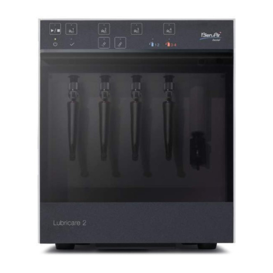
5 Parts Identification and Function 5.1 Parts Identification █ Front Side █ Front View Couplings (sold sepa- Operation Panel rately) Front Door Door Seal Chuck Lubri- cation Unit Oil Absorbent Sheet Oil Collection Tray Power Switch █ Bottom Side Door Hinge Exhaust Outlet Exhaust Opening Door Oil Absorbent... -
Page 12: Operation Panel: Name And Function Of Switches And Indicator Lamps
5.2 Operation Panel: Name and Function of Switches and Indicator Lamps █ Switches Start/Stop Switch Line Selection Switches Mode 1 Selection Switch Mode 2 Selection Switch Line Selection Switches Start/Stop Switch Press this switch to start or stop cleaning Select desired line(s) from Line 1 through or lubrication. - Page 13 █ Indicator Lamps Operation Lamp Line Selection Lamps Power Lamp Completion Lamp Lubrication Mode Selection Lamps Empty Spray Can Lamps Power Lamp Operation Lamp This lights up when the Power Switch is This lights up when handpiece lubrica- turned on. tion is in progress.
-
Page 14: Setup
6 Setup 6.1 Main Unit 6.1.1 Installation Install the main unit with at least the clearance shown below provided around the unit. █ Front View █ Top View More than 5 cm More than 5 cm • To prevent infection, always wear appropriate personal protective equipment such as surgical gloves, when using or cleaning the device. Then have the personal protective equipment disposed of appropriately. -
Page 15: Air Tube
6.1.2 Air Tube Example Air Regulator Air Valve (sold separately) Connect to main air valve 1. Open the rear cover (L). Rear Cover (L) Tube Joint 2. Pass the air tube through the tube hole and insert the tube into the tube joint firmly. -
Page 16: Power Cord
4. Pull up the adjustment dial of the air regulator and then rotate it to adjust the air pressure between 0.3 MPa and 0.5 MPa. * Recommendation: 0.4 MPa Increase Decrease Air Pressure • Set the input air pressure at 0.7 MPa or less. Otherwise, there is a risk of bursting the air tube. -
Page 17: Spray Cans
6.2 Spray Cans █ Spray Cans and Cleaning and Lubrication Lines Set the spray can “LUBRIFLUID” onto the spray stand for Lines 1 & 2 and the chuck lubrication unit. Set the spray can “SPRAYNET” onto the spray stand for Lines 3 & 4. •... -
Page 18: Spray Stands
6.2.1 Spray Stands █ Setting Rear Cover (R) 1. Open the rear cover (R). 2. Depending on a spray can’s volume, the correct orientation of the spray stand differs. Check the spray can volume and make sure the protrusion hub in the middle of the spray stand is correctly facing up or down, de- pending on the spray can as shown in the table below, and then set it straight down. -
Page 19: Spray Cans
6.2.2 Spray Cans █ Setting * Remove the cap and aerosol actuator from the spray can. Aerosol Actuator Inlet Port 1. Open the rear cover (R), and then insert the tip of the spray valve stem into the inlet port. •... -
Page 20: Spray Stand Adjustment
█ Removing 1. Turn the lock lever down in clockwise direction. 2. Check that the lock lever is horizontal, and then remove the spray can. * If the spray can is still connected to the inlet port, pull the can straight down. Lock Lever 6.2.3 Spray Stand Adjustment If the spray can is loose vertically even when the lock lever is properly... -
Page 21: Couplings
6.3 Couplings Right Wrong Couplings for the Lubricare cannot be used for the Lubricare 2. • For handpieces from other manufacturers, use the optional couplings designed specifi- cally for the Lubricare 2 or genuine couplings of your dental treatment unit. •... -
Page 22: Oil Absorbent Sheet
6.4 Oil Absorbent Sheet Set an oil absorbent sheet in the unit. Check that the longer direction is oriented towards the front side of the unit. * The sheet can be installed either way up. Shorter Length Longer Length Oil Absorbent Sheet Front Side 6.5 Oil Collection Tray and Oil Absorbent Pad Pull out the oil collection tray, set an oil absorbent pad into it, and then... -
Page 23: Door Oil Absorbent Sheet And Front Door Sheet Stopper
6.6 Door Oil Absorbent Sheet and Front Door Sheet Stopper 1. Insert the front door sheet stopper into the door oil absorbent sheet Front Door Sheet Stopper with the bumps on the front door sheet stopper aligned with the holes on the door oil absorbent sheet. Hole Hole Hole... -
Page 24: Usage
7 Usage 7.1 Operating, Transport and Storage Environments Operating Environments: Temperature: +10°C to +40°C (+50°F to +104°F) Humidity: 30% to 75% (without condensation) Atmospheric Pressure: 70 kPa to 106 kPa ■ Do not expose the device to direct sunlight for an extended period of time. ■... -
Page 25: Basic Operation
7.3 Basic Operation Be sure to check the following points before using the Lubricare 2. • Is the air pressure setting between 0.3 MPa and 0.5 MPa? (Recommendation: 0.4 MPa) • Does each coupling have proper O-rings? • Are all connection nuts for couplings properly secured? 7.3.1 Turning Power On/Off On the right side of the unit, turn the Power Switch on ( ). - Page 26 Starting Cleaning Mode 1 Mode 2 1. Press the desired Line Selection Switches for handpiece maintenance. The corresponding lamps will light up based on the selected lines. (Example: The illustration above shows that Mode 1 is selected for Line 3.) To cancel the line selection, press the Line Selection Switch again.
-
Page 27: Chuck Lubrication
Detaching Handpieces Check that the Completion Lamp is lit, and then open the front door. Completion Lamp Micromotor Attachments Release Button Hold the attachment with one hand, push the release button with the other, and pull the attachment out. Wipe excess oil from the handpiece with a soft cloth or gauze after the maintenance. -
Page 28: Handpiece Body Lubrication
7.3.4 Handpiece Body Lubrication The initial settings for lines 1 to 4 are set for Mode 1. Check the handpiece type and change the mode as neces- sary. p. 10 “5.2.1 Recommended Mode” p. 19 “6.3 Couplings” p. 28 “7.3.5 Switching Maintenance Mode” Attaching Handpieces Perform handpiece lubrication with the LUBRIFLUID can set onto the spray stand for Lines 1&... - Page 29 2. Press the Start/Stop Switch. The Line Selection Lamp for the current lubrication process will blink, and the lamps for the reserved lines will light up. Press the Start/Stop Switch again to stop the process. • Do not press the Start/Stop Switch after selecting a Line that the handpiece is not connected. Otherwise, oil mist might spray out into your eyes.
-
Page 30: Switching Maintenance Mode
7.3.5 Switching Maintenance Mode █ Mode 1/Mode2 Switching Procedures The initial settings for lines 1 to 4 are set for Mode 1. Check the handpiece type and select the most appropriate lubrication mode for each handpiece. p. 10 “5.2.1 Recommended Mode” 1. -
Page 31: Other Maintenance Modes
7.4 Other Maintenance Modes 7.4.1 Air Blow Mode Use Air Blow Mode to remove excess oil when performing lubrication for handpieces other than Bien-Air Dental SA products or after direct lubrication from a spray can. █ Procedures 1. Attach the handpiece and close the front door. Hold Down 2. - Page 32 █ Procedures 1. Attach the handpieces and close the front door. 2. Select the Line Selection Switches for the lines with the handpieces attached. Hold Down 3. Check that the selected lines are correct, and then hold down the Mode 2 Switch for two seconds. * The illustration above shows that Lines 1 through 3 are selected.
-
Page 33: Cleaning The Device And Replacing Parts
8 Cleaning the Device and Replacing Parts • To prevent infection, always wear appropriate personal protective equipment such as surgical gloves, when using or cleaning the device. • To prevent malfunction, be sure to turn the Power Switch off before performing the Lubricare 2 maintenance. * Order parts from your local dealer or Bien-Air Dental SA OFFICE. -
Page 34: Regular Cleaning: Once A Month
8.2 Regular Cleaning: Once a Month * Reinstall all parts after cleaning. 8.2.1 Front Door 1. Open the front door and pull straight it out. Hold the device firmly with one hand and pull the front door straight out with the other hand. -
Page 35: Parts Replacement
8.3 Parts Replacement p. 38 “10.3 Consumables” * Replace the parts as necessary depending on degree of wear and length of use. * Order parts from your local dealer or Bien-Air Dental SA OFFICE. 8.3.1 Oil Absorbent Sheet Remove the used oil absorbent sheet and replace it with a new one. Check that the sheet orientation is correct. -
Page 36: Nozzle Skirt
8.3.4 Nozzle Skirt Turn the power off. Pull out the nozzle skirt and replace it with a new one. Make sure it is oriented the right way up, as shown in the illustra- Nozzle Skirt tion. Pull Out Insert 8.3.5 Coupling O-rings 1. -
Page 37: Troubleshooting
9 Troubleshooting If the Lubricare 2 does not seem to be working properly, first inspect the locations described below. * If you cannot inspect the device yourself or if the device fails to work properly after being adjusted or after parts are re- placed, contact your local dealer or Bien-Air Dental SA OFFICE. - Page 38 Ref. Symptoms Possible Causes Remedies Page Oil mist is released. Handpiece shape Depending on the shape of the handpiece, it will p. 13 likely scatter more oil during the maintenance and Installation surfaces get will increase excess oil on the handpiece after the oily.
-
Page 39: Maintenance
10 Maintenance 10.1 Maintenance █ Regular Inspection The user (i.e., healthcare facility, clinic, hospital etc.) is responsible for the management, maintenance and use of medical devices. * The Lubricare 2 should be inspected every six months in accordance with the inspection items listed below. * Maintenance and inspection are generally considered to be the duty and obligation of the user, but if, for some reason, the user is unable to carry out those duties, the user may rely on qualified medical device service per- sonnel. -
Page 40: Consumables
10.3 Consumables Oil Absorbent Pads Oil Absorbent Sheets Door Oil Absorbent Sheets (Qty: 5) (Qty: 5) (Qty: 5) Code No.: 7373465 Code No.: 7376847 Code No.: 7376839 Nozzle Skirt (Qty: 1) Code No.: 7373791... -
Page 41: Technical Specifications
11 Technical Specifications 11.1 Specifications * Specifications and appearance are subject to change without notice due to improvements. Name Lubricare 2 Model HIM-2 Type Rating AC 100 V to 240 V, 50/60 Hz Power Consumption 10 VA to 25 VA Fuse 250 V 2 A slow blow and high breaking type 5 mm ×... -
Page 42: Intended User
11.2 Intended User a) Engaged person (people) in dental clinic b) Language Understanding: English or other languages offered in the Instruction for Use. Understanding of precautions and warnings. c) Experience: Not relevant... -
Page 43: Symbols
11.3 Symbols * Some symbols may not be used. Manufacturer Date of manufacture Serial number Unique device identifier Medical device GS1 DataMatrix “ON” (power) “OFF” (power) Standby Oil mark No open flame General warning sign Warning; Refer to instruction manu- Ventilation required Flammable material al/booklet... -
Page 44: Electromagnetic Disturbances (Emd)
12 Electromagnetic Disturbances (EMD) The Lubricare 2 (hereafter "this device") conforms to IEC 60601-1-2:2014 Ed. 4.0, the relevant international stan- dard for electromagnetic disturbances (EMD). The following is the “Guidance and Manufacturer's Declaration” which is required by IEC 60601-1-2:2014 Ed. 4.0, the relevant international standard for electromagnetic disturbances. - Page 45 Guidance and Manufacturer’s Declaration – Electromagnetic Immunity This device is intended for use in the electromagnetic environment specified below. The customer or the user of this device should assure that it is used in such an environment. Immunity Test IEC 60601 Test Level Compliance Level Electromagnetic Environment –...
- Page 46 Guidance and Manufacturer’s Declaration – Electromagnetic Immunity This device is intended for use in the electromagnetic environment specified below. The customer or the user of this device should assure that it is used in such an environment. Immunity Test IEC 60601 Test Level Compliance Level Electromagnetic Environment –...
- Page 47 █ Essential Performance None █ Cable Length Interface(s): Max. Cable Length, Shielding Cable Classification AC Power Cable 2.3 m (3-wire), Un-shielded AC Power Line...
- Page 52 Importer and Distributor Bien-Air Dental SA Bien-Air Italia s.r.l. Länggasse 60 Via Vaina 3 CH- 2500 Bienne 6 , Switzerland 20122 Milano, Italiy Tel. + 41 ( 0 ) 32 344 64 64 Tel. + 39 02 58 32 12 51 Fax + 41 ( 0 ) 32 344 64 91 Fax + 39 02 58 32 12 53 dental@bienair.com...
Need help?
Do you have a question about the Lubricare 2 HIM-2 and is the answer not in the manual?
Questions and answers