Table of Contents
Advertisement
Advertisement
Table of Contents

Related Manuals for Leadshine ELD2 Series


Summary of Contents for Leadshine ELD2 Series
- Page 1 User Manual for ELD2 Servo User Manual For ELD2 Servo www.leadshine.com 1 ...
- Page 2 User Manual for ELD2 Servo Introduction Thanks for purchasing Leadshine ELD2-series low-voltage AC servo drivers, this instruction manual provides knowledge and attention for using this driver. Contact tech@leadshine.com for more technical service . Incorrect operation may cause unexpected accident, please read this manual carefully before using product. We reserve the right to modify equipment and documentation without prior notice.
- Page 3 User Manual for ELD2 Servo Servo Driver: Must install in control cabinet with sufficient safeguarding grade. Must reserve sufficient gap with the other equipment. Must keep good cooling condition. Avoid dust, corrosive gas, conducting object, fluid and inflammable, explosive object from invading. Servo Motor: ...
- Page 4 User Manual for ELD2 Servo System selection Attention The rate torque of servo motor should be larger than effective continuous load torque. The ratio of load inertia and motor inertia should be smaller than recommended value. ...
-
Page 5: Table Of Contents
User Manual for ELD2 Servo Table of Contents Introduction ..............................2 Chapter 1 Introduction ............................ 7 1.1 Product Introduction .......................... 7 1.2 Inspection of product ......................... 8 Chapter 2 Installation ............................9 2.1 Storage and Installation Circumstance ....................9 2.2 Servo Driver Installation ........................9 2.2.1 Installation Method ......................... - Page 6 User Manual for ELD2 Servo 7.1.2 Installation wiring ......................... 59 7.2 Parameter ............................61 7.2.1 8th sort parameters specification ..................61 7.2.2 9th sort parameters specification ..................63 7.3 IO Operation mode .......................... 64 7.3.1 Homing ..........................64 7.3.2 Trigger path .......................... 66 7.3.3 Position limit, JOG and E-stop function................68 7.4 Communication control mode ......................
-
Page 7: Chapter 1 Introduction
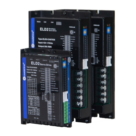
User Manual for ELD2 Servo Chapter 1 Introduction 1.1 Product Introduction ELD2 low-voltage AC servo is a special motion control product designed for machines and applications that request a best balance between outstanding and reasonable cost. Combined with abundant features like MFC, vibration suppression,Multi-mode filter function etc. It provide machines a compact size, low tuning works, but high resolution encoder up to 5000 lines, an unique servo system. -
Page 8: Inspection Of Product
Low‐voltage AC servo drive ( 24‐60VDC) b. Servo motor type The ELD2 series AC servo driver can be matched with a variety of domestic and foreign servo motor. Matched Motors... -
Page 9: Chapter 2 Installation
User Manual for ELD2 Servo Chapter 2 Installation 2.1 Storage and Installation Circumstance Table 2.1 Servo Driver, Servo Motor Storage Circumstance Requirement Item ELD2 series driver ELDM low voltage servo motor Temperature -20-80℃ -25-70℃ Humility Under 90%RH (free from condensation) Under 80%RH(free from condensation) Atmospheric Indoor(no exposure)no corrosive gas or Indoor(no exposure)no corrosive gas or... -
Page 10: Installation Space
User Manual for ELD2 Servo 2.2.2 Installation Space Reserve enough surrounding space for effective cooling. Figure 2.2 Installation Space for Single Driver Figure 2.3 Installation Space for several Drivers 2.3 Servo Motor Installation Notice Don’t hold the product by the cable, motor shaft or encoder while transporting it. No knocking motor shaft or encoders, prevent motor by vibration or shock. ... -
Page 11: Chapter 3 Wiring
User Manual for ELD2 Servo Chapter 3 Wiring Warning The workers of participation in wiring or checking must possess sufficient ability do this job. The wiring and check must be going with power off after five minutes. Caution Ground the earth terminal of the motor and driver without fail. ... -
Page 12: Position Control Mode
User Manual for ELD2 Servo 3.1.2 Position Control Mode DC Power supply Pulse 270Ω signal 270Ω SERVO ON COM_IN 4.7K 4.7K 24Vdc 4.7K 12~24Vdc 4.7K 4.7K HOME COM_OUT 4.7K CTRG RS485*2 4.7K ALM+ Commucation ALM- Port RS232 Figure 3‐1 Positional Control Mode Wiring Attention: 1、Only support 5V pulse and direction signal , 24V pulse signal suggest connect 2 KΩ resistance ... -
Page 13: Driver Terminals Function
User Manual for ELD2 Servo Pulse Input Interface Single Terminal Drive Mode 3.2 Driver Terminals Function 3.2.1 Control Signal Port-CN1 Terminal The left on Figure 3.3 is control signal port CN1 of servo driver with Molex-20 connector; Table 3.1 Signal Explanation of Control Signal Port‐CN1 CN1 Pin Signal IO Detail Positive differential pulse input,5V, DI1+ Input 500KHz... -
Page 14: Encoder Input Port-Cn2 Terminal
User Manual for ELD2 Servo Digital input signal 9, default value is Path1 select Input signal in position mode , low level available in default , max voltage is 24V input 20KHz Positive differential output1,24V, Default DO1+ Output 100mA Alarm output DO1- Output Negative differential output1,24V Positive differential output1,24V,... -
Page 15: Power Port
User Manual for ELD2 Servo 3.2.4 Power Port Table 3.5 Main Power Input Port‐CN4 Pin Signal Detail CN4 Power (+24~+48V) Pin Signal Detail CN3 Motor 3.2.5 Bus connector Cn8 Pin Signal Detail RS485+ 485data+ RS485- 485 data- 485GND 485 GND other Cn9 Pin Signal Detail RS485+ 485data+ RS485-... -
Page 16: I/O Interface Principle
User Manual for ELD2 Servo SW3: 485 terminal resistance,effect right now, support all modes SW3=off,disconnect the terminal resistance SW3=on,connect the terminal resistance SW4:Rotation direction,effect after power off and restart SW4=off,CCW SW4=on,CW 3.3 I/O Interface Principle 3.3.1 Switch Input Interface Figure 3‐4 Switch Input Interface ⑴ The user provide power supply, DC 12-24V, current≥100mA ⑵... -
Page 17: Pulse Input Interface
User Manual for ELD2 Servo 3.3.3 Pulse Input Interface Figure 3‐6 Pulse Input Interface Differential Drive Mode Figure3‐7 Pulse Input Interface Single Terminal Drive Mode (1) In order to transmit pulse data properly , we recommend using the differential drive mode. (2) The differential drive mode, AM26LS31, MC3487 or similar RS422 line drive. (3) Using of single-ended drive will cause reduction of the operation frequency. (4) The user provide external power supply for single-ended drive. -
Page 18: Analog Value Input Interface
User Manual for ELD2 Servo >4μs >5μs >4μs >5μs <0.2μs <0.3μs <0.2μs <0.3μs >1μs >2.5μs Figure 3.8 pulse + direction input interface timing (the maximum of pulse frequency : 500KHZ) 3.3.4 Analog Value Input Interface Figure 3‐9 Analog Input Interface 3.3.5 Servo Motor Encoder Input Interface Figure 3‐11 Servo Motor optical‐electrical Encoder Input Interface 18 ... -
Page 19: Chapter 4 Parameter
User Manual for ELD2 Servo Chapter 4 Parameter 4.1 Parameter List Mode Parameter Number Name P S T Classify Number 【Class 0】 P S T Model following control Basic control mode setup setting P S T real-time auto-gain tuning P S T ... - Page 20 User Manual for ELD2 Servo S Speed command rotational direction selection Speed, Torque S T Speed command input gain Control S Speed command reversal input S 1st speed setup S 2nd speed setup S ...
-
Page 21: Parameter Function
Encoder selection 4.2 Parameter Function Here is the explanation of parameters, you can check them or modify the value using software Protuner or the front panel of driver. Contact tech@leadshine.com if you need more technical service . 【 】 4.2.1 Class 0 Basic Setting Related... - Page 22 User Manual for ELD2 Servo Related Range unit default Pr0.01* Control Mode Setup control mode 20-28 Set using control mode Content When you set up the combination mode of 3.4.5, you Setup value 1st mode 2nd mode can select either the 1st or the 2nd with control mode Position switching input(C-MODE).
- Page 23 User Manual for ELD2 Servo You can set up the ratio of the load inertia against the rotor(of the motor)inertia. Pr0.04=( load inertia/rotate inertia)×100% Notice: If the inertia ratio is correctly set, the setup unit of Pr1.01 and Pr1.06 becomes (Hz). When the inertia ratio of Pr0.04 is larger than the actual value, the setup unit of the velocity loop gain becomes larger, Related Range unit...
-
Page 24: Class 1】Gain Adjust
User Manual for ELD2 Servo 1-32767 1-32767 Related Output pulse counts per one motor Range unit default Pr0.11* control mode revolution 1-2500 2500 Set the numerator of division/multiplication operation made according to the command pulse input. Related Range unit default Pr5.03* ... - Page 25 User Manual for ELD2 Servo 0 -30000 0.1/s You can determine the response of the positional control system. Higher the gain of position loop you set, faster the positioning time you can obtain. Note that too high setup may cause oscillation. Related Range unit default...
- Page 26 User Manual for ELD2 Servo 0 -2500 0.01ms Position loop, velocity loop, velocity detection filter, torque command filter have their 2 pairs of gain or time constant(1st and 2nd). Related Range unit default Velocity feed forward gain Pr1.10 control mode 0 -1000 0.1% Multiply the velocity control command calculated according to the internal positional command by the ratio of this parameter and add the result to the speed command resulting from the positional control process.
- Page 27 User Manual for ELD2 Servo during delay time with the 2nd gain. reserve reserve Valid for position and speed controls. Speed command is large Shift to the 2nd gain when the absolute value of the speed command exceeded (level + hysteresis)[r/min]previously with the 1st gain.
-
Page 28: Class 2】Vibration Suppression
User Manual for ELD2 Servo 0.1ms 0 -10000 For position controlling: if the difference between 1st gain and 2nd gain is large, the increasing rate of position loop gain can be limited by this parameter. <Position gain switching time> Notice: when using position control, position loop gain rapidly changes, causing torque change and vibration. -
Page 29: Class 3】Velocity/ Torque Control
User Manual for ELD2 Servo Set the depth of notch at the center frequency of the 1st notch filter. Notice: Higher the setup, shallower the notch depth and smaller the phase delay you can obtain. Related Range unit default 2nd notch frequency control mode Pr2.04 ... - Page 30 User Manual for ELD2 Servo The default setting of ELD2 hardware can,t support velocity mode or Torque mode , pls contact tech@leadshine.com for more details . Related Range unit default Speed setup, Internal /External Pr3.00 control mode switching ‐ 0 ‐3 0 S ...
- Page 31 User Manual for ELD2 Servo 2. When you compose a position loop outside of the driver while you use the driver in velocity control mode, the setup of Pr3.02 gives larger variance to the overall servo system. 3. Pay an extra attention to oscillation caused by larger setup of Pr3.02. ...
- Page 32 User Manual for ELD2 Servo Set the time required for the speed command(stepwise input)to reach 1000r/min to Pr3.12 Acceleration time setup. Also set the time required for the speed command to reach from 1000r/min to 0 r/min, to Pr3.13 Deceleration time setup. Assuming that the target value of the speed command is Vc(r/min), the time required for acceleration/deceleration can be computed from the formula shown below.
- Page 33 User Manual for ELD2 Servo 0 ‐1 ‐ 0 T Select the direction positive/negative direction of torque command Setup value designation Specify the direction with the sign of torque command Torque command input[+] positive direction, [-] negative direction Specify the direction with torque command sign(TC-SIGN). OFF: positive direction ON: negative direction Related Range...
- Page 34 User Manual for ELD2 Servo Related Range unit default Pr4.04* Input selection DI5 control mode ‐ 0‐00FFFFFFh 00000007h P S T Related Range unit default Pr4.05* Input selection DI6 control mode 0‐00FFFFFFh ‐ P S T Related Range unit Pr4.06* Input selection DI7 control mode ‐ 0‐00FFFFFFh P ...
- Page 35 User Manual for ELD2 Servo Related Range unit default control mode Pr4.11* Output selection DO2 00020202h 0‐00FFFFFFh P S T ‐ (131586) Related Range unit default control mode Pr4.12* Output selection DO3 00000704h 0‐00FFFFFFh P S T ‐ (65793) Related Range unit default control mode Pr4.13* Output selection DO4 00000303h ...
- Page 36 User Manual for ELD2 Servo maintained until Pr4.33 INP hold time has elapsed. After the hold time, INP output will be turned ON/OFF according to the coming positional command or condition of the positional deviation. Related Range unit default INP hold time control mode Pr4.33 ...
- Page 37 User Manual for ELD2 Servo Speed coincidence output ON -> OFF timing (Pr4.35 +10) r/min Related Range unit default At-speed(Speed arrival) Pr4.36 control mode r/min 10-20000 1000 S Set the detection timing of the speed arrival output (AT-SPEED). When the motor speed exceeds this setup value, the speed arrive output (AT-SPEED) is output. Detection is associated with 10r/min hysteresis .
- Page 38 User Manual for ELD2 Servo Mechanical brake start delay time setup, mainly used to prevent servo off “galloping “phenomenon. Set up time from when detecting the off of servo-on input signal(SRV-ON)is to when external brake release signal(BRK-OFF)turns off, while the motor turns to servo off during the motor in motion. ...
- Page 39 User Manual for ELD2 Servo You can select whether or not to activate Err0d.0 (main power under‐voltage protection)function while the main shutoff continues for the setup of Pr5.09(The main power‐OFF detection time). Setup value Action of main power low voltage protection When the main power is shut off during Servo-On,Err0d.0 will not be triggered and the driver turns to Servo-OFF. The driver returns to Servo-On again after the main power resumption.
-
Page 40: Class 6】Special Setup
User Manual for ELD2 Servo communication You can set up the communication speed of RS485. Set value Baud rate Set value Baud rate 2400bps 38400bps 4800bps 57600bps 9600bps 115200bps 19200bps Baud rate error is 2400-38400bps±5% ,57600-115200bps±2% Related Range unit default Axis address Pr5.31* control mode 0-127 During communication with the host (e.g. PC) to control multiple shafts, the shaft being accessed by the host should be identified. - Page 41 User Manual for ELD2 Servo Related Range unit default Trial run cycle times control mode Pr6.22 0-32767 The cycling times of JOG run(position control) 41 ...
-
Page 42: Chapter 5 Alarm And Processing
User Manual for ELD2 Servo Chapter 5 Alarm and Processing 5.1 Alarm List Protection function is activated when an error occurs, the driver will stop the rotation of servo motor, and the protuner software will automatically display the corresponding fault error code. The history of the error can be viewed on data monitoring mode. -
Page 43: Alarm Processing Method
User Manual for ELD2 Servo Excessive vibration ● ● ● Over-speed 1 ● ● ● Motor speed out of control Electronic gear ratio error I/F input interface allocation error ● ● I/F input interface function set error ● ... - Page 44 User Manual for ELD2 Servo Driver inner fault replace the driver with a new one Main Extra Display: “ ” Error code Content: DC bus circuit error Cause Confirmation Solution Vdc/GND under-voltage Check the voltage of Vdc/GND Make sure voltage of Vdc/GND in terminal proper range Driver inner fault replace the driver with a new one ...
- Page 45 User Manual for ELD2 Servo Cut off driver output wiring, make Short of IGBT module srv_on available and drive motor, replace the driver with a new one check whether over-current exists abnormal setting of control Modify the parameter Adjust parameter to proper range parameter Check control command whether abnormal setting of control Adjust control command: open...
- Page 46 User Manual for ELD2 Servo Power line UVW connection error Check connection of UVW connection error Over current Use another driver with higher rated Over current power Main Extra Display: “ ” Error code Content: Resistance discharge circuit over‐load Cause Confirmation Solution Regenerative energy has Check the speed if it is too lower motor rotational speed;...
- Page 47 User Manual for ELD2 Servo Encoder measuring replace the driver with a new one circuit damaged Extr Main Display: “ ” Error code Content: Multiple turn absolute value encoder battery error Cause Confirmation Solution Check the battery Replace battery Encoder battery error Check the motor Replace motor Reset the driver alarm...
- Page 48 User Manual for ELD2 Servo code Content: excessive vibration Cause Confirmation Solution Current vibration Current vibration Cut down the value of Pr003. Pr004 Stiffness is too strong Stiffness is too strong Main Extra Display: “ ” Error code Content: over‐speed 1 Cause Confirmation Solution ...
- Page 49 User Manual for ELD2 Servo if it is proper or not correctly Main Extra Display: “ ” Error code Content: I/F input interface function set error Cause Confirmation Solution Signal allocation error Check the value of PA_400, PA_401, Assure the value of PA_400, PA_402,PA_403,PA_404 if it is proper PA_401, PA_402, PA_403, PA_404 or not...
- Page 50 User Manual for ELD2 Servo Cause Confirmation Solution Forced-alarm input signal Check forced-alarm input signal Assure input signal wiring correctly has been conducted Main Extra Display: “ ” Error code Content: Motor code error Cause Confirmation Solution Motor code error Motor code error Set Pr7.15 correctly ...
-
Page 51: Chapter 6 Trial Run
If drive alarm occurs, the cause of alarm should be excluded and Svon signal must be invalid before restarting the driver. Please don’t touch terminal strip or separate the wiring. Note: there are two kinds of trial run : trial run without load and trial run with load . The user need to test the driver without load for safety first. Contact tech@leadshine.com for more technical service . 6.1 Inspection Before trial Run 6.1.1 Inspection on wiring Table 7.1 Inspection Item Before Run No Item ... -
Page 52: Timing Chart On Power-Up
User Manual for ELD2 Servo 6.1.2 Timing chart on power-up <0.5 second r,t control power inner control power >0 millisecond R,S,T main power <0.8 second BUS voltage <1.5 second Servo ready >0 millisecond Servo on input <10 millisecond Dynamic brake <0.15 second Motor power on <10 millisecond BRK-OFF >0.1 second... -
Page 53: Trial Run
User Manual for ELD2 Servo 24VDC , and it is forbidden to connect these signal directly for the power of 24VDC , it will destroy the hardware of servo driver. 6.2 Trial Run After installation and connection is completed , check the following items before turning on the power: Wiring ? (especially power input and motor output) ... -
Page 54: Torque Control
User Manual for ELD2 Servo tech@leadshine.com for more details . Notice : You must do inspection before velocity control test run. Table 7.5 Parameter Setup of Velocity Control No Parameter Name input Setup value Unit Control mode setup PA_001 PA_312 Acceleration time setup User-specified millisecond Deceleration time setup millisecond PA_313 User-specified Sigmoid acceleration/deceleration time millisecond PA_314 User-specified setup... -
Page 55: Automatic Control Mode Run
User Manual for ELD2 Servo PA_312 Acceleration time setup User-specified millisecond Deceleration time setup millisecond PA_313 User-specified Sigmoid acceleration/deceleration time millisecond PA_314 User-specified setup PA_315 Zero-clamp function selection PA_319 Torque command direction input gain User-specified 0.1V/100% PA_320 Torque setup input reversal User-specified Speed limit value 1 R/min PA_321 User-specified... -
Page 56: Position Mode
User Manual for ELD2 Servo torque mode The step of changing the operation mode: 1, Switch the driver to Servo Off status. 2, Modify the corresponding parameters of control mode to EEPROM. Turn off/on the power to make the new mode works after setup completed. 6.3.2 Position Mode The driver is widely used for precise positioning in position control mode. - Page 57 User Manual for ELD2 Servo multiplying factor and applies the result to the position control section as the positional command. By using this function, desired motor rotations or movement distance per unit input command pulse can be set. Table 7.9 Parameter Setup of Electronic Gear Ratio No Parameter Name Setup method PA_009 First command frequency double molecular PA_010...
- Page 58 User Manual for ELD2 Servo No Parameter Name Setup method PA_518 Command pulse prohibit input invalid setup Please refer to chapter 4 PA_519 Command pulse prohibit input read setup And the input port should be assigned for “INH”, for details of these parameters, refer to PA_400 – PA409. ...
-
Page 59: Chapter 7 Pr Function
User Manual for ELD2 Servo Chapter 7 PR function 7.1 Overview PR is uniaxial motion control function which is controlled by procedure software. Mainly uniaxial motion command control, save the motion control function of the controller. Servo Motion Driver controller / PLC Pulse+Direction positioning General positioning motion control system Homing, JOG Position... -
Page 60: Installation Wiring
User Manual for ELD2 Servo Positive point move Negative point move JOG speed and acceleration selectable Protect device by limiting move range Position limit Positive and negative signal input by IO Software position limit setting Position limit deceleration settable Remark:Software position limit effective after homing accomplish. Input E-stop signal through I/O,stop positioning operation. - Page 61 User Manual for ELD2 Servo Forward limit Reverse limit Home signal Path ADD0 address 0 Path ADD1 address 1 Path ADD2 address 2 Path ADD3 address 3 Torque TC-SEL switch Remark:CMD_OK means PR instruction is sent,maybe motor is not yet in place. MC_OK means PR instruction is sent and motor is in place. CTRG、HOME is edge trigging, but effective level need to last more than 1ms.
-
Page 62: 8Th Sort Parameters Specification
User Manual for ELD2 Servo 7.2 Parameter PR parameters contain 8th and 9th parameters, 8th parameters is e-stop and control parameters, 9th parameters is store path table. 7.2.1 8th sort parameters specification Name Data Range Default Value Definition PR 's global control function Bit0:CTRG rising edge trigger / double edge trigger, 0/1 PR control P8.0 Bit1:Software limit effectively,0 invalid /1 valid... - Page 63 User Manual for ELD2 Servo Homing P8.17 1-32767 Homing acceleration acceleration Homing P8.18 1-32767 Homing deceleration deceleration P8.19 Reserved P8.20 Reserved P8.21 Reserved Position limit P8.22 1-32767 E-stop deceleration, when the limit is encountered e-stop speed e-stop P8.23 1-32767 E-stop speed, when the STOP signal is encountered speed P8.24 Reserved...
-
Page 64: 9Th Sort Parameters Specification
User Manual for ELD2 Servo 7.2.2 9th sort parameters specification Default Data Name Range Definition value type PR path mode, determine the action according to type property Bit0-3: TYPE , 0 No Action /1 location positioning /2 speed running /3 homing, use P/V/H to express Bit4:INS,0 do no interrupt / 1 interrupt, Use !... -
Page 65: Io Operation Mode
User Manual for ELD2 Servo PR1 position H (+-2^ The position parameter of the path, refer to PR motion P9.1 type for specific meaning. PR1 position L P9.2 Position parameter low 16bit The position parameter of the path, refer to PR motion 0+-60 P9.3 PR1 speed type for specific meaning. - Page 66 User Manual for ELD2 Servo Parameter Name Specification PR 's global control function Bit0:CTRG Rising edge trigger / Double edge trigger ,0/1 control setting P8.00 Bit1: software limit is valid,0 invalid/1 valid Bit2:homing after power on,0 invalid/1 valid Bit0:Homing direction,0 reverse/1 forward Bit1: whether move to specific position after homing, 0 No/1 Yes Bit2-7:Homing mode =0,Position limit homing =1,Zero point homing...
-
Page 67: Trigger Path
User Manual for ELD2 Servo : Remark Homing also be done by positioning function, only need to set the path to be homing mode. , after the signal effective, CMD_OK and MC_OK Both of them can be used to represent action is complete there will have a delay within 1 ms. 7.3.2 Trigger path Positioning path can make single segment running, also can make continuous running, configurable. - Page 68 User Manual for ELD2 Servo Position P901 for high 16bit,P902 for low 16bit. P901-P902 Speed running speed, rpm P903 Acceleration time Unit: ms/1000rpm P904 Deceleration time Unit: ms/1000rpm P905 Pause time Pause time after Instruction stop P906 Special Parameters Path 0 mapped to Pr8.02 directly P907 Each path occupy eight parameters and so on And so on...
-
Page 69: Position Limit, Jog And E-Stop Function
User Manual for ELD2 Servo Interrupt function can be understood as a path's priority. Interrupt valid path, can suspend or drop current path under the trigger, run the path directly. Similar to the interrupt priority level of functions. To set it in the path set parameters. 7.3.3 Position limit, JOG and E-stop function. -
Page 70: Communication Control Mode
User Manual for ELD2 Servo 1.JOG Manual point move function 2.Position limit and E-stop, apply to safe stop and so on condition 7.4 Communication control mode Communication control mode can realize same function as IO operation, Can flexible modify parameters and trigger action to run, can control more than one operation by field bus, save the wiring and good flexibility. - Page 71 User Manual for ELD2 Servo Setting Setting Baud rate Baud rate value value 2400bps 38400bps Communication band 4800bps 57600bps Pr5.30 rate 9600bps 115200bps 19200bps Baud rate deviation is 2400~38400bps±5%, 57600~115200bps±2% Modbus sub-station address number(Slave ID) . Device No. Pr5.31 (16bit,485 address..0x6002) Write 0x01P,P section positioning Write 0x020,homing Write 0x021,The current location manually set to zero.
- Page 72 User Manual for ELD2 Servo r/min 0x6203 Pr9.03 PR0 speed ms/Krpm 0x6204 Pr9.04 PR0 acceleration ms/Krpm 0x6205 Pr9.05 PR0 deceleration 0x6206 Pr9.06 PR0 pause time 0x6207 Pr9.07 PR0 trigger 0x6208~0x620f Pr9.08~Pr9.15 PR1 parameters The same with Pr9.00~Pr9.07 0x6210~0x6217 Pr9.16~Pr9.23 PR2 parameters The same with Pr9.00~Pr9.07 0x6218~0x621f Pr9.24~Pr9.31 PR3 parameters...
-
Page 73: 485 Communication Installation Wiring
User Manual for ELD2 Servo 7.4.2 485 communication Installation wiring Bus connector Cn8 Pin Signal Detail RS485+ 485data+ RS485- 485 data- 485GND 485 GND other Cn9 Pin Signal Detail RS485+ 485data+ RS485- 485 data- 485GND 485 GND other Do not use CN3 communication port,that is for parameters setting only 7.4.3 Fixed trigger mode Fixed trigger mode is to config no more than 16 segments homing and path. -
Page 74: Immediately Trigger Method
User Manual for ELD2 Servo Acceleration time Unit: ms/1000rpm P904 Deceleration time Unit: ms/1000rpm P905 Pause time Pause time after Instruction stop P906 Special Parameters Path 0 mapped to Pr8.02 directly,Other reserved P907 And so on Each path occupy eight parameters and so on Set path 1~ path15 as same as path0 . -
Page 75: Test Pr-Mode With Serial Debugging Assistant
User Manual for ELD2 Servo Please refer to parameter specification for specific data setting. 7.4.5 Test Pr-Mode with Serial debugging assistant Disconnect and close the debugging software,Test PR mode with Serial debugging assistant software Pr-Mode communication trigger function description 7.4.5.1 Fixed trigger mode Fixed trigger mode is to config no more than 16 segments homing and path. Then, replace CTRG and HOME with Pr8.02(trigger register) to start the operation path. - Page 76 User Manual for ELD2 Servo Mode XXXX P9.00 10-11 High position XXXX P9.01 Low position XXXX 12-13 P9.02 Speed XXXX 14-15 P9.03 Acceleration XXXX 16-17 P9.04 Deceleration XXXX 18-19 P9.05 Delay time XXXX 20-21 P9.06 Trigger control 0x0010 22-23 P9.07 Check code Open the serial debugging software Set the correct communication format, the baud rate must be 19200, even parity check.
- Page 77 User Manual for ELD2 Servo Actually Hi Hi Data 5 written quantity NUM1 NUM data Lo Lo Word 6 quantity Lo Data quantity 7 NUM2 CRC 2 X NUM1 check code Hi Byte 8 Hi DATA1 DATA1 9 Lo 10 Hi ...
- Page 78 User Manual for ELD2 Servo Send Recieve Slave ID Slave ID 1 ID 0~31 0~31 Function Function 2 FC 0x06 FC 0x06 3 Hi Hi ADDR Address ADDR Address 4 Lo Lo Actually 5 Hi Hi Data DATA DATA ...
-
Page 79: Upper Computer Operation
User Manual for ELD2 Servo positioning related data of path-0) 17 4D the CRC verification code, do not have to directly input, click the corresponding send area verification button automatically generated The final analysis is as follows: speed is 1000r/min, acceleration and deceleration time is 100ms, Speed mode 7.5 Upper computer operation Upper computer is used for drive parameter setting and save, steps for debugging is:... -
Page 80: Rs485 Parameter Address
User Manual for ELD2 Servo _END means that path is E-stop. 5.Test run After confirming that the parameters are set correctly, the test begins. The interface is shown below Click the number marked red in the figure and click start to run according to the speed in the path parameter configuration diagram. - Page 81 User Manual for ELD2 Servo Status monitoring Sort Name Address Operation Unit Specification status U phase current 0x187 0.1A monitoring V phase current 0x188 0.1A Status monitoring 0x191 Refer to pointer 1 specification2 Status monitoring 0x192 pointer 2 Status monitoring 0x193 pointer 3 Status monitoring 0x194 pointer 4 Virtue input 1...
- Page 82 Position error clear =1:valid ;=0:invalid Command pulse input is INH =1:valid ;=0:invalid Reserved Reserved [10] Reserved [11] Electronic gear selection 1 DIV1 =1:valid ;=0:invalid [12] Electronic gear selection 2 DIV2 =1:valid ;=0:invalid [13] Internal instruction speed choice INTSPD1 =1:valid ;=0:invalid www.leadshine.com...
- Page 83 Velocity Matching VCOIN =1:valid ;=0:invalid Reserved Reserved Position command have output or PCMD =1:valid ;=0:invalid [10] Reserved [11] Reserved [12] Reserved [13] Speed command have output or VCMD =1:valid ;=0:invalid [14] alarm signal ALARM =1:valid ;=0:invalid [15] Reserved Reserved www.leadshine.com...
- Page 84 Auxiliary function as below. Address Control word Auxiliary function 0x4444 Download default parameters(Except the motor parameters) 0x19A 0x5555 Save parameters 0x7777 Remove the alarm ( can only clear purgeable alarm) 0x7788 Clear historical alarm Address Control word Specification 0x1F7 0x5555 others null www.leadshine.com...
-
Page 85: Chapter 8 Product Specification
User Manual for ELD2 Servo Chapter 8 Product Specification Notice Servo driver must be matched with relevant servo motor, Contact tech@leadshine.com if you need more technical service. 8.1 Driver Technical Specification Table 8.1 Driver Specification Type ELD2-RS400 Rated output power 400W Rated output current Max output current Main power 24-60VDC... -
Page 86: Accessory Selection
Download new value of parameters to the driver and save it, and restart the driver to make the new value available. Refer to “ Quick Reference Of ELD2 series Servo Product.pdf ” for details about tuning the servo . Notice:Please contact tech@leadshine.com for technical service for 3 party motor . ... -
Page 87: Contact Us
Tel: 86-755-2641-8447 86-755-2641-8774 (for Asia, Australia, Africa areas) 86-755-2665-5136 (for America areas) 86-755-8654-2465 (for Europe areas) Fax: 86-755-2640-2718 tech@leadshine.com (for All) Email: Sales Hot Line Tel: 86-755-2641-7674 (for Asia, Australia, Africa areas) 86-755-2640-9254 (for Europe areas) 86-755-2641-7617 (for America areas) sales@leadshine.com...
Need help?
Do you have a question about the ELD2 Series and is the answer not in the manual?
Questions and answers