
Subscribe to Our Youtube Channel
Related Manuals for Leadshine SMC6480


Summary of Contents for Leadshine SMC6480
- Page 1 Authorized Distributor of Leadshine Technology Hardware Installation Manual SMC6480, SMC6490 and PMC6496 www.leadshine.com HWMN-SMC6-R20120417 雷赛智能官方代理:雷创智能科技 www.leadtronker.com...
- Page 2 Authorized Distributor of Leadshine Technology Leadshine reserves the right to make changes without further notice to any products herein to improve reliability, function or design. Leadshine does not assume any liability arising out of the application or use of any product or circuit described herein;...
- Page 3 The person who setups the controller should have a Notice better understanding on electronics and mechanics. Contact Leadshine technical guys when you have questions on this document. Before running execute motion program, make sure the axes will not impact anything.
-
Page 4: Table Of Contents
2.1.5. Serial Port COM1..........................8 2.1.6. Serial Port COM2..........................9 2.1.7. Power-up level DIP Switch Function ....................9 2.1.8. E-Stop Connector (SMC6480) ......................10 2.1.9. D/A Output Connector (SMC6480)..................... 10 2.1.10. Encoder Connector(SMC6490 and PMC6496)................. 10 2.1.11. Manual Pulse Connector (SMC6490 and PMC6496)................ 11 2.3 Isolated and Non-isolated Power Output...................... - Page 5 4.3 Proximity Sensor Connection.......................... 24 4.4 Photoelectric Sensor Connection........................25 4.5 Relay Connections............................25 4.6 Connection Troubleshooting ........................... 26 Chapter 5 Mechanical Specifications ..........................27 5.1 Mechanical Specification of SMC6480......................27 5.1 Mechanical Specification of SMC6490 and SMC64596................. 27 Contact Us..................................28 HWMN-SMC6-R20120417 雷赛智能官方代理:雷创智能科技...
-
Page 6: Family Overview
Chapter 1 Family Overview 1.1 Introduction Leadshine SMC6000 is 10/100M Ethernet-based general purpose motion controller. It provides 1 to 4 axes motion control to stepper/servo motors for various operations. It can work in standalone mode without PC or work as a slaver in an Ethernet network. -
Page 7: Product Covered
Hardware Installation Manual 1.2 Product Covered This manual tries to specify the functionality, structure, connector pin assignment and connections of Leadshine SMC6480, SMC6490 and PMC6496. Table 1-1 illustrates the key features of Leadhine SMC600. Table 1-1 SMC6000 Motion Controller Specifications... -
Page 8: Order Information
Authorized Distributor of Leadshine Technology SMC6000 Series Motion Controller Hardware Installation Manual 1.4 Order Information Table 1-2 Order Information Part Number Description SMC6480 Motion Controller SMC6480, BASIC SMC6480G Motion Controller SMC6480, G-Code SMC6490-FM Motion Controller SMC6490, BASIC, Ferroelectric Memory... -
Page 9: Controller Interface And Pin Assignment
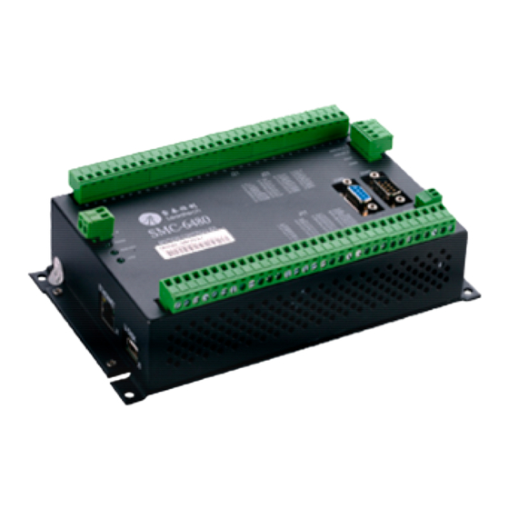
2.1 Controller Interface 2.1.1. SMC6480 Interface Leadshine SMC6480 has one control signal connector J21, one isolated I/O connector J11, one D/A output connector, two serial port connector COM1&COM2, one non-isolated expansion I/O connector, one power-up level setting switch for digital output 1-24, one RJ45 connector for Ethernet communication, one USB port for USB disk and one power supply connector., as shown in figure 2-1. -
Page 10: Wiring Notes
2.1.1. Power Connector The SMC6000 needs only one 24VDC regulated power supply for normal operation. Recommended power supply current rating is 1100Amp. . Table 2-1 Power Connector Pin Assignment (SMC6480, SMC6490 and PMC6496) Power Connector Pin Assignment (SMC6480, SMC6490 and PMC6496) Name... -
Page 11: Control Signal Connector J21
Control signal connector provides pulse and direction outputs for position and velocity control. End limit and origin input are assigned in this connector. See table 2-2 for the detail. Table 2-2 Control signal connector J21 pin assignment (SMC6480, SMC6490 and PMC6496) Control Signal Connector Pin Assignment (SMC6480, SMC6490 and PMC6496) -
Page 12: Expansion I/O Connector
Some digital inputs in this connector can be configured as dedicated or special purpose inputs. See table 2-4 for more detail. Table 2-4 Expansion I/O Connector Pin Assignment (SMC6480, SMC6490 and PMC6496) Expansion I/O Connector Pin Assignment (SMC6480, SMC6490 and PMC6496) -
Page 13: Serial Port Com1
Authorized Distributor of Leadshine Technology SMC6000 Series Motion Controller Hardware Installation Manual IN21/ALM1 Non-isolated General-purpose Digital input 21 / Axis 1 Alarm Signal Input IN22/ALM2 Non-isolated General-purpose Digital input 22 / Axis 2 Alarm Signal Input IN23/ALM3 Non-isolated General-purpose Digital input 23 / Axis 3 Alarm Signal Input... -
Page 14: Serial Port Com2
Authorized Distributor of Leadshine Technology SMC6000 Series Motion Controller Hardware Installation Manual Table 2-5 Serial port COM1 pin assignment (SMC6480, SMC6490 and PMC6496) Serial Port COM1 Pin Assignment (SMC6480, SMC6490 and PMC6496) Name Description Not connected RXD0 RS232 receive... -
Page 15: E-Stop Connector (Smc6480)
Authorized Distributor of Leadshine Technology SMC6000 Series Motion Controller Hardware Installation Manual Table 2-7 DIP Switch Function (SMC6480, SMC6490 and PMC6496) Power-up Level DIP Switch Function (SMC6480, SMC6490 and PMC6496) SWITCH ON/OFF Description Power-up level of digital outputs 17-24 is 0... -
Page 16: Manual Pulse Connector (Smc6490 And Pmc6496)
2.1.11. Manual Pulse Connector (SMC6490 and PMC6496) Manual pulse from the MPG can be used to joy the axes during processing. Leadshine SMC6400B accepts AB phase input signals. That is, A phase is lead or lag B phase by 90 degree and it represents the move direction. The pulse frequency can be multiplied by 10 times or 100 times. -
Page 17: Isolated And Non-Isolated Power Output
2) Instead of 24V, the VDD output is 5V which is different from the other Leadshine controllers. 2.4 USB Disk Interface Leadshine SMC6000 uses USB1.1 standard for the USB disk and can support any 2G or 4G USB disk in the market. MAX transmission speed is 12Mb/s. -
Page 18: Chapter 3 Interface Circuit
3.1 Control Signal Output Leadshine SMC6000 can control 4 axes stepper/servo motor at the same time. By default, the control signal PUL and DIR of each axis represents pulse and direction signal. They can be configured as CW/CCW signal in the demo software. -
Page 19: End Limit Input El
In order to protect operator and equipment in case of emergency, Leadshine SMC6000 provides emergency stop input EMG to stop the all axes immediately when EMG is activated. The EMG input circuit is shown in figure 3-5. See table 2-8 for the pin assignment of EMG for SMC6480 or table 2-3 for SMC6490/PMC6496. HWMN-SMC6-R20120417 雷赛智能官方代理:雷创智能科技... -
Page 20: General Purpose Digital Input
The non-isolated general purpose digital inputs are assigned in the expansion I/O connector and it is required to add isolated device for those inputs when connected to peripheral equipment. Leadshine also provides optional terminal board ACC37-7480 to user. Electronic noise will couple into the internal circuit and the controller will not function ok when there is no isolation applied to these inputs. -
Page 21: General Purpose Digital Output
Hardware Installation Manual 3.6 General Purpose Digital Output Leadshine SMC6000 provides 8 isolated and 16 non-isolated general purpose digital outputs. 3.6.1. Isolated General Purpose Digital Outputs The isolated general purpose outputs adopt OC (open collector) output circuit. Digital output OUT1 and OUT2 use MOSFET and they can withstand up to 1A current for relay. - Page 22 Authorized Distributor of Leadshine Technology SMC6000 Series Motion Controller Hardware Installation Manual SMC6000 Max 40V 60mA External Power Supply 24 VDC EXGND ULN2803 Figure 3-10: Connect Digital Output to LED 2) Connections to a Lamp Use a warm-up resistor R for the connected lamp in order to increase lamp’s life-time. Determine the resistor by the following rule: when the digital output is high level, this resistor should not turn on the lamp.
-
Page 23: Non-Isolated General Purpose Digital Outputs
Non-isolated general purpose digital outputs are assigned in the expansion I/O connector. Additional isolated circuit should be used when connect them to peripheral equipment. You can also use Leadshine terminal board ACC37-7480 which offers isolation and anti-interference capacity. Typical connection of non-isolated digital output is shown in figure 3-13. - Page 24 SMC6000 Series Motion Controller Hardware Installation Manual The expansion I/O of Leadshine SMC6000 is connected to connector X1 of terminal board ACC37-7480 through a cable with DB37 connector. The connector J2 pin assignment of ACC37-7480 is shown in table 3-1. The connector J3 pin assignment of ACC37-7480 is shown in table 3-2.
- Page 25 Authorized Distributor of Leadshine Technology SMC6000 Series Motion Controller Hardware Installation Manual Expansion I/O Terminal Board ACC37-7480 OUT1(OUT2~16) 60mA@40V Filter EGND ULN2803 Figure 3-16: Interface circuit of OUT9-OUT24 in terminal board ACC37-7480 Table 3-2 Terminal Board ACC37-7480 General Purpose Outputs Connector J2 Pin Assignment...
-
Page 26: Pwm Output
3.9 D/A Output Leadshine SMC6480 provides 2 channel 8 bit D/A output with a voltage follower. Because the operational amplifier is powered by a single 5VDC, the D/A output is between 0.07V and 4.45V. Figure 3-18 is the interface circuit of D/A output. - Page 27 Authorized Distributor of Leadshine Technology SMC6000 Series Motion Controller Hardware Installation Manual SMC6490 Encoder EA- (EB-,EZ-) - EA (EB,EZ) EA+ (EB+,EZ+) + 26LS32 Figure 3-18: Interface circuit of encoder input If the encoder output is single-ended like PNP, NPN or OC( open collector), connect the signals to the EA+, EB+ , EZ+ and leave the EA-, EB-, EZ- unconnected.
-
Page 28: Chapter 4 Typical Connection
Authorized Distributor of Leadshine Technology SMC6000 Series Motion Controller Hardware Installation Manual Chapter 4 Typical Connection 4.1 Stepper Drive Connection 4.1.1. Single-ended Stepper Drive Connection The singled-ended input requires a common-anode input for the PUL and DIR signal. In such configuration, connect the +5V to the common terminal of PUL and DIR. -
Page 29: Servo Drive Connection
Note: Contact Leadshine at tech@leadshine.com if you have any questions or problems on the connection. 4.3 Proximity Sensor Connection Figure 4-4 illustrates the connection between Leadshine SMC6000 and proximity sensor. Here we take the OMRON TL-Q5MC2 as example. HWMN-SMC6-R20120417 雷赛智能官方代理:雷创智能科技... -
Page 30: Photoelectric Sensor Connection
EXGND SMC6000 Blue 0V Figure 4-4: Connections to proximity sensor 4.4 Photoelectric Sensor Connection Figure 4-4 illustrates the connection between Leadshine SMC6000 and proximity sensor. Here we take the RG150-8 as example. 24 V+ 24 V+ i = 10 mA... -
Page 31: Connection Troubleshooting
Authorized Distributor of Leadshine Technology SMC6000 Series Motion Controller Hardware Installation Manual 4.6 Connection Troubleshooting Symptom Advise Please check whether the drive’s command type is match to the controller’s. You Motor not move. can use the demo software to test and observe the pulse count. -
Page 32: Chapter 5 Mechanical Specifications
SMC6000 Series Motion Controller Hardware Installation Manual Chapter 5 Mechanical Specifications 5.1 Mechanical Specification of SMC6480 4-R3 203.5 Figure 5-1: Mechanical Specification of SMC6480 5.1 Mechanical Specification of SMC6490 and SMC64596 Figure 5-2: Mechanical Specification of SMC6490 and PMC6496 HWMN-SMC6-R20120417 雷赛智能官方代理:雷创智能科技 www.leadtronker.com... -
Page 33: Contact Us
Authorized Distributor of Leadshine Technology SMC6000 Series Motion Controller Hardware Installation Manual Contact Us China Headquarters Address: 3/F, Block 2, Nanyou Tianan Industrial Park, Nanshan District Shenzhen, China Web: http://www.leadshine.com Sales Hot Line: Tel: 86-755-2641-7674 (for Asia, Australia, Africa areas)
Need help?
Do you have a question about the SMC6480 and is the answer not in the manual?
Questions and answers