Advertisement
Advertisement
Table of Contents

Subscribe to Our Youtube Channel
Related Manuals for Leadshine ELP Series


Summary of Contents for Leadshine ELP Series
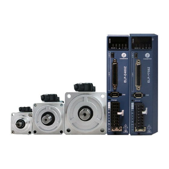
- Page 1 User manual of ELP AC Servo User Manual Of ELP AC Servo Ver1.35 www.leadshine.com...
- Page 2 Safety Items ELP Series servo drive, should be mounted in cover type control box during operating. The mounting of drive, wiring and motor should be under the regulations of EN 61800-5-1.
- Page 3 We mustn’t connect capacitors ,inductors or filters between servo motor and servo driver . The wire and temperature-resistant object must not be close to radiator of servo driver and motor. The freewheel diode which connect in parallel to output signal DC relay mustn’t connect reversely. www.leadshine.com...
- Page 4 The reason of fault must be figured out after alarm occurs, reset alarm signal before restart. Keep away from machine, because of restart suddenly if the driver is powered on again after momentary interruption(the design of the machine should be assured to avoid danger when restart occurs) www.leadshine.com...
- Page 5 User manual of ELP AC Servo Table of Contents Introduction ............................2 ELP series function guidance ...................... 8 Chapter 1 Introduction ........................9 1.1 Product Introduction ......................9 1.2 Inspection of product ......................9 Chapter 2 Product Specification ....................... 10 2.1 Driver Technical Specification ....................
- Page 6 9.4.1 Configuration software operation ................140 9.4.2 IO digital signal Trigger ..................142 9.4.3 RS485 Communication control mode ..............144 9.4.4 Fixed trigger method ....................147 9.4.5 Immediately trigger method ................... 148 9.5 Operation case ........................149 9.5.1 IO trigger case ......................149 www.leadshine.com...
- Page 7 10.2 Electronic Gear Ratio ...................... 158 Appendix ............................159 A、Modbus Communication ....................159 A.1 Wiring........................159 A.2 Parameters and interface for communication ............159 A.3 Modbus Protocol ...................... 160 A.4 RS485 common problems and solutions ..............163 Contact us ............................165 www.leadshine.com...
- Page 8 User manual of ELP AC Servo ELP series function guidance Function Details Section index Position control parameter specification, Position control 8.1 Position control guidance Velocity control parameter specification, Velocity control 6.2 Velocity control guidance Torque control parameter specification, Torque control 6.3 Torque control...
- Page 9 S/N:38AA1158200001MS10 www.leadshine.com Website b. Servo motor type The ELP series AC servo driver can be matched with a variety of domestic and foreign servo motor. 3. Accessory list 1. User manual 2. Power connector 3. Control signal terminal CN1 (44 pin)
- Page 10 Chapter 2 Product Specification Notice Warning Servo driver must be matched with relevant servo motor, this manual describes Leadshine ELP series servo motor. Contact tech@leadshine.com if you need more technical service . 2.1 Driver Technical Specification Table 2.1 Driver Specification A...
- Page 11 2.2 Accessory selection 1. Motor cable: CABLE-RZ3M0-S (V3.0) 2. Encoder cable: CABLE-7BM3M0-Z (V3.0) 3. Brake cable (if necessary): CABLE-SC3M0-S (V3.0) 4. Software configuration cable: CABLE-USB1M5 5. Control signal terminal CN1 (44 pin) 6. Control signal shell CN1 www.leadshine.com...
- Page 12 Protection IP20(no protection) IP54 or IP65 level Contact tech@leadshine.com if you need more technical service . 3.2 Servo Driver Installation Notice Must install in control cabinet with sufficient safeguarding grade. Must install with specified direction and intervals, and ensure good cooling condition.
- Page 13 Motor shaft does not bear the axial load, radial load, otherwise you may damage the motor. Use a flexible with high stiffness designed exclusively for servo application in order to make a radial thrust caused by micro misalignment smaller than the permissible value. Install must be steady, prevent drop from vibrating. www.leadshine.com...
- Page 14 Ground the earth terminal of the motor and driver without fail. The wiring should be connected after servo driver and servo motor installed correctly Contact tech@leadshine.com if you need more technical service . 4.1 Wiring 4.1.1 Wire Gauge (1)Power supply terminal TB ●...
- Page 15 User manual of ELP AC Servo The recommended regenerative resistance specifications for the ELP series are as follows: Table 4.2 Regenerative resistance specification sheet Built-in resister power (W) Driver Built-in resister value (Ω) ELP-*0400Z ELP-*0750Z ELP-*1000Z ELP-*1500Z ELP-*2000Z Method for determining regenerative resistance specification ...
- Page 16 Use twisted wire with 4.7K A-CLR shield for encoder signal S-RDY output BRK-OFF COM_SO COM_SO ALM+ ALM- BRKOFF+ BRKOFF- Figure 4-1 Positional Control Mode Wiring Note: For driver more than 1.5kw, 3 phase is better than single phase, connect L1,L2,L3 www.leadshine.com...
- Page 17 BRK-OFF AI3+ +10V-~-10V,use twisted wire with shield for torque AI3- COM_SO analog signal input ALM+ ALM- BRKOFF+ BRKOFF- Figure 4-2 Torque/Velocity Control Mode Wiring Note: For driver more than 1.5kw, 3 phase is better than single phase, connect L1,L2,L3 www.leadshine.com...
- Page 18 OC output terminal of motor encoder A phase output OC output terminal of motor encoder B phase output OC output terminal of motor encoder Z phase output OC output GND terminal of motor encoder input PUL+ Pulse input, www.leadshine.com...
- Page 19 Table 4.5 Encoder Input Port-CN2 Terminal Signal Explain Port Signal VCC5V BAT+ BAT- 4.2.3 RS232/RS485 Communication Port Table 4.6 signal explanation of driver interconnection interface-CN4 CN5 Port Signal 1,9 RDO+(RS485) 2,10 RDO-(RS485) 3,11 4,12 TXD(RS232) 5,13 RXD(RS232) 6,14 VCC5V(RS232) 7,15 GND(RS232) 8,16 www.leadshine.com...
- Page 20 When using external resistors, the values of resistance and power are selected as follows: Notes Driver Resistor(Ω) Power(W) ≥ 40 ELP-400 Port Signal Detail 3 phase motor power input Frame ground ① Connect the driver to the ground end (PE) of the motor and connect it to the Notes earth www.leadshine.com...
- Page 21 Range Unit Default 0~00FFFFFFh — Pr4.04* Data Type 16bit Access R/W Address 0409H Repower Name Input selection SI6 Mode Range Unit Default 0~00FFFFFFh — Pr4.05* Data Type 16bit Access R/W Address 040BH Repower Name Input selection SI7 Pr4.06* Mode www.leadshine.com...
- Page 22 Don’t setup to a value other than that specified in the table . Don’t assign specific function to 2 or more signals. Duplicated assignment will cause Err21.0 I/F input multiple assignment error 1or Err21.1 I/F input multiple assignment error 2 www.leadshine.com...
- Page 23 (3) If the load is inductive loads relays, etc., there must be anti-parallel freewheeling diode across the load. If the freewheeling diode is connected reversely, the servo drive is damaged. (4) 32、33、34、35、31 Pin:Single-ended output; 18、19 Pin ,20、21 Pin:Differencial output. www.leadshine.com...
- Page 24 Signal name Symbol Setup value Invalid Alarm output Servo-Ready output S-RDY Eternal brake release signal BRK-OFF Positioning complete output At-speed output AT-SPPED Zero-speed detection output Velocity coincidence output V-COIN Positional command ON/OFF output P-CMD Speed command ON/OFF output V-CMD www.leadshine.com...
- Page 25 VCC = 5V, R = 82 ~ 120Ω. (4) The user provide external power supply for single-ended drive. However, if current polarity connect reversely, servo driver is damaged. (5) The form of pulse input is the following form 3.7 below, while the arrows indicates the count. www.leadshine.com...
- Page 26 Range Unit — Default Data Type 16bit Access Address 000DH Repower Set command pulse input rotate direction, command pulse input type Name Command Pulse Input Mode Mode Pr0.07 Setup Range Unit — Default Data Type 16bit Access Address 000FH www.leadshine.com...
- Page 27 Max. Input Frequency Pulse Long distance interface 500kpps series Open-collector output 200kpps interface 4.3.4 Analog Value Input Interface Driver side Vin+ +/-10Vdc Vin- Figure 4-7 Analog AI1 Input Interface Driver side Vin+ +/-10Vdc Vin- Figure 4-8 Analog AI3 Input Interface www.leadshine.com...
- Page 28 User manual of ELP AC Servo 4.3.5 Servo Motor Encoder Input Interface Driver side Figure 4-9 Servo Motor optical-electrical Encoder Input Interface www.leadshine.com...
- Page 29 16bit 001BH position deviation — O — — 16bit 001DH excess setup — Absolute encoder setup 16bit 001FH External regenerative — 16bit 0021H discharge resistor setup External regenerative — 16bit 0023H discharge power value — 16bit 0033H Auxiliary function www.leadshine.com...
- Page 30 — O — — 16bit 0125H hysteresis — O — — 16bit Gain switching time 0127H Positional command O — — 16bit 0147H filter setup Encoder feedback pulse — 16bit 0149H digital filter setup — Special register 16bit 014BH www.leadshine.com...
- Page 31 — 0213H selection 1st damping 16bit — O — — 021DH frequency 2nd damping — O — — 16bit 0221H frequency Positional command O — — 16bit 022DH smooth filter Positional command O — — 16bit 022FH FIR filter www.leadshine.com...
- Page 32 Torque command input — — — 16bit 0329H reversal — — — Speed limit value 1 16bit 032BH — 2nd torque limit 16bit 032DH Maximum speed of — 16bit 0331H motor rotation Synchronous parameter — 16bit 0339H setting of gantry www.leadshine.com...
- Page 33 — — 16bit At-speed 1000 0449H Mechanical brake — 16bit 044BH action at stalling setup Mechanical brake — 16bit 044DH action at running setup Brake action at — 16bit 044FH running setup — E-stop function active 16bit 0457H www.leadshine.com...
- Page 34 RS485 baud rate setup 16bit 053DH RS485 slave axis — 16bit 053FH address Command pulse input — O — — 16bit 0541H maximum setup — Front panel lock setup 16bit 0547H Password for opening — 16bit 0549H group 7 parameter www.leadshine.com...
- Page 35 — O — — 16bit 062BH running cycling times of trial — O — — 16bit 062DH running Acceleration of trial — O — — 16bit 0633H running Absolute multi-turn 16bit 067FH position upper bound www.leadshine.com...
- Page 36 (1)The "O" in the repower bar indicates that the new value valid after repower, and the "-" indicates that the new value valid immediately; (2)The "O" in the mode bar indicates this parameter related to this mode, “—”indicates this parameter dose not related to this mode; (3)32bit data,high data before, low data after. www.leadshine.com...
- Page 37 User manual of ELP AC Servo 5.2 Parameter Function Here is the explanation of parameters ,you can check them or modify the value using software Protuner or the front panel of driver. Contact tech@leadshine.com if you need more technical service . 【 】 5.2.1...
- Page 38 When the inertia ratio of Pr0.04 is larger than the actual value, the setup unit of the velocity loop gain becomes larger, and when the inertia ratio of Pr0.04 is smaller than the actual value, the setup unit of the velocity loop gain becomes smaller.. www.leadshine.com...
- Page 39 Set the command pulse that causes single turn of the motor shaft. 1) If Pr008 ≠ 0 , the actual turns = pulse number / Pr008 2) If Pr008 = 0 , Pr0.09 1 numerator of electronic gear and Pr0.10 Denominator of electronic Gear become valid. www.leadshine.com...
- Page 40 Data Type 16bit Access Address 0017H Repower Set the numerator of division/multiplication operation made according to the command pulse input Name reversal of pulse output logic Mode Range Unit — Default Pr0.12* Data Type 16bit Access Address 0019H Repower www.leadshine.com...
- Page 41 The encoder is used as an absolute encoder, and the position retentive at power failure is supported.. It is mainly applicable to the scenario where the load travel range is not limited and the number of motor single-direction revolution is less than 0~(Pr6.63+1) 5: Clean multi-turn alarm, and open multi-turn absolute function. www.leadshine.com...
- Page 42 Repower Value Auxiliary function 0x1111 Reset current alarm 0x1122 Reset history alarm 0x2211 Save parameter 0x2222 Reset to factory setting except motor parameters 0x2233 Reset to factory setting 0X4001 JOG_P(50ms time period) 0X4002 JOG_N(50ms time period) 0x6666 Soft reset www.leadshine.com...
- Page 43 0.The integration will be maintained by setting to”9999”.The integration effect will be lost by setting to”10000”. Name Mode 1st Filter of Velocity Detection Range Unit Default 0~31 — Pr1.03 Data Type 16bit Access Address 0107H Repower www.leadshine.com...
- Page 44 2nd gain of velocity loop Mode Range Unit Default 0~32767 0.1Hz Pr1.06 Data Type 16bit Access Address 010DH Repower Name 2nd Time Constant of Velocity Mode Loop Integration Range Unit Default 0~10000 0.1ms 10000 Pr1.07 Data Type 16bit Access Address 010FH Repower www.leadshine.com...
- Page 45 Data Type 16bit Access Address 0119H Repower Multiply the torque control command calculated according to the velocity control command by the ratio of this parameter and add the result to the torque command resulting from the velocity control process. www.leadshine.com...
- Page 46 1st gain. Return to the 1st gain when the positional command was kept at 0 during the delay time and the absolute value of actual speed was kept below (level - hysteresis) (r/min) previously with the 2nd gain. www.leadshine.com...
- Page 47 Example: 1 st (pr1.00) <-> 2nd (Pr1.05) Name Mode positional command filter setup Range Unit Default 0~200 0.05us Pr1.35* Data Type 16bit Access Address 0147H Repower www.leadshine.com...
- Page 48 3rd notch filter will be time updated all the time based on adaptive performance. Not use Non-professional forbidded to use Name Mode 1st notch frequency Range Unit Default 50~2000 2000 Pr2.01 Data Type 16bit Access Address 0203H Repower www.leadshine.com...
- Page 49 — Pr2.06 Data Type 16bit Access Address 020DH Repower Set the depth of notch at the center frequency of the 2nd notch filter. Notice: Higher the setup, shallower the notch depth and smaller the phase delay you can obtain. www.leadshine.com...
- Page 50 2nd damping frequency Mode Range Unit Default 10~2000 0.1HZ Pr2.16* Data Type 16bit Access Address 0221H Repower 0: close Setup damping frequency, to suppress vibration at the load edge Name positional command Mode smoothing filter Pr2.22 Range Unit Default 0~32767 0.1ms www.leadshine.com...
- Page 51 When a square wave command for the target speed Vc is applied , set up the Vc arrival time as shown in the figure below. 【 】 5.2.4 Class 3 Velocity/ Torque Control Name Speed setup, Internal /External Mode switching Range Unit Default — Pr3.00 Data Type 16bit Access Address 0301H Repower www.leadshine.com...
- Page 52 Select the Positive /Negative direction specifying method Setup Select speed Speed command Position command value command sign (1st direction direction to 8th speed) (VC-SIGN) No effect Positive direction No effect Negative direction Sign has no effect Positive direction Sign has no effect Negative direction www.leadshine.com...
- Page 53 Caution: When you compose the servo drive system with this driver set to velocity control mode and external positioning unit, the motor might perform an abnormal action if the polarity of the speed command signal from the unit and the polarity of this parameter setup does not match. www.leadshine.com...
- Page 54 Default -10000~10000 r/min Pr3.10 Data Type 16bit Access Address 0315H Repower Name Mode 8th speed of speed setup Range Unit Default -10000~10000 r/min Pr3.11 Data Type 16bit Access Address 0317H Repower Set up internal command speeds, 1st to 8th www.leadshine.com...
- Page 55 Access Address 031DH Repower Set S-curve time for acceleration/deceleration process when the speed command is applied. According to Pr3.12 Acceleration time setup and Pr3.13 Deceleration time setup, set up sigmoid time with time width centering the inflection point of www.leadshine.com...
- Page 56 Analog input 3 Analog input 1 for Speed limit Parameter value (P3.22) Parameter value (P3.21) Analog input 3 Speed limit 0 Name Torque command direction Mode selection Range Unit Default — Pr3.18 Data Type 16bit Access Address 0325H Repower www.leadshine.com...
- Page 57 Speed limit value 1 Mode Range Unit Default 0~10000 r/min Pr3.21 Data Type 16bit Access Address 032BH Repower Set up the speed limit used for torque control. During the torque controlling, the speed set by the speed limit cannot be exceeded. www.leadshine.com...
- Page 58 0405H Repower Name Input selection SI4 Mode Range Unit Default 0~00FFFFFFh — Pr4.03* Data Type 16bit Access R/W Address 0207H Repower Name Input selection SI5 Mode Range Unit Default Pr4.04* 0~00FFFFFFh — Data Type 16bit Access R/W Address 0409H www.leadshine.com...
- Page 59 Selection 1 input of internal command INTSPD1 speed Selection 2 input of internal command INTSPD2 speed Selection 3 input of internal command INTSPD3 speed Speed zero clamp input ZEROSPD Speed command sign input VC-SIGN Torque command sign input TC-SIGN Forced alarm input E-STOP www.leadshine.com...
- Page 60 Output selection SO3 Mode Range Unit Default 0~00FFFFFFh — Pr4.12* Data Type 16bit Access Address 0419H Repower Name Mode Output selection SO4 Range Unit Default 0~00FFFFFFh — Pr4.13* Data Type 16bit Access Address 041BH Repower Name Output selection SO5 Mode Pr4.14* www.leadshine.com...
- Page 61 Analog input 1 (AI1) filter Mode Range Unit Default 0~6400 0.01ms Pr4.23 Data Type 16bit Access Address 042FH Repower Set up the time constant of 1st delay filter that determines the lag time behind the voltage applied to the analog input 1. www.leadshine.com...
- Page 62 Encoder unit Default 0~10000 Pr4.31 Data Type 16bit Access Address 043FH Repower Set up the timing of positional deviation at which the positioning complete signal (INP1) is output. Name Positioning complete output Mode setup Pr4.32 Range Unit Default command unit www.leadshine.com...
- Page 63 Pr4.34 The setup of pr4.34 is valid for both positive and negative direction regardless of the motor rotating direction. There is hysteresis of 10[r/min] www.leadshine.com...
- Page 64 Set the detection timing of the speed arrival output (AT-SPEED). When the motor speed exceeds this setup value, the speed arrive output (AT-SPEED) is output. Detection is associated with 10r/min hysteresis . Name Mechanical brake action at Mode Pr4.37 stalling setup www.leadshine.com...
- Page 65 Pr4.39 setup speed Name Brake release speed setup Mode Range Unit Default 30~3000 Pr4.39 Data Type 16bit Access Address 044FH Repower When servo off, rotate speed less than this setup vale, and mechanical brake start delay time arrive, motor lost power. www.leadshine.com...
- Page 66 0: positive and negative limit effective, no alarm output; positive and negative limit effective invalid; positive and negative limit effective, alarm output; Name Mode Sequence at servo-off Range Unit Default — Pr5.06 Data Type 16bit Access Address 050DH Repower www.leadshine.com...
- Page 67 1:Dynamic braking is valid in normal condition, invalid in abnormal condition. (used to prevent abnormal conditions, high speed and large inertia to burn up the dynamic braking) 2:Dynamic braking is invalid in both normal and abnormal conditions. Name Torque setup for emergency stop Mode Pr5.11* www.leadshine.com...
- Page 68 16bit Access Address 0523H Repower Set up the clearing conditions of the counter clear input signal Setup value Clear condition 0/2/4 invalid Always clear Only clear one time Name Position setup unit select Mode Pr5.20 Range Unit Default — www.leadshine.com...
- Page 69 16bit Access Address 0531H Repower Default setting is 0,if the torque feedback is greater than 95% of the rated torque, output TCL signal. If the torque feedback is greater than the user setting value, output TCL signal. www.leadshine.com...
- Page 70 Access Address Repower Value Data bit Parity-check Stop bit Even Parity Odd Parity Even Parity Odd Parity None None Name Baud rate setup of RS485 Mode communication Range Unit Default — Pr5.30* 16bit 053DH Data Type Access Address Repower www.leadshine.com...
- Page 71 No limit on the front panel operation Lock the operation on the front panel Name Mode setting parameters open Range Unit Default 0、102 — Pr5.36 Data Type 16bit Access Address 0549H Repower 7th setting parameters open. Setup value content Open 7 setting parameters modification authority. www.leadshine.com...
- Page 72 3rd gain= 1st gain * PR6.06/100. Name Torque command additional Mode value Range Unit Default -100~100 Pr6.07 Data Type 16bit Access Address 060FH Repower Name Positive torque compensation Mode value Pr6.08 Range Unit Default -100~100 Data Type 16bit Access Address 0611H www.leadshine.com...
- Page 73 The distance of running each time in JOG run(position control) Name Trial run waiting time Mode Range Unit Default 0~30000 Pr6.21 Data Type 16bit Access Address 062BH Repower The waiting time after running each time in JOG run(position control) www.leadshine.com...
- Page 74 PrB.00 Data Type 16bit Access Address 0B00H Display Software version 1(DSP) Name Software version 2(CPLD) Mode Range Unit Default PrB.01 Data Type 16bit Access Address 0B01H Display Software version 2(CPLD) Name Mode Software version 3(other) PrB.02 Range Unit Default www.leadshine.com...
- Page 75 Data Type 16bit Access Address 0B08H Actual current feedback Name Speed(After filtering) Mode Range Unit Default PrB.09 Data Type 16bit Access Address 0B09H Speed(After filtering) Name DC bus voltage Mode Range Unit Default PrB.10 Data Type 16bit Access Address 0B0AH www.leadshine.com...
- Page 76 Access Address 0B0FH Over-load ratio(%) Name Regeneration load ratio Mode Range Unit Default PrB.16 Data Type 16bit Access Address 0B10H Regeneration load ratio(%) Name Digital input signal status Mode Range Unit Default PrB.17 Data Type 16bit Access Address 0B11H www.leadshine.com...
- Page 77 8388608 pulse/r, then the driver motor position feedback pulse number is 10000P Name Command pulse sum(Command Mode unit) PrB.21 Range Unit Default Data Type 32bit Access Address 0B16H~0B17H Command pulse sum(Command unit) Name Positional deviation(Command Mode unit) PrB.22 Range Unit Default Data Type 32bit Access Address 0B18H~0B19H www.leadshine.com...
- Page 78 Default PrB.25 Data Type 32bit Access Address 0B1EH~0B1FH Positional deviation(encoder unit) Name Position feedback in rotation Mode mode(encoder unit) PrB.26 Range Unit Default Data Type 32bit Access Address 0B29H~0B21FH Position feedback in rotation mode(encoder unit),refer to PrB.23 for details. www.leadshine.com...
- Page 79 I/F input interface allocation error ● ● I/F input interface function set error ● ● I/F output interface function set error CRC verification error when EEPROM parameter saved ● ● ● Positive/negative over-range input valid ● ● Compulsory alarm input valid www.leadshine.com...
- Page 80 Display: 0A5” code Content: DC bus circuit error Cause Confirmation Solution Main voltage L1,L2,L3 Check L1,L2,L3 terminal Make sure voltage of L1,L2,L3 terminal terminal under-voltage voltage in proper range Driver inner fault replace the driver with a new one www.leadshine.com...
- Page 81 Adjust parameter to proper range parameter Check control command whether abnormal setting of control Adjust control command: open command changes too violently or command filter function Error “Er Main Extra Display: 0E1” code Content: IPM over-current Cause Confirmation Solution www.leadshine.com...
- Page 82 Check the load if it is inertia ,increase external regenerative resistor, regenerative resistor . too large or not. improve the capacity of the driver and motor Resistance discharge Increase external regenerative resistor, replace circuit damage the driver with a new one www.leadshine.com...
- Page 83 /Clear drive alarm Clear alarm after changing battery Error “Er Main Extra Display: 170” code Content: encoder data error Cause Confirmation Solution Communication data Check encoder power voltage if it is Ensure power voltage of encoder www.leadshine.com...
- Page 84 Main Extra Display: 190” Error code Content: motor vibration Cause Confirmation Solution Current vibration Current vibration Cut down the value of Pr003. Pr004 Current loop is too strong Current loop is too strong Error “Er Main Extra Display: 1A0” www.leadshine.com...
- Page 85 Check the value of PA_400, Assure parameter PA_400, PA_401, The input signal aren’t PA_401,PA_402,PA_403,PA_404 PA_402,PA_403,PA_404 set assigned with any functions. if it is proper or not correctly Error “Er Main Extra Display: 211” www.leadshine.com...
- Page 86 Try to adjust analog input within limited Analog input out of range range Display: “ Main Extra 570” Error code Content: forced alarm input valid Cause Confirmation Solution Forced-alarm input signal Check forced-alarm input signal Assure input signal wiring correctly has been conducted www.leadshine.com...
- Page 87 2、 Set IO input function as Alarm clear input “ (A-CLR)”, refer to switch input interface connection to clear the alarm For alarm can not be cleared: 1、 Restart the power-supply to clear the alarm. www.leadshine.com...
- Page 88 Press this key to increase the set value of current flash bit ▼ Down key Press this key to decrease the set value of current flash bit ◄ Left key Press this key to shift to the next digit on the left www.leadshine.com...
- Page 89 (x, y is numerical value) Low-bit “L xxxx” Positional command d00uE d00uE pulse High-bit ”H xxxx” deviation “r xxxx” d01SP Motor speed d01SP r/min Positional command “r xxxx” d02cS d02CS r/min speed Velocity control “r xxxx” d03cu d03Cu r/min command www.leadshine.com...
- Page 90 Software version “P xxx” “n xxx” d29AS Driver serial number d29AS Low-bit “L xxxx” d30sE d30NS Motor serial number High -bit”H xxxx” Low-bit “L xxxx” Accumulated operation d31 tE d31tE High -bit”H xxxx” time “r xxx” d32Au d32Au Automatic motor www.leadshine.com...
- Page 91 The fourth and fifth decimal places on the right indicate negative Numbers, otherwise positive Numbers Users can choose to set the initial display state of power supply to any of the below: Name LED initial status Mode Range Unit Default 0~35 — Pr5.28* Data Type 16bit Access Address 0539H Repower www.leadshine.com...
-
Page 92: Table Of Contents
2.press ▲ once to display “InI---”, indicated AFInI AFInI of parameter initialization; after finishing it, display“FinSh”。 Release of 1. press SET to enter operation, display “unL -”。 AFunL AFunL front panel 2. press ▲button one time , display lock www.leadshine.com... - Page 93 4. “Error” means that writing is unsuccessful, while “Finish” show that the writing is successful; Follow steps 3 and 4 to repeat the operation; the drive may be damaged if repeat of several times still fails. The driver need to www.leadshine.com...
- Page 94 Note: there are two kinds of trial run : trial run without load and trial run with load . The user need to test the driver without load for safety first. Contact tech@leadshine.com if you need more technical service . 7.3.1 Inspection Before trial Run Table7.6 inspection Item Before Run...
- Page 95 ,refer to chapter 7.1.2 timing chart on power-up. You can follow the diagram about the wiring below : About the wire of brake ,there should be an 24VDC for brake, the brake will be loosed with the 24VDC www.leadshine.com...
- Page 96 (hold "sub-menu, find the cause why motor doesn’t rotate, fix the rotate, switch to data monitoring mode d17 Ch trouble and try again; 8. Press SET will exit JOG control in JOG run mode. www.leadshine.com...
- Page 97 Chapter 8 Application Case Operation Mode Selection ELP series AC servo drives support the position, speed, torque three basic modes of operation, and can switch freely between the three basic modes of operation by switch or modify parameters. Table 8.1 Parameter setup of Operation Mode Selection...
- Page 98 The motor stops by stopping the command (pulse) or not If the motor does not run correctly, refer to the Factor of No-Motor running in data monitor mode ("d17Ch " ). The driver is widely used for precise positioning in position control mode. www.leadshine.com...
- Page 99 Use twisted wire with 4.7K A-CLR shield for encoder signal S-RDY output BRK-OFF COM_SO COM_SO ALM+ ALM- BRKOFF+ BRKOFF- Figure 8-2 Position Mode Typical Wiring Diagram Note: For driver is more than 1.5kw, 3 phase is better than single phase, connect L1,L2,L3 www.leadshine.com...
-
Page 100: Setup
Pulse Pulse + sign sign Command pulse input signal allow largest frequency and smallest time width Permissible Smallest Time Width PULS/SIGN Signal Input I/F Max. Input Frequency Pulse Long distance interface 500kpps series Open-collector output 200kpps interface www.leadshine.com... - Page 101 2)The pulse number of encoder after frequency division and frequency doubling is Y 3)The number of pulses per revolution of the motor encoder is Z 4)Number of turns of motor is W 2. Calculations: 1)Y=X* Pr0.09 / Pr0.10 2)17Bit encoder: Z=2^17 = 131072 23Bit encoder: Z=2^23 = 8388608 www.leadshine.com...
-
Page 102: Positional Command Deviation
8.1.4 Motor encoder pulse output The information on the amount of movement can be sent to the host controller in the form of A and B phase pulses from the servo driver. www.leadshine.com... - Page 103 16bit Access Address 043FH Repower Set up the timing of positional deviation at which the positioning complete signal (INP1) is output. Name Mode Positioning complete output setup Pr4.32 Range Unit command Default unit Data Type 16bit Access Address 0441H www.leadshine.com...
-
Page 104: 8.2 Velocity Control
Setup value Unit Pr0.01 Control mode setup Acceleration time setup millisecond Pr3.12 User-specified Deceleration time setup millisecond Pr3.13 User-specified Sigmoid acceleration/deceleration time millisecond Pr3.14 User-specified setup Pr3.15 Zero speed clamping function select Velocity setup internal and external Pr3.00 User-specified switching www.leadshine.com... - Page 105 ("d17Ch " ). The driver is widely used for accuracy speed control in velocity control mode. You can control the speed according to the analog speed command from the host controller or the speed command set in servo driver. www.leadshine.com...
- Page 106 +10V-~-10V,use twisted wire with shield for torque AI3- COM_SO analog signal input ALM+ ALM- BRKOFF+ BRKOFF- Figure 8-3 Velocity Mode Typical Wiring Diagram Note: For driver is more than 1.5kw, 3 phase is better than single phase, connect L1,L2,L3 www.leadshine.com...
- Page 107 3rd speed Analog speed command The same as [Pr3.00=1] 1st to 4th speed 5th speed 6th speed 7th speed 8th speed Name Mode Speed command rotational direction selection Range Unit Default — Pr3.01 Data Type 16bit Access Address 0303H Repower www.leadshine.com...
- Page 108 [+ direction] [- voltage] [-direction] reversal [+ voltage] [- direction] [- voltage] [+direction] Caution: When you compose the servo drive system with this driver set to velocity control mode and external positioning unit, the motor might perform an abnormal www.leadshine.com...
- Page 109 3rd speed Analog speed command The same as [Pr3.00=1] 1st to 4th speed 5th speed 6th speed 7th speed 8th speed Name Speed command rotational Mode direction selection Range Unit Default — Pr3.01 Data Type 16bit Access Address 0303H Repower www.leadshine.com...
- Page 110 [+ direction] [- voltage] [-direction] reversal [+ voltage] [- direction] [- voltage] [+direction] Caution: When you compose the servo drive system with this driver set to velocity control mode and external positioning unit, the motor might perform an abnormal www.leadshine.com...
- Page 111 Name 7th speed of speed setup Mode Range Unit Default -10000~10000 r/min Pr3.10 Data Type 16bit Access Address 0315H Repower Name 8th speed of speed setup Mode Range Unit Default Pr3.11 -10000~10000 r/min Data Type 16bit Access Address 0317H www.leadshine.com...
- Page 112 Acceleration time (ms)=Vc/1000 *Pr3.12 *1ms Deceleration time (ms)=Vc/1000 *Pr3.13 *1ms Name Mode Sigmoid acceleration /deceleration time setup Range Unit Default 0~1000 Pr3.14 Data Type 16bit Access Address 031DH Repower www.leadshine.com...
- Page 113 This function can be configured by IO output function parameters, as described in IO Pr4.10 parameters. When the speed difference meets the setting conditions, the corresponding output IO port set can output ON. Among them, the in place signal of PV mode is synchronized with the v-coin signal www.leadshine.com...
- Page 114 3. If Pr3.15=2 , the function of zero clamp belongs to the value of Pr3.16. If the actual velocity is less than the value of Pr3.16, the motor will stop rotating in servo-on condition. Name Speed zero-clamp level Mode Range Unit Default Pr3.16 10~2000 r/min Data Type 16bit Access Address 0321H www.leadshine.com...
- Page 115 8. When you want to change the torque magnitude, direction and velocity limit value against the command voltage, set up the following parameters : Pr3.19. Pr3.20. Pr3.21 If the motor does not run correctly, refer to the Factor of No-Motor running in data monitor mode ("d17Ch " ). www.leadshine.com...
- Page 116 +10V-~-10V,use twisted wire with shield for torque AI3- COM_SO analog signal input ALM+ ALM- BRKOFF+ BRKOFF- Figure 8-4 Torque Mode Typical External Wiring Diagram Note: For driver is more than 1.5kw, 3 phase is better than single phase, connect L1,L2,L3 www.leadshine.com...
-
Page 117: Torque Command
Torque command input[+] positive direction, [-] negative direction Specify the direction with torque command sign(TC-SIGN). OFF: positive direction ON: negative direction Name Torque command input gain Mode Range Unit Default 10~100 0.1V/100% Pr3.19 Data Type 16bit Access Address 0327H Repower www.leadshine.com... - Page 118 Direction of motor output torque value Non-reversal [+ voltage] [+ direction] [- voltage] [-direction] reversal [+ voltage] [- direction] [- voltage] [+direction] Name Speed limit value 1 Mode Range Unit Default 0~10000 r/min Pr3.21 Data Type 16bit Access Address 032BH Repower www.leadshine.com...
-
Page 119: Inertia Ratio
The depth of the trap is: when the set value is 0, the input of the center frequency is completely disconnected; When the set value is 100, it represents the ratio of input and output that are completely passed www.leadshine.com... - Page 120 — Pr2.03 Data Type 16bit Access Address 0207H Repower Set the depth of notch at the center frequency of the 1st notch filter. Notice: Higher the setup, shallower the notch depth and smaller the phase delay you can obtain. www.leadshine.com...
- Page 121 9.51 1.00 3.36 11.31 1.19 4.00 13.45 1.41 4.76 16.00 8.6 Third gain switching In addition to the conventional switch between the first and second gain, add the third gain switch function to shorten the positioning and setting time. www.leadshine.com...
- Page 122 3rd gain: Position loop gain=Pr1.00 Pr6.06/100 Velocity loop gain=Pr1.01 Pr6.06/100 8.7 Friction torque compensation Name Torque command additional Mode value Range Unit Default -100~100 Pr6.07 Data Type 16bit Access Address 060FH Repower Name Positive torque compensation Mode Pr6.08 value www.leadshine.com...
- Page 123 Set Pr.0.16 and Pr.0.17 to confirm the threshold value of the discharge loop to give alarm for over current. 8.9 Security Features 8.9.1 Speed limit Name Motor rotate maximum speed Mode limit Pr3.24* Range Unit Default 0~10000 r/min 3000 Data Type 16bit Access Address 0331H www.leadshine.com...
- Page 124 It is unnecessary to return to zero in the future (except for the absolute encoder alarm and other situations). It is recommended that the motor is stationary when reading the position to prevent dynamic data jump. 8.10.1 Parameters setting Name Absolute Encoder Setup Mode Pr0.15 www.leadshine.com...
- Page 125 Set to 9 after homing process finished and servo disabled., ,valid after repower. 8.10.2 Read absolute position 1、Steps: Install battery Pr0.15=1 Home process Finishing Homing process, set Pr0.15=9 Read absolute position *Note:The newly installed encoder is not initialized and will alarm www.leadshine.com...
- Page 126 (3)When the battery voltage is lower than 2.5v, or the battery has a power failure, the absolute encoder alarm will be generated. Even if the battery is replaced, the alarm cannot be eliminated. At this time, the return to the home point and multi-turn zero clearing operation should be performed 4、Alarm processing flow chart www.leadshine.com...
- Page 127 Pr4.34 The setup of pr4.34 is valid for both positive and negative direction regardless of the motor rotating direction. There is hysteresis of 10[r/min] www.leadshine.com...
- Page 128 Position setup unit select Mode Range Unit Default — Pr5.20 Data Type 16bit Access Address 0529H Repower Specify the unit to determine the range of positioning complete and excessive positional deviation Setup value unit Encoder unit Command unit 10000pulse/rotation www.leadshine.com...
- Page 129 1、Limit signal homing, home signal homing, and manual homing all selectable, 2、Homing direction settable 3、Home deviation position settable. Can be positioned to the specified location after homing. 4、Homing acceleration and deceleration settable Remark:Cannot input external pulse during homing! Trigger positive/negative point move by I/O, for debugging www.leadshine.com...
- Page 130 9.1.2 Installation wiring 485 communication terminal connection diagram: Port Signal RDO+ 1,9 RDO- 2,10 3,11 4,12 5,13 VCC5V 6,14 7,15 8,16 IO terminal wiring and parameter configuration:Newly added IO of PR on the base of standard IO Relevant parameters: www.leadshine.com...
- Page 131 Torque switch TC-SEL Remark:CMD_OK means PR instruction is sent,maybe motor is not yet in place. MC_OK means PR instruction is sent and motor is in place. CTRG、HOME is edge trigging, but effective level need to last more than 1ms. www.leadshine.com...
- Page 132 =0:homing with limit switch detect =1:homing with homing switch detect =2:homing with single turn Z signal detect =3:homing with torque detect =8:set current position as homing point Bit8: =0:homing process without Z signal detect =1:homing process with Z signal detect www.leadshine.com...
- Page 133 0X602C Motor position H Pr8.45 0X602D Motor position L 9.2.2 9th parameters specification Parameters Name Definition address The motion mode of Path0 motion Bit0-3:TYPE: 0 No Action Pr9.00 0X6200 Path0 Mode 1 position mode 2 velocity mode 3 homing www.leadshine.com...
- Page 134 Bit0:=0, CTRG rising edge trigger =1, double edge trigger, Pr8.00 0X6000 Pr control setting Bit1:Software limit effectively,0 invalid / 1 valid Bit2:Homing after power on ,0 invalid / 1 valid Bit3: Absolute encoder function, 0 invalid / 1 valid www.leadshine.com...
- Page 135 Homing high speed Pr8.16 0X6010 Homing low speed Pr8.17 0X6011 Homing acceleration Pr8.18 0X6012 Homing deceleration Holding time of homing Pr8.19 0X6013 with torque detect Torque value of homing Pr8.20 0X6014 with torque detect Overpass distance setting Pr8.21 0X6015 while homing www.leadshine.com...
- Page 136 2 velocity mode 3 homing 4 stop Bit4: INS, 0 do not interrupt Pr9.00 0X6200 Path0 Mode 1 interrupt (All interrupt now) Bit5: OVLP, do not overlap overlap Bit6-7: absolute position relative to command 2 relative to motor Bit8-13: www.leadshine.com...
- Page 137 9.3.2.2 Multi path interrupt motion Interrupt function means a higher path's priority. Interrupt the current valid path, give up the current path and run the new path directly. Similar to the interrupt priority level of functions. Pr9.00 bit4 = 0, interrupt www.leadshine.com...
- Page 138 CTRG Path5 Path 9 ADD0~3 Continuous path finished CMD_OK 9.3.2.4 Continuous path motion with overlap After arriving at the first path position, start another path motion automatically without trigger signal. Pr9.00 bit5 = 1, continuous path motion with overlap www.leadshine.com...
- Page 139 Negative software limit L Pr8.22 0X6016 Position limit e-stop speed Pr8.23 0X6017 E-stop speed Pr3.12 0X0319 JOG Acceleration time Unit: ms/1000rpm Pr3.13 0X031B JOG Deceleration time Unit: ms/1000rpm Pr6.04 0X0609 JOG speed Unit: rpm Input terminal 1、 JOG Manual point move function www.leadshine.com...
- Page 140 3. Setting up the PR basic control parameters through upper computer's "Pr-Mode" interface. Include: trigger setting, software limit, JOG function, homing function, e-stop function and so on. 4. Setting up the PR positioning path parameters through upper computer's " Pr-MODE " interface, include: www.leadshine.com...
- Page 141 User Manual for ELP Servo www.leadshine.com...
- Page 142 Click the number marked red in the figure and click start to run according to the speed in the path parameter configuration diagram. Click the corresponding number and click to run at the configured speed. If not, check that the parameters are set correctly 9.4.2 IO digital signal Trigger Pr-Mode motion can be triggered by IO signal. www.leadshine.com...
- Page 143 The trigger mode of path motion is divided into edge trigger and IO combination trigger. Determined by control parameter Pr8.26; The edge trigger selects the motion path by the combination of paths, and then triggers the edge event of IO CTRG signal to start a motion. The IO combination trigger means that the www.leadshine.com...
- Page 144 Communications control includes two modes: Fixed trigger mode and immediately trigger mode. 9.4.3.1 Parameters setting Parameters Name Specification Control Mode Setup Set Pr0.01=6 for Pr-Mode Pr0.01 Set 83 for internal Servo-Enable SI1 Input selection Pr4.00 Set 03 for external Servo-Enable(Digital SI input for Servo-Enable ) www.leadshine.com...
- Page 145 485 communication address of Pr-Mode 485 address Parameter Name Specification 0x6000 Pr8.00 PR control setup 0x6002 Pr8.02 PR control register Pulse 0x6006 Pr8.06 Positive software limit H Pulse 0x6007 Pr8.07 Positive software limit L Pulse 0x6008 Pr8.08 Negative software limit H www.leadshine.com...
- Page 146 Pr9.24~Pr9.31 Path 3 parameters The same with Pr9.00~Pr9.07 0x6220~0x6227 Pr9.32~Pr9.39 Path 4 parameters The same with Pr9.00~Pr9.07 0x6228~0x622f Pr9.40~Pr9.47 Path 5 parameters The same with Pr9.00~Pr9.07 0x6230~0x6237 Pr9.48~Pr9.55 Path 6 parameters The same with Pr9.00~Pr9.07 0x6238~0x623f Pr9.56~Pr9.63 PR7 parameters www.leadshine.com...
- Page 147 Set path 0 parameters as the table showing , path 1~path15 parameters are the same as path 0 Parameters Name Definition address The motion mode of Path0 motion Bit0-3:TYPE: Pr9.00 0X6200 Path0 Mode 0 No Action 1 position mode www.leadshine.com...
- Page 148 Pr8.02, write in 0x10 can trigger path0 motion immediately. As below procedure: 1. Firstly, configure homing and path which need to run, set these parameters by communication or set these parameters and save with upper computer. (homing must be configured) 2. Enable drive. www.leadshine.com...
- Page 149 Pr4.00 Set 03 for external SERVO-ON Specific of the 9 input terminals' function distribution, SI input selection Pr4.00-Pr4.08 refer to functional allocation table. Specific of the 6 output terminals' function SO output selection Pr4.10-Pr4.15 distribution,refer to functional allocation table. www.leadshine.com...
- Page 150 Position symbol description area: Explains the meaning of the path position symbol. Notes: After the path parameter setting is completed, click the Download button of the toolbar to make the parameters valid. Click Save button to save the parameter to drive permanently. www.leadshine.com...
- Page 151 User Manual for ELP Servo 4、Debug homing process, path trigger motion, input and output, etc. Its debugging interface is shown as follow: Notes 1: Before using IO CTRG edge signal trigger path motion, select path number by IO combined signal, www.leadshine.com...
- Page 152 01 06 62 05 00 32 07 A6 DEC: 50ms/1000rpm 01 06 60 02 00 10 37 C6 Trigger Path0 motion 01 06 60 02 00 40 37 FA E-stop 01 06 20 09 00 00 52 08 Servo disable www.leadshine.com...
- Page 153 00 64 A6 22 High speed for homing 01 06 60 10 00 1E 16 07 Low speed for homing 01 06 60 02 00 20 37 D2 Trigger Homing process 01 06 60 02 00 40 37 FA E-stop www.leadshine.com...
- Page 154 P9.00 Mode XXXX 10-11 P9.01 High position XXXX 12-13 P9.02 Low position XXXX Speed 14-15 P9.03 XXXX Acceleration 16-17 XXXX P9.04 Deceleration 18-19 XXXX P9.05 Delay time 20-21 XXXX P9.06 Trigger control 22-23 P9.07 0x0010 Check code www.leadshine.com...
- Page 155 Motion Mode, relative position mode 00 01 86 A0 data written down to the second and third addresses of 6201 mapped to Pr9.01;6202 mapped to Pr9.02. Hexadecimal data of position=100000plus. All positions in PR mode are in units of 10000P/r, www.leadshine.com...
- Page 156 F6 12 the verification code, do not have to directly input, click the corresponding send area verification button automatically generated After the current position is set to zero manually, you can click absolute positioning again to send it manually, www.leadshine.com...
- Page 157 The final analysis is as follows: speed=1000r/min, acceleration and deceleration time is 100ms, velocitymode E-stop: 01 06 60 02 00 40 37 FA Servo enable: 01 06 20 09 00 01 93 C8 Servo disable: 01 06 20 09 00 00 52 08 www.leadshine.com...
- Page 158 ×mechanical reduction ratio. 【Note】If the electronic gear ratio of G is not 1, gear ratio division may have the remainder, then there will be position deviation existed, the maximum deviation is the minimum of rotation ( minimum resolution ). www.leadshine.com...
- Page 159 Pr5.29* Range Unit Default 0~255 — 16bit 053BH Data Type Access Address Repower Value Data bit Parity-check Stop bit Even Parity Odd Parity Even Parity Odd Parity None None Name Mode Baud rate setup of RS485 Pr5.30* communication www.leadshine.com...
- Page 160 A.3 Modbus Protocol The driver supports 16bit data read and write of Modbus-RTU protocol, and its function codes include 0x03,0x06 and 0x10. 0x03 read data function code, 0x06 write single data function code and 0x10 write multiple data function code. Notes:1word=2byte=16bit www.leadshine.com...
- Page 161 Check code Notes:The number of receive frame is the same as the send frame. The communication data is shown as below: [Send] 01 06 00 04 00 02 49 CA [Receive] 01 06 00 04 00 02 49 CA www.leadshine.com...
- Page 162 When there is a mistake in the format of the send frame data, the slave feeds back the wrong reply frame data to the master station. The format is as follows: Error response frame data(Slave-->Master) Slave ID 0~31 Function code (0x03/0x06/0x10)+0x80 Error code Error code 0x01/0x02/0x03/0x08 Check code www.leadshine.com...
- Page 163 The shielding is connected the same way. 3、Signal interference When there is an external interference signal in communication, magnetic rings can be placed at 1 and 2 in above figure to suppress the incoming external interference signal into the bus. www.leadshine.com...
- Page 164 1:Whether the communication parameters are set correctly (Slave ID no repetition, baud rate is set the same, data format is consistent) 2:Whether the terminal resistance connection is correct 3:Whether the wiring is standard for anti-interference 4:PE connection between ground and ground wire 5:Whether the communication lines are installed separately from other wirings www.leadshine.com...
- Page 165 Address: 11/F, Block A3, iPark, No.1001 Xueyuan Blvd, Nanshan District, Shenzhen Technical Support Tel: 86-755-2641-8774 (for Asia, Australia, Africa areas) 86-755-2665-5136 (for America areas) 86-755-8654-2465 (for Europe areas) Email: tech@leadshine.com Sales Hot Line Tel: 86-755-2641-7674 (for Asia, Australia, Africa areas) 86-755-2640-9254 (for Europe areas) 86-755-2641-7617 (for America areas) Email: sales@leadshine.com...
Need help?
Do you have a question about the ELP Series and is the answer not in the manual?
Questions and answers