
Subscribe to Our Youtube Channel
Related Manuals for Leadshine ELD5 Series


Summary of Contents for Leadshine ELD5 Series
-
Page 1: User Manual For Eld5 Servo
User Manual for ELD5 Servo (V1.00) User Manual Of ELD5 Servo V1.00 www.leadshine.com... -
Page 2: Introduction
User Manual for ELD5 Servo (V1.00) Introduction Thanks for purchasing Leadshine ELD5-series low-voltage AC servo drive, this instruction manual provides knowledge and attention for using this driver. Contact tech@leadshine.com for more technical service . Incorrect operation may cause unexpected accident, please read this manual carefully before using product. - Page 3 Install a emergency stop protection circuit externally, the protection can stop running immediately to prevent accident happened and the power can be cut off immediately. The run signal must be cut off before resetting alarm signal, just to prevent restarting suddenly. The servo driver must be matched with specified motor. www.leadshine.com...
- Page 4 The rate torque of servo motor should be larger than effective continuous load torque. The ratio of load inertia and motor inertia should be smaller than recommended value. The servo driver should be matched with servo motor. www.leadshine.com...
-
Page 5: Table Of Contents
4.2.3【Class 2】Vibration Suppression ..................... 33 4.2.4【Class 3】Velocity/ Torque Control ..................34 4.2.5【Class 4】I/F Monitor Setting ....................38 4.2.6【Class 5】Extended Setup ....................... 43 4.2.7【Class 6】Special Setup ......................45 Chapter 5 Alarm and Processing ........................47 5.1 Alarm List ............................. 47 www.leadshine.com... - Page 6 8.1 Driver Technical Specification ......................79 8.2 Accessory selection ..........................80 Chapter 9 Order Guidance ..........................80 9.1 Capacity Selection ..........................80 9.2 Electronic Gear Ratio ........................... 80 Appendix ................................81 Quick guide for tuning the servo ..........................81 Contact us ................................81 www.leadshine.com...
-
Page 7: Chapter 1 Introduction
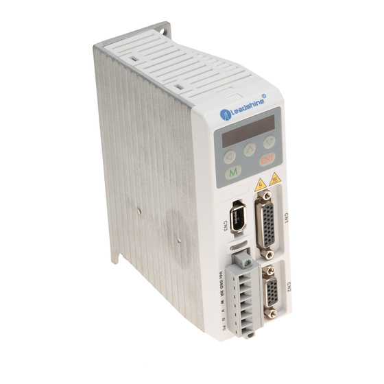
Chapter 1 Introduction 1.1 Product Introduction The ELD5 series AC servo motor &driver is the latest servo system that’s meets all demands for a variety of machines which require high speed, high precision and high performance or which require simplified settings. - Page 8 Connection to Connection to PC controller for configuration Power supply Connection for Connection to encoder motor power 2. Servo motor appearance: 3. Accessory ELD5 series servo driver standard accessories a. user manual b.CN1 connector (DB26) c. CN2 plug (DB15 pin) www.leadshine.com...
-
Page 9: Quick Selection
ELDM 6040V48HL-L5 400w/60mm/48V/3000rpm/1.27Nm/23bit encoder ELDM 6040V48GL-L5 400w/60mm/48V/3000rpm/1.27Nm/23bit encoder/Brake ELDM 6040V60HL-L5 400w/60mm/60V/3000rpm/1.27Nm/23bit encoder ELDM 6040V60GL-L5 400w/60mm/60V/3000rpm/1.27Nm/23bit encoder/Brake “C” means 5000line incremental encoder with serial signal. “E” means 17bit single-turn absolute encoder. “L” means 23 bit multi-turn absolute encoder. www.leadshine.com... -
Page 10: Chapter 2 Installation
Protection IP00(no protection) IP54 level Contact tech@leadshine.com for more technical service . 2.2 Servo Driver Installation Notice Must install in control cabinet with sufficient safeguarding grade. Must install with specified direction and intervals, and ensure good cooling condition. -
Page 11: Installation Space
User Manual for ELD5 Servo (V1.00) Figure 2.1 installation method of driver ELD5-400(U)/ELD5-400(U)Z 2.2.2 Installation Space Reserve enough surrounding space for effective cooling. Figure 2.2 Installation Space for Single Driver www.leadshine.com... -
Page 12: Servo Motor Installation
Motor shaft does not bear the axial load, radial load, otherwise you may damage the motor. Use a flexible with high stiffness designed exclusively for servo application in order to make a radial thrust caused by micro misalignment smaller than the permissible value. Install must be steady, prevent drop from vibrating. www.leadshine.com... -
Page 13: Chapter 3 Wiring
Caution Ground the earth terminal of the motor and driver without fail. The wiring should be connected after servo driver and servo motor installed correctly Contact tech@leadshine.com for more technical service . 3.1 Wiring 3.1.1 Wire Gauge (1)Power supply terminal TB ●... -
Page 14: Position Control Mode
DIR- COM+ A+ 4.7K SRV-ON A- B+ 4.7K B- Encoder signal output 4.7K 12~24Vdc ZEROSPD 4.7K S-RDY Use twisted wire with shield for encoder signal output BRK-OFF Connection for configuration with RS232 COM- Figure 3-1 Positional Control Mode Wiring www.leadshine.com... -
Page 15: Torque /Velocity Control Mode
3.1.3 Torque /Velocity Control Mode DC power supply COM+ 4.7K SRV-ON A+ A- 4.7K B+ B- 4.7K Encoder 12~24Vdc signal output ZEROSPD 4.7K S-RDY Vin+ +10V ~ -10V Vin- analoginput BRK-OFF COM- Connection for configuration with RS232 Figure 3-2 Torque/Velocity Control Mode Wiring www.leadshine.com... -
Page 16: Driver Terminals Function
Digital input signal 5, default value is deviation counter clear SI5-CLR Input input in position mode , low level available in default , max voltage is 24V input Vin+ Input Analog input , voltage input range : -10 - 10V , input resistor 20KΩ Vin- Input www.leadshine.com... -
Page 17: Encoder Input Port-Cn2 Terminal
Hall sensor W- input Hall U- Hall sensor U- input Table 3.3 Encoder Input Port-CN2 Terminal Signal for ELD5-400Z or ELD5-400ZU Signal Name EGND Signal ground Encoder signal +5V for encoder power supply BAT+ Only available for multi-turn absolute encoder BAT- www.leadshine.com... -
Page 18: Communication Port
Signal Detail +24V ~ +60V Power Ground Brake input Motor W Motor V Motor U Shield 3.2.5 Bus connector Signal Detail RS485+ 485data+ RS485- 485 data- Ground Ground RS485+ 485data+ (RJ45) RS485- 485 data- Ground Ground Others 16pin totally www.leadshine.com... -
Page 19: I/O Interface Principle
(3) If the load is inductive loads relays, etc., there must be anti-parallel freewheeling diode across the load. If the freewheeling diode is connected reversely, the servo drive is damaged. www.leadshine.com... -
Page 20: Pulse Input Interface
Pulse symbol Pulse + direction The form of pulse input timing parameter is the following form 3.8 below. The 4 times pulse frequency ≤ 500kH if 2-phase input form is used. Table 3.8 the parameters of pulse input time sequence www.leadshine.com... -
Page 21: Analog Value Input Interface
Figure 3.8 pulse + direction input interface timing (the maximum of pulse frequency : 500KHZ) 3.3.4 Analog Value Input Interface Figure 3-9 Analog Input Interface 3.3.5 Servo Motor Encoder Input Interface Driver side Figure 3-11 Servo Motor optical-electrical Encoder Input Interface www.leadshine.com... -
Page 22: Chapter 4 Parameter
Torque feed forward gain Torque feed forward filter 2nd gain setup Control switching mode Control switching level Control switch hysteresis Gain switching time Positional command filter setup Encoder feedback pulse digital filter setup 【Class 2】 adaptive filter mode setup www.leadshine.com... - Page 23 SI4 input selection SI5 output selection SO1 output selection SO2 output selection SO3 output selection SO4 Analog input 1(AI 1) offset setup Analog input 1(AI 1) filter Analog input 3(AI 3) offset setup Analog input 3(AI 3) filter www.leadshine.com...
- Page 24 Negative direction torque compensation value distance of trial running waiting time of trial running cycling times of trial running 【Class 7】 Current loop gain Factory Current loop integral time setting 02-14 Setting of motor parameter Motor model input Encoder selection www.leadshine.com...
-
Page 25: Parameter Function
User Manual for ELD5 Servo (V1.00) 4.2 Parameter Function Here is the explanation of parameters, you can check them or modify the value using software Protuner or the front panel of driver. Contact tech@leadshine.com for more technical service . 【 】 4.2.1 Class 0... - Page 26 Pr0.04 is smaller than the actual value, the setup unit of the velocity loop gain becomes smaller. Related Command Pulse Rotational Direction Range unit default Pr0.06* control mode Setup Set command pulse input rotate direction, command pulse input type, changing this value will www.leadshine.com...
- Page 27 Set the numerator of division/multiplication operation made according to the command pulse input. Related Range unit default denominator of electronic gear Pr0.10 control mode 1-32767 Set the denominator of division/multiplication operation made according to the command pulse input. Pr0.09 Pr0.10 Command division/multiplication operation www.leadshine.com...
-
Page 28: Analog Input Value
Pr0.12 B-phase Logic CCW Direction Rotation CW Direction Rotation Non-Reversal A phase A phase B phase B phase Reversal A phase A phase B phase B phase Related Range unit default 1st Torque Limit Pr0.13 control mode 0 -500 www.leadshine.com... -
Page 29: Class 1】Gain Adjust
You can set the filter parameters through the loop gain, referring to the following table: Speed Detection Filter Speed Detection Filter Value Cut-off Frequency(Hz) Value Cut-off Frequency(Hz) 2500 2250 2100 2000 1800 1600 1500 1400 1300 1200 1100 1000 www.leadshine.com... -
Page 30: Inertia Ratio
Positional deviation at a constant acceleration/deceleration can be minimized close to 0 by increasing the torque forward gain .this means that positional deviation can be maintained at near 0 over entire operation range while driving in trapezoidal speed pattern under ideal condition www.leadshine.com... - Page 31 Shift to the 2nd gain when the positioning was not completed complete previously with the 1st gain. Return to the 1st gain when the positioning was kept in completed condition previously during delay time with the 2nd gain. Valid for position control. Actual speed is www.leadshine.com...
- Page 32 Positional command filter setup Pr1.35* control mode 0.05us 0 -200 Do filtering for positional command pulse, eliminate the interference of the narrow pulse, over-large setup will influence the input of high frequency positional command pulse, and make more www.leadshine.com...
-
Page 33: Class 2】Vibration Suppression
Notice: Higher the setup, shallower the notch depth and smaller the phase delay you can obtain. Related positional command smoothing Range unit default Pr2.22 control mode filter 0.1ms 0 -32767 Set up the time constant of the1st delay filter in response to the positional command. www.leadshine.com... -
Page 34: Class 3】Velocity/ Torque Control
1-3 and speed command to be selected> selection 1 of selection 2 of internal selection 3 of selection of Setup internal command command speed internal command Speed value speed(INTSPD1) (INTSPD2) speed (INTSPD3) command NO effect 1st speed 2nd speed 3rd speed www.leadshine.com... - Page 35 Pr3.02 gives larger variance to the overall servo system. 3. Pay an extra attention to oscillation caused by larger setup of Pr3.02. Related Range unit default Reversal of speed command input control mode Pr3.03 0 -1 www.leadshine.com...
- Page 36 Acceleration time setup. Also set the time required for the speed command to reach from 1000r/min to 0 r/min, to Pr3.13 Deceleration time setup. Assuming that the target value of the speed command is Vc(r/min), the time required for acceleration/deceleration can be computed from the formula shown below. Acceleration time (ms)=Vc/1000 *Pr3.12 *1ms www.leadshine.com...
- Page 37 When analog speed given value under speed control mode less than zero speed clamp level setup, speed command will set to 0 strongly. Related Range unit default Torque command direction selection Pr3.18 control mode 0 -1 Select the direction positive/negative direction of torque command www.leadshine.com...
-
Page 38: Class 4】I/F Monitor Setting
For parameters which No. have a suffix of “*”,changed contents will be validated when you turn on the Note: control power. 【 】 4.2.5 Class 4 I/F Monitor Setting Related Range unit default Input selection SI1 Pr4.00* control mode 0-00FFFFFFh 00030303h www.leadshine.com... - Page 39 1or Err21.1 I/F input multiple assignment error 2. Related Range unit default Output selection SO1 Pr4.10* control mode 0-00FFFFFFh 00010101h Related Range unit control mode Pr4.11* Output selection SO2 00020202h 0-00FFFFFFh (131586) Related Range unit control mode Output selection SO3 Pr4.12* 00000704h 0-00FFFFFFh (65793) www.leadshine.com...
- Page 40 The signal will turn on when there is no position command, the zero-speed detection signal is ON and the positional deviation is smaller than Pr4.31 [positioning complete range]. The signal will turn on when there is no position command and the positional www.leadshine.com...
- Page 41 Because the speed coincidence detection is associated with 10 r/min hysteresis, actual detection range is as shown below. Speed coincidence output OFF -> ON timing (Pr4.35 -10) r/min www.leadshine.com...
- Page 42 Related Mechanical brake action at running Range unit default control mode Pr4.38 setup 0 -10000 Mechanical brake start delay time setup, mainly used to prevent servo off “galloping “phenomenon. www.leadshine.com...
-
Page 43: Class 5】Extended Setup
Pr5.03 Pr5.02 Pr5.03 For details, refer to Pr0.11 . Related Range unit default Sequence at servo-off control mode Pr5.06 Specify the status during deceleration and after stop, after servo-off. Setup value during deceleration After stop emergency Free-run Free-run Free-run www.leadshine.com... - Page 44 Analog input value Error factor and Positional command Driver serial number reference of history speed Inertia ratio Motor serial number Velocity control command Factor of no-motor Accumulated operation Torque command running time Communication axis Temperature Feedback pulse sum address information www.leadshine.com...
-
Page 45: Class 6】Special Setup
You can set up the command speed used for JOG trial run (torque control). Related Range unit default Pr6.04 JOG trial run command speed control mode r/min 0-500 You can set up the command speed used for JOG trial run (velocity control). www.leadshine.com... - Page 46 Trial run waiting time Pr6.21 control mode 0-30000 1000 The waiting time after running each time in JOG run(position control) Related Range unit default Trial run cycle times Pr6.22 control mode 0-32767 The cycling times of JOG run(position control) www.leadshine.com...
-
Page 47: Chapter 5 Alarm And Processing
Encoder data error ● ● Too large position pulse deviation ● ● ● Too large velocity deviation ● ● ● Over-speed 1 ● ● ● I/F input interface allocation error ● ● I/F input interface function set error ● ● www.leadshine.com... -
Page 48: Alarm Processing Method
Driver inner fault replace the driver with a new one Main Extra Display: “ ” Error code Content: DC bus circuit error Cause Confirmation Solution Vdc/GND under-voltage Check the voltage of Vdc/GND Make sure voltage of Vdc/GND in terminal proper range www.leadshine.com... - Page 49 Modify the parameter Adjust parameter to proper range parameter abnormal setting of control Check control command whether Adjust control command: open command command changes too violently or filter function www.leadshine.com...
- Page 50 Check the load if it is inertia ,increase external regenerative resistor, regenerative resistor . too large or not. improve the capacity of the driver and motor Resistance discharge Increase external regenerative resistor, replace circuit damage the driver with a new one www.leadshine.com...
- Page 51 Enlarge the value of PA_103, Torque limit is too small whether too small or not PA_522 Check acceleration/ deceleration time if it Increase acceleration/ Outside load is too large is too small or not , check motor rotational deceleration time decrease www.leadshine.com...
- Page 52 Main Extra Display: “ ” Error code Content: I/F input interface function set error Cause Confirmation Solution Signal allocation error Check the value of PA_400, PA_401, Assure the value of PA_400, www.leadshine.com...
- Page 53 Main Extra Display: “ ” Error code Content: forced alarm input valid Cause Confirmation Solution Forced-alarm input signal Check forced-alarm input signal Assure input signal wiring correctly has been conducted www.leadshine.com...
-
Page 54: Chapter 6 Display And Operation
Press this key to increase the set value of current flash bit ▼ Down key Press this key to decrease the set value of current flash bit ◄ Left key Press this key to shift to the next digit on the left www.leadshine.com... -
Page 55: Panel Display And Operation
Press ENT to save it and switch to the interface of parameter No. 6.2.2 Driver Operating Data Monitor Table 6.2 Function List of Driver Monitor Serial Data Format Name Specification Display Unit Number (x, y is numerical value) www.leadshine.com... -
Page 56: Positional Command Deviation
Error factor and “Er xxx” d12Err reference of history “m xxx” d13 rn Alarm display Regeneration load factor “rg xxx” d14 r9 “oL xxx” d15 oL Over-load factor “J xxx” d16Jrt Inertia ratio Factor of no-motor “cP xxx” d17 ch running www.leadshine.com... -
Page 57: Communication Axis
“t xxx” Safety condition “xxxxxx” d35 SF monitor Table 6.3 “d17 ch” Motor No Rotate Reason Code Definition Code Display Code Specification Content DC bus under-voltage The Servo-ON input (SRV-ON) is not connected to No entry of Srv-On input COM- www.leadshine.com... -
Page 58: System Parameter Setting Interface
1st position loop gain of 1st velocity loop time constant of 1st velocity loop integration filter of 1st velocity detection time constant of 1st torque filter gain of 2nd position loop gain of 2nd velocity loop www.leadshine.com... - Page 59 2nd notch depth selection Positional command smooth filter Positional command FIR filter Velocity setup internal/external switching Speed command rotational direction selection Speed command input gain Speed command reversal input 1st speed setup 2nd speed setup 3rd speed setup 4th speed setup www.leadshine.com...
- Page 60 SO 3 output selection SO 4 output selection Analog input 1(AI 1) offset setup Analog input 1(AI 1) filter Analog input 3(AI 3) offset setup Analog input 3(AI 3) filter Positioning complete range Positioning complete output setup INP hold time Zero-speed www.leadshine.com...
-
Page 61: Auxiliary Function
Name Specification Display Code Operation Flow AF_jog Trial run Please refer to the chapter of“trial run” 1. press ENT to enter operation, Initialization display“ ”。 AF_InI parameter 2.press ▲ once to display “ ”, indicated initialization; after finishing it, www.leadshine.com... -
Page 62: Saving Parameter
6.2.5 Saving parameter Operation procedure: 1. press M to select EEPROM writing mode, display “ ”; 2. Press ENT to enter into writing mode operation: 3. Press and hold ▲, display LED from” ” to” ”, then it become” ”, www.leadshine.com... -
Page 63: Abnormal Alarm
6.2.6 Abnormal Alarm The front panel will automatically enter the abnormal alarm display mode if driver error occurs while it displays the corresponding error code. Please refer to Chapter 5 of alarm processing about the detail of error code. www.leadshine.com... -
Page 64: Chapter 7 Trial Run
Note: there are two kinds of trial run : trial run without load and trial run with load . The user need to test the driver without load for safety first. Contact tech@leadshine.com for more technical service . 7.1 Inspection Before trial Run 7.1.1 Inspection on wiring... -
Page 65: Timing Chart On Power-Up
Use this built-in brake for “holding” purpose only. That is to hold the stalling status. For the brake release timing at power-on ,or braking timing at servo-off/servo-alarm while the motor is in motion ,refer to chapter 7.1.2 timing chart on power-up. You can follow the diagram about the wiring below : www.leadshine.com... -
Page 66: Trial Run
2. Enter EEPROM writing mode, and save the value of modified parameters ; 3. The driver need to restart after the value is written successfully; 4. Enter auxiliary function mode, and go to “ "sub-menu; 5. Press ENT once, and display "; www.leadshine.com... -
Page 67: Position Control
1). If the driver is enabled with external signal , pr400 should be set to 303 , and connection of CN1 should be set as following : DC12-24V COM+ Srv_on pulse PUL+ PUL- direction Figure 7-3 Control Terminal CN1 Signal Wiring in Position Control Mode with external servo_on signal www.leadshine.com... -
Page 68: Velocity Control
Speed setting input reversal PA_303 User-specified Analog input I(AI1) offset setup 0.359mv PA_422 User-specified PA_423 Analog input I(AI1) filter User-specified 0.01ms PA_400 SI1 input selection Srv_on hex:0300 SI2 input selection ZeroSpd hex:1100 PA_401 SI3 input selection IntSpd1 hex:0E00 PA_402 www.leadshine.com... -
Page 69: Torque Control
If the motor does not run correctly, refer to the Factor of No-Motor running in data monitor mode (" " ). 7.2.4 Torque Control Notice : You must do inspection before torque control test run. Table 7.6 Parameter Setup of Torque Control www.leadshine.com... -
Page 70: Automatic Control Mode Run
7.3 Automatic Control Mode Run 7.3.1 Operation Mode Selection ELD5 series Low-voltage AC servo drives support the position, speed, torque three basic modes of operation, and can switch freely between the three basic modes of operation by switch or modify parameters. -
Page 71: Position Mode
1, Switch the driver to Servo Off status. 2, Modify the corresponding parameters of control mode to EEPROM. Turn off/on the power to make the new mode works after setup completed. 7.3.2 Position Mode The driver is widely used for precise positioning in position control mode. www.leadshine.com... - Page 72 The positional commands of the following 3 types (pulse train) are available. ◆A, B phase pulse ◆Positive direction pulse/negative direction pulse ◆Pulse + sign Please set the pulse configuration and pulse counting method based on the specification and configuration of installation of the host controller. www.leadshine.com...
- Page 73 The completion of positioning can be verified by the positioning complete output (INP).When the absolute value of the positional deviation counter at the position control is equal to or below the positioning complete Range by the parameter, the output is ON. Presence and absence of positional command can be specified as www.leadshine.com...
-
Page 74: Velocity Mode
7.3.3 Velocity Mode The driver is widely used for accuracy speed control in velocity control mode. You can control the speed according to the analog speed command from the host controller or the speed command set in servo driver. www.leadshine.com... - Page 75 Parameter Name Setup method PA_300 Velocity setup internal/external switching PA_301 Speed command rotational direction selection PA_302 Speed command input gain Please refer to chapter 4 PA_303 Speed command reversal input PA_422 Analog input offset setup PA_423 Analog input filter www.leadshine.com...
- Page 76 This function controls the speed by adding acceleration or deceleration instruction in the driver to the input speed command. Using this function, you can use the soft start when inputting stepwise speed command or when using internal speed setup. You can also use S shaped acceleration/deceleration function to minimize shock due to change in speed. www.leadshine.com...
-
Page 77: Torque Mode
4.7K B+ B- 4.7K Encoder 12~24Vdc signal output ZEROSPD 4.7K S-RDY Vin+ +10V ~ -10V Vin- analoginput BRK-OFF COM- Connection for configuration with RS232 Figure 7-8 Torque Mode Typical External Wiring Diagram Relevant parameters setup of torque control mode www.leadshine.com... - Page 78 Please refer to chapter 4 PA_422 Analog input offset setup PA_423 Analog input filter 3. SI/SO function set For details of SI input function, refer to PA_400 – PA409. For details of SO output function, refer to PA_410 – PA415. www.leadshine.com...
-
Page 79: Chapter 8 Product Specification
User Manual for ELD5 Servo (V1.00) Chapter 8 Product Specification Notice Servo drive must be matched with relevant servo motor, Contact tech@leadshine.com for more technical service. 8.1 Driver Technical Specification Table 8.1 Driver Specification Type ELD5-400/ELD5-400U ELD5-400Z/ELD5-400UZ Rated output power... -
Page 80: Accessory Selection
× mechanical reduction ratio. 【Note 】If the electronic gear ratio of G is not 1, gear ratio division may have the remainder, then there will be position deviation existed, the maximum deviation is the minimum of rotation ( minimum resolution ). www.leadshine.com... -
Page 81: Appendix
Tel: 86-755-2641-8447 86-755-2641-8774 (for Asia, Australia, Africa areas) 86-755-2665-5136 (for America areas) 86-755-8654-2465 (for Europe areas) Fax: 86-755-2640-2718 Email: tech@leadshine.com (for All) Sales Hot Line Tel: 86-755-2641-7674 (for Asia, Australia, Africa areas) 86-755-2640-9254 (for Europe areas) 86-755-2641-7617 (for America areas) Email: sales@leadshine.com...
Need help?
Do you have a question about the ELD5 Series and is the answer not in the manual?
Questions and answers