
Related Manuals for GYS ERGO LIFT 650


Summary of Contents for GYS ERGO LIFT 650
- Page 1 User manual ERGO LIFT 650 Operation and maintenance manual 73502-V4-01/09/2020 www.gys.f r...
- Page 2 ERGO LIFT 650 Safety and functional check In order to guarantee that your ERGO LIFT 650 lift has been manufactured in strict compliance with safety standards, here are the results of the tests that your product has been subjected to before shipment (please always keep this manual provided when you purchased the equipment).
-
Page 3: Background Information
ERGO LIFT 650 Thank you for choosing GYS In order to obtain maximum satisfaction from your ERGO LIFT 650 and for your safety, please read these operating instructions carefully before first use and keep them in a safe place for future reference. - Page 4 ERGO LIFT 650 This equipment is delivered with a 16 A CEE7/7 type plug and must only be used on a single-phase 230 V (50Hz) electrical installation. Never lift loads on sloping ground (>3°). The floor must be flat and strong enough to prevent the ERGO LIFT from sinking under the weight of the load (35kg/cm²).
- Page 5 Do not use the goods and contact your dealer directly. Failing this, a reservation must be made to the carrier. Under no circumstances can GYS be held responsible. Unloading can be done with a forklift or hand pallet truck as soon as the pallet is placed on the floor. Wear gloves and safety shoes.
- Page 6 ERGO LIFT 650 motor should stop automatically and it should no longer be possible to lift. If this is not the case, please refer to ANOMALIES, CAUSES, REMEDIES on page 14. 6- Retrieve and assemble the manoeuvring drawbar and attach it to the hydraulic unit to be able to move it more easily.
-
Page 7: Individual Protection
ERGO LIFT 650 INDIVIDUAL PROTECTION The operator must be equipped in accordance with the occupational risk prevention standards applicable in his/her country and must adopt all necessary measures to maintain safety at his/her workstation. During manoeuvres, the operator must ensure his own safety and that of the people and objects around him. The operator must take into consideration all the recommendations quoted in this manual. - Page 8 ERGO LIFT 650 Step 5: Using the remote control: Max position Manoeuvring Limit switch sensor STOP Going Drawbar Down support Min position Press the up button or "↑" to raise the lift. As long as the button is held down, the lift will rise until a double beep sounds (end position reached by the sensor).
- Page 9 ERGO LIFT 650 Hydraulic power pack Wheel + Once the area has been determined, place the lift and carry out the reverse manoeuvre without forgetting to remove the 2 wheels and the pins and store them on the support at the level of the manoeuvring tiller.
- Page 10 ERGO LIFT 650 Then spread the arms completely apart and put the rubber pads on them. Position the skids below the grip points provided by the car manufacturers. Once the support arm has been correctly positioned, check that it is correctly in place and locked by simply moving it from right to left.
-
Page 11: Controls And Maintenance
ERGO LIFT 650 Before lifting a vehicle, make sure the handbrake is released and the vehicle is left in neutral. The wheels when taking off from the ground need to be free as when descending. Otherwise, there is a risk that the load will slip on the rubber pads and lead to a dangerous and unstable situation. -
Page 12: Maintenance Table
ERGO LIFT 650 MAINTENANCE TABLE Maintenance Task Remarks intervals Refer to "Check and Lubrication Check, clean and lubricate all moving parts, especially the joints. Point (page 12)". Check that the locking system of the 4 load- bearing elements is working properly and that the stops are present. - Page 13 ERGO LIFT 650 CHECK POINT AND LUBRICATION All joints are provided with small holes for lubrication with SAE 90 type oil (fluid oil). The 20 lubrication points are listed below (1). One drop per hole is enough! Check the tightness of the individual screws at the joints. The lock washer must always remain flat (2).
- Page 14 ERGO LIFT 650 Functional test of the limit sensor: Press the "Up" or "↑" button until a double beep is heard and the lift stops automatically. STOP 55,5 / 56,5cm Going Down Limit switch sensor The distance from the ground to the crossbar should be between 55.5cm and 56.5cm. If the reached height is lower or higher, an adjustment of the sensor rod must be carried out.
-
Page 15: Troubleshooting
ERGO LIFT 650 TROUBLESHOOTING The table below shows the anomalies that can be observed when using the ERGO LIFT. If the problem is not listed in the table below, stop using the tool and immediately contact your dealer or the manufacturer for instructions. -
Page 16: Warranty Conditions
ERGO LIFT 650 audible warning must be heard to indicate that the lift is descending. The lift descends very Both coils are activated Each solenoid valve is equipped with slowly without using the manual activation in the event of a remote control. - Page 17 ERGO LIFT 650 DIMENSIONS...
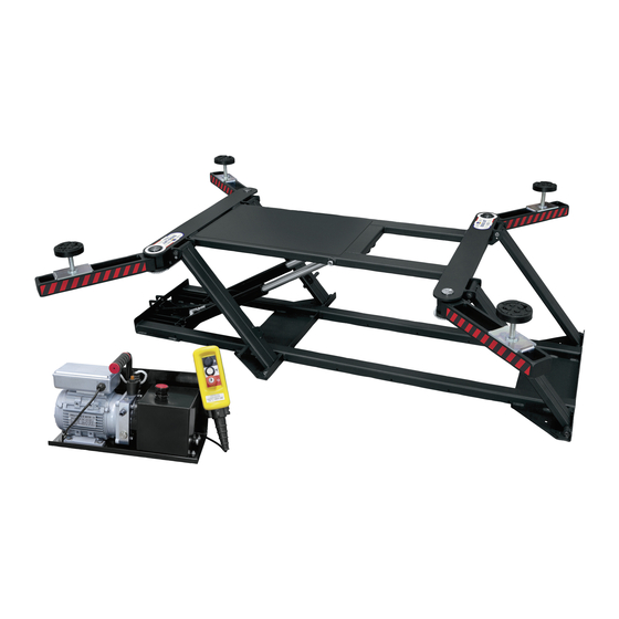
- Page 18 ERGO LIFT 650 1 Manoeuvring drawbar 2 Hydraulic power pack FEATURES Maximum allowed load 2,000 kg Type of vehicle allowed Tourism vehicle Electrical installation 230V AC1 ~ 50Hz Power 0,75Kw Oil tank capacity Noise level <70 dB (A) Rising time Approx.
-
Page 19: Spare Parts
ERGO LIFT 650 NAMEPLATE The technical nameplate is located on the rear of the hydraulic unit where you will find the serial number of the product, the year and month of manufacture. The tracking number can also be found in duplicate on the lift and in this manual on page 1. - Page 20 ERGO LIFT 650 N° Ref. Designation 93607ST Phosphated skate support 55239 Round rubber pad 119 x 31 93610ST Original phosphate-plated lifting table shoe 93613RI Lift table arm Red 3020 93792ST Phosphated lifting table arm axis 43267 Axis brake for tumbler Ø30 raw steel din 6799...
-
Page 21: Product Information
Support plate for hydraulic power pack 92215 lifting table Grey 7021 71380 Wheel fixing washer diameter=12 Wheel Diameter=125mm Axis=12mm 71370 Width=35mm caps black Gys 1-Angle 1-Point Shoe (40x40x30 TPE/TPR 56061 80sh) 71814 Complete hydraulic unit PRODUCT INFORMATION Ref. 75716 Ref. 75714 Ref. - Page 22 ERGO LIFT 650 Hydraulic circuit Electric circuit...
- Page 23 ERGO LIFT 650 REGULAR SAFETY INSPECTION Description of the product ERGO LIFT 650 Serial number Verification phase Remarks Presence of the technical panel on the hydraulic unit with the serial number of the lift Presence of the maximum load of 2000kg on the lift with the serial number.
-
Page 24: Maintenance Log
ERGO LIFT 650 MAINTENANCE LOG Purchase date:___________started by: ___________________ on the _____/_____/20______ Archiving of monthly and annual checks: tick the boxes to certify periodic checks. Year____________ Months January February March April June July August September October November December Controled Year____________...
Need help?
Do you have a question about the ERGO LIFT 650 and is the answer not in the manual?
Questions and answers