Middleby Marshall Tandem PS360 Series Owner's Operating & Installation Manual
Hide thumbs
Also See for Tandem PS360 Series:
- Owner's operating & installation manual (32 pages) ,
- Owner's operating and installation manual (4 pages) ,
- Technical & service manual (182 pages)

Related Manuals for Middleby Marshall Tandem PS360 Series


Summary of Contents for Middleby Marshall Tandem PS360 Series
- Page 1 All manuals and user guides at all-guides.com A MIDDLEBY COMPANY owner's operating & installation manual SERIES PS360/PS360WB TANDEM GAS OVEN MODELS © 1999 Middleby Marshall Inc.
- Page 2 All manuals and user guides at all-guides.com NOTICE: This Operating and Installation Manual should be given to the user. The operator of the oven should be familiar with the functions and operation of the oven. This manual must be kept in a prominent, easily reachable location near the oven. The oven has a combustion system suitable for use with all natural gases and can be converted by a qualified service agent for use with liquified gas.
- Page 3 NO QUIBBLE LIMITED WARRANTY OVEN LIMITED WARRANTY (U.S.A. ONLY) (Non U.S.A.) MIDDLEBY MARSHALL, HEREINAFTER REFERRED TO The seller warrants equipment manufactured by it to be free from defects in material and workmanship for which it is AS THE SELLER, WARRANTS EQUIPMENT MANUFAC- responsible.
- Page 4 All manuals and user guides at all-guides.com TABLE OF CONTENTS page page SECTION 1 - DESCRIPTION ..........1-1 SECTION 3 - OPERATION ............ 3-1 SECTION 4 - MAINTENANCE ..........4-1 SECTION 2 - INSTALLATION ..........2-1 SECTION 5 - ELECTRICAL SCHEMATICS ......4-1...
- Page 5 All manuals and user guides at all-guides.com SECTION 1 DESCRIPTION SECTION 1 DESCRIPTION I. OVEN SPECIFICATIONS A. PHYSICAL SPECIFICATIONS Tandem Double Tandem Tri Tandem Quad Tandem PS360 PS360WB PS360 PS360WB PS360 PS360WB PS360 PS360WB Dimensions: Recommended Minimum Clearances: B. GENERAL SPECIFICATIONS (per oven section) PS360 PS360WB C.
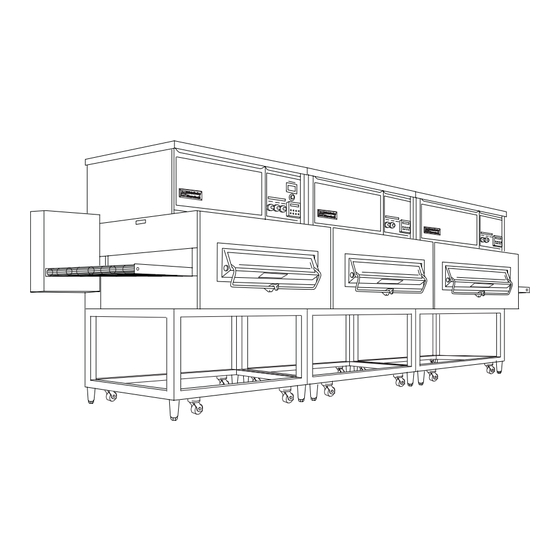
- Page 6 All manuals and user guides at all-guides.com SECTION 1 DESCRIPTION II. OVEN USES III. OVEN COMPONENTS Figure 1-1 - Oven Components A. Conveyor Drive Motor: End Panels: B. Air Fingers: J. Conveyor End Stop (not present on ovens with C. Conveyor: heavy-duty conveyor): D.
- Page 7 All manuals and user guides at all-guides.com SECTION 2 INSTALLATION SECTION 2 INSTALLATION WARNING Do not obstruct the flow of combustion and ventilation air to and from your oven. There must be no obstructions around or underneath the oven. CAUTION For additional installation information, refer to the PS360 Pre-Installation Procedures Manual (Middleby Marshall P/N 88210-0024) or contact your local Authorized Service Agent.
- Page 8 All manuals and user guides at all-guides.com SECTION 2 INSTALLATION I. INSTALLATION KIT Fig. 2-1 - Installation Kit Item Part # Description Tandem Double Tandem Tri Tandem Quad Tandem II. TRANSITION CHAMBER COMPONENTS (Quad Tandem Ovens Only) Qty. Part # Description Qty.
- Page 9 All manuals and user guides at all-guides.com SECTION 2 INSTALLATION III. VENTILATION SYSTEM IMPORTANT Where national or local codes require the installation of fire suppression equipment or other supplementary equipment, DO NOT mount the equip- ment directly to the oven. MOUNTING SUCH EQUIPMENT ON THE OVEN MAY: •...
- Page 10 All manuals and user guides at all-guides.com IV. THERMOCOUPLE INSTALLATION Figure 2-3 Thermocouple Installation Locations Figure 2-4 Placing the Thermocouple Leads Figure 2-5 Thermocouple Lead Connections...
- Page 11 All manuals and user guides at all-guides.com V. ASSEMBLY A. OVEN STAND Figure 2-6 Exploded View - Oven Stand B. JOINING THE OVEN BODIES on all mating ends Figure 2-7 Oven Positioning and Alignment LEFT OVEN RIGHT OVEN NOTE:...
- Page 12 All manuals and user guides at all-guides.com SECTION 2 INSTALLATION Figure 2-8 - Cooling Fan Removal Figure 2-9 - Bolts and Spacers Figure 2-10 - Aligning the Sections...
- Page 13 All manuals and user guides at all-guides.com SECTION 2 INSTALLATION Figure 2-11 - Trim Strip Installation Figure 2-12 C. INSTALLING THE CENTER TRANSITION Support Channel Installation - Lower Oven Figure 2-13 Support Channel Installation - Upper Oven...
- Page 14 All manuals and user guides at all-guides.com SECTION 2 INSTALLATION Figure 2-14 Support Brackets, Lower Oven Figure 2-15 Support Brackets, Upper Oven Figure 2-16 Floor Panel Installation Figure 2-17 Installing the Frame...
- Page 15 All manuals and user guides at all-guides.com SECTION 2 INSTALLATION D. INSTALLING THE CONVEYOR FRAME AND BELT Figure 2-18 Tandem and Double Tandem Conveyor Installation Figure 2-19 Tri Tandem Conveyor Installation Figure 2-20 Quad Tandem Conveyor Installation...
- Page 16 All manuals and user guides at all-guides.com SECTION 2 INSTALLATION Figure 2-21 - Conveyor Link Orientation Figure 2-22 - Inside Master Links Figure 2-23 Outside Master Links 2-10...
- Page 17 All manuals and user guides at all-guides.com SECTION 2 INSTALLATION Figure 2-24 - Transition Section Final Assembly Figure 2-25 Conveyor Motor and Drive Chain Assembly 2-11...
- Page 18 All manuals and user guides at all-guides.com SECTION 2 INSTALLATION VI. ELECTRICAL SUPPLY WARNING CAUTION NOTE: The electric supply installation must satisfy the requirements of the appropriate statutory authority, such as the National Electrical Code (NEC), ANSI/NFPA70, (U.S.A.); the Canadian Electrical Code, CSA C22.2; the CAUTION Australian Code AG601;...
- Page 19 All manuals and user guides at all-guides.com SECTION 2 INSTALLATION VII.GAS SUPPLY A. CONNECTION CAUTION DURING PRESSURE TESTING NOTE ONE OF THE FOLLOWING: 1. The oven and its individual shutoff valve must be disconnected from the gas supply piping system during any pressure testing of that system at test pressure in excess of 1/2 psi (3.45 kPa).
- Page 20 All manuals and user guides at all-guides.com SECTION 2 INSTALLATION B. GAS CONVERSION WARNING: NOTE: In Canada, to conform with the CAN/CGA-B149.2 propane installation code, the oven must be ordered propane. It may not be converted in the field. Figure 2-28 Flexible Gas Hose Installation Figure 2-29 Gas Burner and Piping Assembly...
- Page 21 All manuals and user guides at all-guides.com SECTION 3 OPERATION SECTION 3 OPERATION IMPORTANT THESE OVENS ARE INTENDED FOR PROFESSIONAL USE ONLY. THE OVENS MAY ONLY BE OPERATED BY QUALIFIED PERSONNEL. I. LOCATION AND DESCRIPTION OF CONTROLS Tandem and Tri Tandem and Quad Tandem Ovens Double Tandem Ovens Fig.
- Page 22 All manuals and user guides at all-guides.com SECTION 3 OPERATION II. NORMAL OPERATION - STEP-BY-STEP A. DAILY STARTUP PROCEDURE , wait for (Optional) , wait for B. DAILY SHUTDOWN PROCEDURE , wait for CAUTION The burner will not operate and gas will not flow through the burner without electric power.
- Page 23 All manuals and user guides at all-guides.com SECTION 3 OPERATION III. QUICK REFERENCE: CALCULATING THE BAKE TIME Fig. 3-2 Fig. 3-3 Begin timing End timing IV. QUICK REFERENCE: DIGITAL TEMPERATURE CONTROLLER HEAT ON Light Display SP LOCK Light SET POINT Light OVERTEMP Light ACTUAL TEMP Light Temperature Key...
- Page 24 All manuals and user guides at all-guides.com SECTION 3 OPERATION V. QUICK REFERENCE: TROUBLESHOOTING light is lit, food product is undercooked Oven will not turn on at all Oven shuts down shortly after it is turned on appears in display, oven is not heating Oven will not heat Oven is operating, but...
- Page 25 All manuals and user guides at all-guides.com SECTION 4 MAINTENANCE SECTION 4 MAINTENANCE WARNING WARNING CAUTION NOTE NOTE...
- Page 26 All manuals and user guides at all-guides.com SECTION 4 MAINTENANCE I. MAINTENANCE - DAILY Figure 4-1 - Cooling Fan Locations CAUTION Figure 4-2 Crumb Pans...
- Page 27 All manuals and user guides at all-guides.com SECTION 4 MAINTENANCE II. MAINTENANCE - MONTHLY Figure 4-3 - Removing Fingers and Plates in reverse T1 T2 T3 T4 T5 T6 B1 B2 B3 B4 B5 B6 Figure 4-4 - Disassembling the Air Fingers Manifold Inner plate Outer Plate...
- Page 28 All manuals and user guides at all-guides.com SECTION 4 MAINTENANCE III. MAINTENANCE - EVERY 3 MONTHS IV. MAINTENANCE - EVERY 6 MONTHS NOTES:...
- Page 29 All manuals and user guides at all-guides.com I. ELECTRICAL WIRING DIAGRAM PS360/PS360WB TANDEM AND DOUBLE TANDEM OVENS...
- Page 30 All manuals and user guides at all-guides.com II. ELECTRICAL WIRING DIAGRAM PS360/PS360WB TRI TANDEM AND QUAD TANDEM OVENS...
- Page 31 All manuals and user guides at all-guides.com SECTION 5 ELECTRICAL SCHEMATICS NOTES:...
- Page 32 All manuals and user guides at all-guides.com SECTION 5 ELECTRICAL SCHEMATICS A MIDDLEBY COMPANY Middleby Corp 24-Hour Service Hotline 1-800-238-8444 www.middleby.com...
Need help?
Do you have a question about the Tandem PS360 Series and is the answer not in the manual?
Questions and answers