
Related Manuals for Festo CDSA-D1-VX


Summary of Contents for Festo CDSA-D1-VX
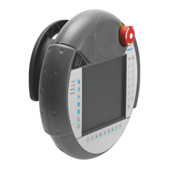
- Page 1 Teach pendant Description Assembly and installation Type CDSA-D1-VX Description 560 334 en 1001a [751 492]...
- Page 3 Edition _____________________________________________________________ en 1001a Description ____________________________________________ Festo GDCP-CDSA-SY-EN Order no. ____________________________________________________________ 560 334 (Festo AG & Co KG., D-73726 Esslingen, 2009) Internet: http://www.festo.com E-mail: service_international@festo.com The copying, distribution and utilization of this document as well as the communication of its contents to others without expressed authorization is prohibited. Offenders will be held liable for compensation of damages.
- Page 4 Index of revisions Author: Name of manual: GDCP-CDSA-SY-EN File name: File saved at: Consec. no. Description Index of revisions Date of amendment Produced: 0805NH 18.08.2008 Update MRL 1001a 16.12.2009 Festo GDCP-CDSA-SY-EN 1001a...
-
Page 5: Table Of Contents
Panic actuation ..................26 5.2 Touch-sensitive keypad ................... 28 5.3 On-the-spot diagnosis ..................... 29 5.3.1 LED diagnostis ..................29 5.4 Display ........................29 Commissioning ....................... 31 6.1 Concluding operation ....................31 6.1.1 Disconnecting the teach pendant ............31 Festo GDCP-CDSA-SY-EN 1001a... - Page 6 Contents Technical specifications CDSA ................32 A.1 General technical specifications ................32 A.2 Technical specifications of the connection terminals ..........35 B. Transport conditions ....................36 Notes on disposal ....................37 Festo GDCP-CDSA-SY-EN 1001a...
-
Page 7: General Information
Teach pendants with a red and yellow EMERGENCY STOP switch, which are not connected to a machine, must be kept out of sight so that they cannot be confused with functioning devices in an emer- gency case. Festo GDCP-CDSA-SY-EN 1001a... -
Page 8: Scope Of Delivery
Additionally required Optional CDSA Teach pendant Brief description CAMI PlugIn housing CAMI-C CAFM Wall fastening CAFM-D1-W CAFB Bridge plug for CDSA NESC C-D1 Cable on teach pendant NECC-L1G11-C1 Socket strip for PlugIn housing Tab. 1.1: Available components Festo GDCP-CDSA-SY-EN 1001a... -
Page 9: General Safety Precautions
Commands for states which bring danger cannot be initiated with a permission button alone. A second starting command is necesary here (button on teach pendant). Only the person who operates the permission button may be present in the danger zone. Festo GDCP-CDSA-SY-EN 1001a... -
Page 10: General Instructions
Service Please consult your local Festo repair service or write to the following e-mail address if you have any technical problems: service_international@festo.com Festo GDCP-CDSA-SY-EN 1001a... -
Page 11: Important User Instructions
Caution The teach pendant is sensitive to electrostatic charges when the connection shaft is open. Electrostatically sensitive devices: Incorrect handling can result in damage to components. Festo GDCP-CDSA-SY-EN 1001a... -
Page 12: Mechanical Installation
III as per EN 1131-2 and EN 50178. The following must be noted in this regard: All voltages saved in the PlugIn housing or in the teach pendant must be low safety voltages and therefore isolated from the low voltage network with a safety transformer or similar. Festo GDCP-CDSA-SY-EN 1001a... -
Page 13: Dimensions
3. Mechanical installation 3.1.1 Dimensions Fig. 3.2: Dimensions of the PlugIn housing Festo GDCP-CDSA-SY-EN 1001a... -
Page 14: Drilling Jig
3. Mechanical installation 3.1.2 Drilling jig Festo GDCP-CDSA-SY-EN 1001a... -
Page 15: Electrical Installation
2 Multi-axis controller CMXR-C1 6 Cable NESC-C-D1-x-C1 3 Ethernet cable (crossover) / 7 Teach pendant CDSA Ethernet cable with switch 8 Wall fastening CAFM-D1-W 4 PlugIn box CAMI-C Fig. 4.1: Connecting the teach pendant to the multi-axis controller CMXR Festo GDCP-CDSA-SY-EN 1001a... - Page 16 4. Electrical installation CDSA NESC CAMI-C Fig. 4.2: Connection diagram overall view Festo GDCP-CDSA-SY-EN 1001a...
- Page 17 -> Permission button, circuit 2, pos. green -> Permission button, circuit 2, neg. grey -> not used n.c. not used n.c. not used purple -> blue -> white -> orange -> -> Tab. 4.1: Signal description NESC Festo GDCP-CDSA-SY-EN 1001a...
-
Page 18: Teach Pendant Cdsa
Lay the teach pendant CDSA with the display downwards on a flat, clean surface so that the teach pendant or its operating elements are not damaged (e.g. soft ESD mat). Open the cover with a Phillips screwdriver size 2. Festo GDCP-CDSA-SY-EN 1001a... -
Page 19: Ethernet Cable Exit
2. Cables must not be squashed. 3. The connection shaft cover must be screwed into place again with all six screws (tightening torque: 0.4 to 0.5 Nm). Only in this way will the relevant protection class be guaranteed. Festo GDCP-CDSA-SY-EN 1001a... -
Page 20: Connecting Cable Nesc-C-D1-X-C1
The connecting cable is resistant to water, cleaning agents (alcohol and tensides), oils, cutting oils (drilling oils), greases and lubricants. Connection cable: cross section: AWG 24 (0.24 mm²) material: zinc-coated copper strands conductor resistance: ≤ 90 Ω/km (≤ 145 ohm/mile) Fig. 4.6: Connecting cable NESC-C-D1-x-C1 Festo GDCP-CDSA-SY-EN 1001a... -
Page 21: Supply Voltage
All supply current circuits to the teach pendant must be fused with maximum 3.15 A. Please note When planning the supply voltage, take into account the voltage drop on the NESC-C-D1-x-C1 connecting cable. The supply voltage specification applies at the terminal strip of the teach pendant. Festo GDCP-CDSA-SY-EN 1001a... -
Page 22: Plugin Housing Cami-C
Permission button, circuit 1, pos. ENABLE_ED1- Permission button, circuit 1, neg. ENABLE_ED2+ Permission button, circuit 2, pos. ENABLE_ED2- Permission button, circuit 2, neg. not used Not used Tab. 4.2: Signals and connections on plug S2 of the PlugIn housing CAMI-C Festo GDCP-CDSA-SY-EN 1001a... -
Page 23: Ethernet
Ethernet interface RJ45 socket on the controller PlugIn housing Tab. 4.3: Ethernet signals and connections 4.3.2 Bridge plug The bridge plug serves for bridging the emergency stop circuit when the teach pendant is disconnected. Fig. 4.8: Bridge plug Festo GDCP-CDSA-SY-EN 1001a... -
Page 24: Operating Elements Of The Teach Pendant
Please note After any severe shock to the device (e.g. due to dropping), you must check the EMERGENCY STOP switch to make sure that it still functions. Festo GDCP-CDSA-SY-EN 1001a... -
Page 25: Setting Up The Permission Button
The outputs of both circuits are protected against short circuit and overload. 1 Permission button Fig. 5.2: Permission button Method of operation The actuating element consists of two symmetrically arranged rocker buttons, the position of which is ascertained by electric sensors and passed onto the evaluation electronics. Festo GDCP-CDSA-SY-EN 1001a... -
Page 26: Panic Actuation
Standard EN 60204-1:1997 specifies that the permission device must be connected to a stop of category 0 or 1, i.e. that the energy must be switched off. Festo GDCP-CDSA-SY-EN 1001a... - Page 27 5. Operating elements of the teach pendant Fig. 5.3: Circuitry of the permission button on the PlugIn housing Festo GDCP-CDSA-SY-EN 1001a...
-
Page 28: Touch-Sensitive Keypad
The length of the period must be selected according to activity demands. Touch-sensitive keypad Keypad assignment The keypad is divided into 2 function groups: 1 Buttons for the jogging mode 2 Buttons for the function selection Fig. 5.4: Touch-sensitive keypad for DCSA teach pendant Festo GDCP-CDSA-SY-EN 1001a... -
Page 29: On-The-Spot Diagnosis
If new calibration should be necessary, this can take place via the "Setup menu". The necessary procedure is described in the documentation GDCP-CDSA-SW. Please note The touch screen should preferably be operated with the touch pin. Please note Sharp objects will damage the touch screen. Festo GDCP-CDSA-SY-EN 1001a... - Page 30 5. Operating elements of the teach pendant 1 Touch pin 2 Touch screen Fig. 5.6: Display Festo GDCP-CDSA-SY-EN 1001a...
-
Page 31: Commissioning
When the bridge plug is inserted the EMERGENCY STOP status can be quitted and the work continued. Caution With a disconnected teach pendant the EMERGENCY STOP switch is no longer active. Controllers with a non-active EMERGENCY STOP switch must therefore be removed. Festo GDCP-CDSA-SY-EN 1001a... -
Page 32: Technical Specifications Cdsa
5 to 95 % Vibration resistance (IEC 60068-2-6) 10 Hz ≤ f < 57 Hz with 0.15 mm 9 Hz ≤ f < 150 Hz with 2 g Shock resistance 25 g / 11 ms (IEC 60068-2-27) Festo GDCP-CDSA-SY-EN 1001a... - Page 33 USB Host / USB Client Operating system VxWorks EMERGENCY STOP buttons Nominal voltage 24 V DC Minimum current 10 mA (per contact) Maximum current loading 1000 mA (per contact) Utilisation category DC13 (as per IEC 60947-5-1) 100000 Festo GDCP-CDSA-SY-EN 1001a...
- Page 34 20 N typical Specifications on EN ISO 13849-1 Category PL (Performance Level) Tp (ProofTest interval) 20 years MTTFd (Mean Time To Failure) 78 years PFHd (Probability of Failure per 1,57 x 10 / 1,35 x 10 Hour) Festo GDCP-CDSA-SY-EN 1001a...
-
Page 35: Technical Specifications Of The Connection Terminals
Insulation-stripping length [mm²] Tab. A.1: PHOENIX plug terminal strips on the PlugIn housing Please note Note the connection ability of the terminal strips when selecting the connecting cable. A multi-conductor connection (2 conductors in one terminal) is not permitted. Festo GDCP-CDSA-SY-EN 1001a... -
Page 36: Transport Conditions
In order that the controller is not damaged during further or return transport, the following transport conditions must be observed: Always use the original packing for transport. The ambient conditions for the device (see chapter "Technical specifications") must also be observed during transport. Festo GDCP-CDSA-SY-EN 1001a... -
Page 37: Notes On Disposal
C. Notes on disposal Notes on disposal Observe national and local regulations concerning the disposal of electronic components. Festo GDCP-CDSA-SY-EN 1001a... - Page 38 C. Notes on disposal Festo GDCP-CDSA-SY-EN 1001a...
Need help?
Do you have a question about the CDSA-D1-VX and is the answer not in the manual?
Questions and answers