Table of Contents
Advertisement
Quick Links
Owners Manual
Electric Drive Supplement
Head Office:
P.O. Box 2018
Hilton Highway, Washdyke
Timaru, New Zealand
Telephone (03) 688 2029
Facsimile (03) 688 2821
Renovator Mk4
Australian Branch:
4B Silverton Close
Laverton North 3026
Melbourne, Australia
Telephone (03) 9314-9666
Facsimile (03) 9314-6810
Pt. No. 67437
Issue 0716
Advertisement
Table of Contents

Related Manuals for Duncan Renovator Mk4


Summary of Contents for Duncan Renovator Mk4
- Page 1 Owners Manual Renovator Mk4 Electric Drive Supplement Head Office: Australian Branch: P.O. Box 2018 4B Silverton Close Hilton Highway, Washdyke Laverton North 3026 Timaru, New Zealand Melbourne, Australia Pt. No. 67437 Telephone (03) 688 2029 Telephone (03) 9314-9666 Issue 0716...
- Page 3 Renovator Mk4 Electric Drive Contents Page Introduction ........
- Page 4 Clough Agriculture reserves the right to make subsequent changes The Owner’s Manual to the machine, where necessary, Your new Duncan Renovator Mk4 will give long and efficient without notification. service if given normal care and operated properly. The Company will not be This owner’s manual is provided so that you can become...
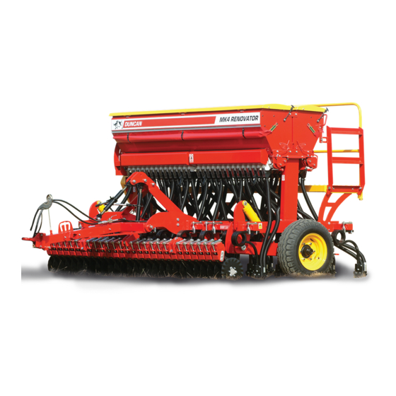
- Page 5 Renovator Mk4 Description of Machine The Duncan ‘Mk4 Renovator’ is a Coil Tine T-boot drill. The box is mounted on a robust frame accommodating large diameter tyres. The ground engaging components are controlled by a hydraulic ram system, giving ample control on ground pressure, good transport clearance and contour following ability.
- Page 6 ‘Renovator Mk4’ Safety ATTENTION On the machine important safety information is indicated by these symbols. These highlight general safety aspects in regard to the machine rather than specific hazards. Do not ride or allow passengers on the machine. Under no circumstances are passengers to be permitted on the machine while it is in operation or being transported.
- Page 7 ‘Renovator Mk4’ Safety SAFETY - General This section of the manual offers general guidelines for the safe operation of machinery. It does not replace N.B. Throughout this local safety regulations. These guidelines were current at manual important safety the time of publication, but may be superseded by later information is indicated regulations.
- Page 8 ‘Renovator Mk4’ Safety SAFETY - General (Continued) Appropriate Dress Wear close fitting clothing and avoid rings or other forms of jewellery which could become caught in the machinery. People with long hair must have it securely fixed and confined close to the head.
- Page 9 ‘Renovator Mk4’ Safety SAFETY - General (Continued) Handle Agricultural Chemicals Safely All farm chemicals should be stored, used, handled and disposed of safely and in accordance with the supplier’s/ manufacturer’s recommendations. Read the product label before using, noting any warnings or special cautions, including any protective clothing or equipment that may be required, ie.
- Page 10 ‘Renovator Mk4’ Safety SAFETY - General (Continued) Practise Safe Maintenance Keep the machine in safe working condition. Routine maintenance and regular servicing will help reduce risks and prolong the life of the machine. General Maintenance Accidents occur most frequently during servicing and repair. The...
- Page 11 Safety SAFETY - Machine Specific This section of the manual gives specific guidelines for the safe operation of the Renovator Mk4. These guidelines were current at the time of publication, but may be superseded by later circumstances. They do not necessarily cover every possible hazard and must be read in conjunction with the SAFETY - General section (Page 6-10).
- Page 12 ‘Renovator Mk4’ Safety SAFETY - Machine Specific (Continued) Hazard Points on the Renovator Mk4 (Continued) Calibrating Be particularly careful when calibrating the seeding rate. At this time, the calibration trays have been removed and are no longer covering the rotating seeder units. See Pinch Points/ Moving Parts (Page 11) for hazardous areas.
- Page 13 ‘Renovator Mk4’ Safety SAFETY - Machine Specific (Continued) On end of footboard Inside Box Lids Both Ends Item Decal/Guard Pt. No. Qty ‘No Ride’ 43900 ‘Pinch Point/Moving Parts’ 43901 ‘Slippery When Wet’ 43902 ‘Keep Clear’ 43909 Arrows (inside box lid) 43905 ‘40 km/hr’...
- Page 14 Transport Fig 1 Raise the drill into the transport position and hold at the full extent of the rams for a few seconds to allow cylinders to rephase/equalise. Important - To avoid machine damage due to drill lowering during transport, always close the hydraulic valve on the drawbar.
- Page 15 Operation General Operation Guidelines Use a sufficiently powerful tractor which is heavy enough to tow the drill safely. Operate the drill at a speed of 6-12 km/hr (4-8 mph). In stony and uneven ground conditions a lower speed is more appropriate Check that the drill is level during calibration and while seeding.
- Page 16 ‘Renovator Mk4’ Operation Magnetic Cut-out Sensor To enable seeding to start and when the machine is lowered into and lifted out of the ground, a magnetic sensor is fitted on the RH wheel leg hydraulic ram. The sensor position may be adjusted to suit ground and sowing conditions.
- Page 17 ‘Renovator Mk4’ Pt. No. 67437 Issue 0716...
- Page 18 Number “1” corresponds to the minimum (closed) position and “10” the maximum gap. Metering Wheel - Sowing Fine Seeds For sowing fine seeds the Renovator Mk4 is equipped as standard with a combined normal and fine seed “Elite” metering wheel, 1.
- Page 19 ‘Renovator Mk4’ Read Before Calibration Components Referred to in the Pre-Calibration Setup and Calibration Process The following pages describe how to set the machine up for calibration, the calibration process and subsequent adjustments to obtain the desired seed and/or fertilizer output.
- Page 20 ‘Renovator Mk4’ Read Before Calibration Components Referred to in the Pre-Calibration Setup and Calibration Process The following pages describe how to set the machine up for calibration, the calibration process and subsequent adjustments to obtain the desired seed and/or fertilizer output.
- Page 21 ‘Renovator Mk4’ Read Before Calibration Power On Routine Note: The machine must be up in the Transport Position for the ‘Power On Routine’ to work. When the instrument is first turned on the instrument will enter a short routine to remind the operator of the previous setup.
- Page 22 ‘Renovator Mk4’ Read Before Calibration Main Operating Screen ‘AREA CUTOUT’ ‘FORWARD SPEED’ ‘PRODUCT SELECTED’ ‘METERING ROLL’ Clock ‘LOW LEVEL ‘TARGET RATE’ REMINDER’ ‘BIN CONTENTS LEVEL’ ‘CURRENT RATE’ ‘PART AREA’ SOWN FOR SELECTED PRODUCT ‘BIN NUMBER’ ‘BIN SELECTION’ ‘TARGET RETURN’ ‘BIN MOTOR ON/OFF’...
- Page 23 ‘Renovator Mk4’ Read Before Calibration Info Screen -Individual Info Screen shown below. ‘PRODUCT’ ‘INFO’- cycle between individual and summary info screens. ‘PRODUCT REMAINING’ ‘SHAFT SPEED’ ‘TODAY’-shows ‘BIN SELECTION’ the qty of product metered and duration for today only. ‘BIN CONTENTS’...
- Page 24 ‘Renovator Mk4’ Calibration Calibration Procedures The calibration test should be done to confirm the settings of the required seed rate and is done with the drill stationary and level. Please ensure that you have read the previous section. Power On the console.
- Page 25 ‘Renovator Mk4’ Calibration Calibration via PRIMING SWITCH (continued) The appropriate metering unit will run until the PRIMING SWITCH is pressed again. Product is collected in this time. The operator is in control of the amount of product metered out so is able to stop the metering unit when the calibration trays are at a suitable fill level.
- Page 26 ‘Renovator Mk4’ Calibration (ii) Calibration via ‘SETUP’ MENU Ensure that steps 1 to 8 on page 22 have been carried out prior to actual calibration. Navigate to the ‘MENU’ screen by pressing the ‘MENU’ key. Access the ‘Calibration Check’ screen by hitting the ‘CAL CHECK’...
- Page 27 ‘Renovator Mk4’ Calibration (ii) Calibration via ‘SETUP’ MENU continued NOTE: If, when presing the priming switch the motors do not turn but there are no other errors, it could be that the previous calibration was wrongly entered. The metering speed is out of the range of the motor speed.
- Page 28 ‘Renovator Mk4’ Calibration Sowing Chart Settings for Seed Type Default Calibration Shutter Slide 1 Bottom Flap 2 Metering Wheel 3 Seed Type Factor (kg/rev) Wheat 0.70 Oats 0.69 Full Barley 0.69 Full Ryecorn Full Peas 1.00 Grass 0.28 Full Grass Mix 0.30...
- Page 29 ‘Renovator Mk4’ Calibration Notes Pt. No. 67437 Issue 0716...
- Page 31 Parts List ‘Renovator Mk4’ Seed Drill Head Office: Australian Branch: P.O. Box 2018 4B Silverton Close Hilton Highway, Washdyke Laverton North 3026 Timaru, New Zealand Melbourne, Australia Telephone (03) 688 2029 Telephone (03) 9314-9666 Facsimile (03) 9314-6810 Facsimile (03) 688 2821 Pt.
- Page 32 ‘Renovator Mk4’ Electric Drive 60 AMP TO LOOM TO LOOM TO MOTOR BOX 2 LEVEL BOX 2 LEVEL RIGHT LEFT BOX 2 SHAFT MCM 2 CONFIRMATION BOX 2 PRIME SWITCH AREA CUT-OUT BOX 1 LEVEL BOX 1 LEVEL RIGHT LEFT...
- Page 33 Motor Control Module (Cinch Connector) 43943 450watt, 100:1 g/box & 100ppr Encoder 44047 Duncan PSi Console 43983 PS Console Mounting Bracket (In cab) 43982 Duncan PS Instrument Lead 44048 Drill Harness to Tractor 44049 Box 1 Harness 44050 Box 2 Harness 43948 0.5m Level Sensor c/w Connector...
- Page 35 Owners Manual Duncan Drill Electric Drive System Head Office: Australian Branch: P.O. Box 2018 4B Silverton Close Hilton Highway Laverton North Timaru, New Zealand Melbourne, Australia Telephone (03) 688 2029 Telephone (03) 9314-9666 Facsimile (03) 688 2821 Facsimile (03) 9314-6810 Pt.
-
Page 37: Table Of Contents
Contents A INTRODUCTION..........................5 General Description ..........................5 System Schematic – 2 Bin System....................5 System Schematic – 3 Bin System....................6 System Schematic – 4 Bin System....................6 Console Layout ............................7 B OPERATION ..........................8 Power On Routine............................8 Main Operating Screen ........................11 B.2.1 Main screen options and bin configuration display..........11 B.2.2 Main screen display features....................13 Info Screen ..............................16... - Page 38 List of Figures Figure 1. BIN SETUP screen..................8 Figure 2. BIN CONTENTS screen.................. 9 Figure 3. PRODUCT SETUP screen ................9 Figure 4. RESET TOTALS screen ................10 Figure 5. 2 bin configuration ..................11 Figure 6. 3 bin configuration (3 box at front)............
- Page 39 Figure 48. SIMULATED SPEED screen................. 37 Figure 49. MAIN screen with SIMULATED SPEED ............38 Figure 50. SIMULATED SPEED off................39 Figure 51. DISPLAY screen ................... 39 Figure 52. SPEED FACTOR screen................40 Figure 53. SPEED FACTOR CALIBRATION screen 1 ..........40 Figure 54.
-
Page 40: A Introduction
A INTRODUCTION General Description The electric drive system enables up to 4 electric motors to be controlled proportional to the forward speed. The system also includes a cut-out sensor to stop seeding while in transport, and a tractor cab mounted console. Connected to each bin is a seeder shaft confirmation sensor, 2 low level sensors, calibration priming switch, electric motor complete with gearbox and a motor control module. -
Page 41: System Schematic
System Schematic – 3 Bin System A schematic of the 3 bin system is as follows. This system connects directly to the 2 bin system above. The lead is specific to the 3 box even though it may look similar to some others. System Schematic –... -
Page 42: Console Layout
Console Layout References are made throughout this manual to Keys A to I which correspond to the buttons labelled A to I above. -
Page 43: B Operation
B OPERATION Power On Routine When the instrument is first turned on the instrument will enter a short routine to remind the operator of the previous setup. The set up can be changed and then accepted by pressing the ENTER key or alternatively, the routine can be skipped by pressing the MAIN button (Key A). -
Page 44: Figure 2. Bin Contents Screen
Figure 2. BIN CONTENTS screen Pressing Key G on the BIN SETUP screen accesses the PRODUCT SETUP screen. See Figure 3. On this screen the operator can view/programme the setup regarding the product in the bin selected. Figure 3. PRODUCT SETUP screen There is a directory of 16 products and against each of these 4 factors are recorded. -
Page 45: Figure 4. Reset Totals Screen
The 2 line is the product name. This can be changed using the keypad, pressing ENTER to confirm the name entered. This new name then applies to any of the other bins that have the same product. The 3 line is the target rate for the product. This value can be changed here or on the MAIN screen. -
Page 46: Main Operating Screen
Main Operating Screen B.2.1 Main screen options and bin configuration display Figure 5 shows the MAIN screen display for the 2 bin configuration. The left bin is bin 1 (front) and the right hand bin is bin 2 (rear). The MAIN screen can be accessed at any time by pressing the MAIN button (Key A). -
Page 47: Figure 7. 3 Bin Configuration
Figure 7 shows the MAIN screen display for the other 3 bin configuration. The left bin is bin 1, the middle bin is bin 2 and the right hand bin is bin 3 (the small bin). Figure 7. 3 bin configuration (3 box at rear) Figure 8 shows the MAIN screen display for the 4 bin configuration. -
Page 48: Main Screen Display Features
Figure 9. MAIN screen summary (4 bin configuration) Pressing the MAIN button (Key A) cycles between the two versions of the appropriate MAIN screen (box specific and summary screens). B.2.2 Main screen display features Figure 10 provides a description of various features on the MAIN screen. This is for a 4 bin configuration but also applies to the other configurations. -
Page 49: Figure 11. Main Screen - Low Speed Alarm
If the instrument is ‘in work’ and the forward speed is below the minimum forward speed setting (refer to C.1.5.2), then the instrument will beep and the display will be as in Figure 11. The alarm bell icon and down arrows will flash in sequence with the internal buzzer. -
Page 50: Figure 13. Main Screen - Max Ground Speed
With the desired bin/product selected simply use the key pad to enter the desired application rate. The digits will flash and pressing ENTER will confirm the rate entered. Maximum is either 3 digits to 0 decimal places or 1 digit to 1 decimal place. -
Page 51: Info Screen
Info Screen B.3.1 Info screen options and bin configuration display Figure 14 shows the information screen for the 4 bin configuration. The display for the 2 and 3 bin configurations is similar. The INFO screen can be accessed at any time by pressing the INFO button (Key B). The INFO screen displays the amount of product remaining in the bin and also the shaft speed as calculated from the shaft confirmation sensor. -
Page 52: Info Screen Display Features
B.3.2 Info screen display features Pressing Key H when on the individual INFO screen accesses the BIN CONTENTS screen. See Figure 16. This screen enables the operator to programme the contents of the bin. The NOW value refers to the calculated current contents of the bin based on the initial value less the number of shaft revolutions x product calibration factor. -
Page 53: Figure 17. Info Setup Screen
Note: Changes to any of these changes the product settings. Figure 17. INFO SETUP screen The first item is the low contents alarm for the bin. When the bin contents reach this setting, the alarm will sound. This can be changed by using the keypad and pressing ENTER. -
Page 54: Figure 18. Today Screen
Figure 18. TODAY screen The first line indicates the area that has been covered since the instrument was turned on. The second line displays the time that the drill has been in work and the motors have been operating. The third line shows the instantaneous work-rate based on the forward speed and working width. -
Page 55: Totals Screen
Totals Screen The TOTALS screen can be accessed at any time by pressing the TOT button (Key The TOTALS screen shown in Figure 19 displays the amount of product dispensed and the area covered while dispensing that product since the date specified for the 4 bin configuration. -
Page 56: Figure 21. Totals Screen 3
being reset is that highlighted in the PART/TOT key tab before the RESET key tab was pressed. Figure 21. TOTALS screen 3... -
Page 57: Main Screen Alarms
Main Screen Alarms B.5.1 Low Bin Level Figure 22 shows the MAIN screen alarm display when a left hand low bin level alarm is activated. This will occur when a bin level sensor is uncovered. MAIN screen display changes the bin information of the bin which is low. alarm can be temporarily ignored by pressing the TARGET RETURN button (Key Target Return Figure 22. -
Page 58: Shaft Confirmation Alarm
Figure 24 shows the MAIN screen alarm display when the theoretical bin level reaches the ‘Low alarm’ setting (see Figure 17). The alarm can be temporarily ignored by pressing the TARGET RETURN button (Key E). The MAIN screen display changes the bin information of the bin which is low. Figure 24. -
Page 59: Encoder Alarm
B.5.3 Encoder Alarm Figure 26 shows the MAIN screen alarm display when the system is not receiving a signal from the motor encoder but is receiving a signal from the shaft confirmations sensor. In this case the motor increases speed to maximum. This alarm cannot be ignored. -
Page 60: Motor Alarm
every 2 seconds the display flashes the message ‘TOO HIGH’ for 1 second as shown if Figure 29. The rate information defaults to the appropriate bin and the application rate displayed is based on the maximum motor speed and the current forward speed. -
Page 61: Figure 30. Motor Alarm
Figure 30. Motor alarm Figure 31 shows the MAIN screen display if the error between actual motor speed and target motor speed is greater than 10%. Figure 31. Motor speed alarm Figure 32 shows the display when the motor is overloaded and operating above the maximum current programmed. -
Page 62: Motor Control Module Alarm
When the alarm is triggered the motor operation will be stopped and the only way to continue is to fully raise the drill ‘out of work’. This logic avoids alarm/shutdown being triggered from exceeding the programmed maximum current value by small, short and occasional amounts i.e. during motor start-up. -
Page 63: Figure 33. Motor Control Module Offline
Figure 33. Motor control module offline... -
Page 64: Calibration
Calibration B.6.1 Calibration Check Programme 1 There are two ways to access the calibration check programme, the first is by pressing the following key tabs; INFO, SETUP & CAL CHECK. This will calibrate the product in the bin which was active on the individual INFO screen. The second is to press the MENU key tab (under the TOT key tab) and then CAL CHECK. -
Page 65: Figure 35. Cal Check Screen 1/2
Figure 35. CAL CHECK screen 1/2 When the system thinks it has delivered the product weight requested, the motor stops and the amount dispensed is shown on the third screen. See Figure 36. The product dispensed is weighed and then entered using the key pad and pressing ENTER. -
Page 66: Calibration Check Programme 2
Figure 37. CAL CHECK screen 1/4 B.6.2 Calibration Check Programme 2 The programme 2 calibration is essentially the same as programme 1 however it is activated using the priming switches mounted into the left hand side plate of the machine. The programme is initiated when the priming switch is held for ½... -
Page 67: Figure 39. Cal Check Screen 2/2
The product being dispensed accumulates until the priming switch is pressed a second time for ½ second and released. The screen display changes to that shown in Figure 39. Figure 39. CAL CHECK screen 2/2 When the product has been weighed, enter the amount using the keypad and press ENTER. -
Page 68: Calibration Nudge Programme
The disadvantage of programme 2 is that the operator is unable to programme the amount of product to be dispensed. There two advantages of the second programme, firstly, less walking to and from the console and secondly, two bins can be calibrated simultaneously. When calibrating two bins simultaneously, press the priming switch for the first bin and release after ½... -
Page 69: Figure 42. Nudge Screen 2
Figure 42. NUDGE screen 2 The last screen as shown in Figure 43 shows the old and new calibration factors and the error. If the error value is negative, the system has not applied as much as it should have. The calibration factor will decrease to increase the motor revolutions. -
Page 70: Cconfiguration /Setup
CONFIGURATION /SETUP Menu The MENU screen can be accessed at any time by pressing Key D. Items on this list can be accessed by using the keypad. See Figure 44 Figure 44. MENU screen C.1.1 Alarm Setup From the MENU screen, press Key F to access the ALARM SETUP screen as shown in Figure 45. -
Page 71: Cal Check
are the shaft confirmation sensor (top), bin level sensor (middle) and the bin weight (bottom). Pressing Keys E and F turn the selected sensor ON or OFF. The bin weight alarm level is set by using the keypad and pressing ENTER. Setting the weight alarm level to 0kg disables the alarm. -
Page 72: Speed Simulation
Figure 47. USER OPTIONS screen Options are selected using the keypad or by using the up/down arrows and pressing the ENTER key. The ESC key can be pressed at any time to return to the MENU screen. C.1.4.1 Speed Simulation Pressing the SIM button (Key E) when on the USER OPTIONS screen, accesses the SIMULATED SPEED screen. -
Page 73: Figure 49. Main Screen With Simulated Speed
The ESC button can be pressed at any time to return to the USER OPTIONS screen. The SIMULATED SPEED screen can also be accessed from the SPEED FACTOR screen. See Figure 52. When the simulated speed is running, it is shown on the MAIN screen as shown in Figure 49. -
Page 74: Display
Figure 50. SIMULATED SPEED off The product calibration motor speed is dependent on the simulated speed setting. C.1.4.2 Display The DISPLAY screen shown in Figure 51 is for setting the brightness and contrast. Use appropriate arrows to select and adjust. Use ESC key to return to the USER OPTIONS screen. -
Page 75: Figure 52. Speed Factor Screen
the up/down arrows to select the Speed Sensor Factor (SSF) and using the keypad and pressing ENTER. Figure 52. SPEED FACTOR screen To re-calibrate the sensor use the arrows to select AUTO-CAL and press ENTER. The first screen of the calibration programme is shown in Figure 53. The programme requires to operator to drive 100m. -
Page 76: Figure 54. Speed Factor Calibration Screen 2
on the screen progresses towards the 100m. The operator stops when the 100m marked out on the ground is reached. Figure 54. SPEED FACTOR CALIBRATION screen 2 Figure 55. SPEED FACTOR CALIBRATION screen 3 After stopping press the ENTER key. One of the screens in Figure 56 will appear. -
Page 77: Time / Date
Figure 56. SPEED FACTOR CALIBRATION screen 4 For either case in Figure 56 press ESC to exit the programme without changes occurring. To accept the NEW FACTOR in the right hand screen, press ENTER. The ESC button can be pressed at any time to stop the calibration and return the SPEED FACTOR screen. -
Page 78: Helpline
Note: TODAY totals will reset at midnight so it is important that the time/date is set correctly. (24 hour clock) Figure 57. TIME/DATE screen C.1.4.5 Helpline Figure 57 shows the HELPLINE screen. This provides contact details should the operator require assistance beyond the information provided in this manual. -
Page 79: Sowing Width
Figure 59. DRILL SETUP screen C.1.5.1 Sowing Width The sowing width of the drill can be entered by using the up/down arrows to select WIDTH, using the keypad to enter the sowing width in meters and pressing ENTER. Resolution is to 3 decimal places, maximum 9.999m. C.1.5.2 Instrument Setup Figure 60 shows the INSTRUMENT SETUP screen. -
Page 80: Bin Configuration
failure, the setting can be changed to ‘Out of work’ so the operation can continue until the sensor repairs are done. Min. Speed refers to the minimum operating speed that the motors will operate proportional to forward speed. All alarms will be disabled below this speed (except module offline alarms). -
Page 81: Bin Setup
Figure 61. BIN CONFIG screen For all configurations shown the front bin is to the left and the rear is to the right. For the 2 bin system bin1 is the front bin and bin 2 is the rear. Where is a 3 bin fitted (small box), this can be mounted at the front or rear. -
Page 82: Figure 62. Bin Setup Screen
Figure 62. BIN SETUP screen The across arrow is used to cycle through the bins, the end of the arrow moving to identify the selected bin. The down arrow is used to cycle down through the 3 factors, after the third it returns to the top of the list again. The first factor is the ratio of the gearbox fitted to the motor. -
Page 83: Diagnostics
C.1.6 Diagnostics From the MENU screen, enter 3 using the keypad to access the DIAGNOSTIC screen. See Figure 63. This accesses a test routine and provides information on the instrument and motor modules. Figure 63. DIAGNOSTIC screen C.1.6.1 Test Routine Where problems are occurring with the system, the test routine will help identify where the potential problems are. -
Page 84: Figure 65. Test Routine Screen 2
This requires the machine to be fully raised to fully extend the wheel rams. If the system is sensing a change in the area cut-out sensor the display will automatically change to the second screen. See Figure 65. If there is no change sensed the display will automatically change after 30 seconds. -
Page 85: Figure 67. Test Routine Screen 4
automatically change to the third screen. See Figure 67. If there is no signal the display will automatically change after 30 seconds. Figure 67. TEST ROUTINE screen 4 The fourth screen requires the operator to press ENTER on the keypad to operate all motors. -
Page 86: Figure 69. Test Routine Screen 6
signal is received, the display automatically changes to the sixth screen. See Figure 69. Figure 69. TEST ROUTINE screen 6 The sixth screen requires the operator to press ENTER when all bin sensors have been covered and priming switches pressed. The display will then change to that shown in Figure 70 which provides a summary of the test routine. -
Page 87: Instrument Live
C.1.6.2 Instrument Live The screen shown in Figure 71 shows the supply voltage, the status of the cut- out input, how many motor control modules are connected and how many modules are connected. This screen can be viewed while the drill is in operation. -
Page 88: Figure 73. Mcm 1 Live Screen 2
The 1 line of the display shows the status of the motor drive (on or off) and the current being drawn by the motor. The 2 line shows the status and frequency on the motor speed input. The switch status icon is useful for diagnostics purposes but does not need to be shown operating above 2hz. - Page 89 The 2 line of the display shows the status of the bin level right sensor and the timer for closure. The 3 line of the display shows the status of the spare analogue input and the voltage level. Int. Temp refers to the voltage on the internal temperature sensor fitted to the heat sink in the motor control module.
-
Page 90: History
C.1.7 History From the MENU screen, enter 4 using the keypad to access the HISTORY screen. See Figure 47. Figure 74. HISTORY screen The 1 line of this display is the grand total area that the drill has covered. This is based on speed, width and c/o status. -
Page 91: Figure 75. History Mcm1 Screen
Figure 75. HISTORY MCM1 screen The 1 line shows the total area for this bin/MCM. This only accumulates when the motor is operating. The 2 line shows the time of motor operation. The 3 line shows the number of motor revolutions. The 4 line shows the ‘offline’... -
Page 92: D Default Settings
D DEFAULT SETTINGS Speed Sensor Factor 0.00778 m/pulse Working Width 3.105 m 3.000 m Simulated Speed 10 km/h Area Cut Out Sensor ‘in work’ Minimum Forward Speed 1.5 km/h Max. Motor Current 40 amps Bin Configuration Gearbox 100:1 (all bins) Max Speed 2700 rpm (all bins) Shaft Sensor... -
Page 93: Etrouble Shooting
TROUBLE SHOOTING There is a test routine which can be accessed via the DIAGNOSTICS option on the MENU screen (Key D). This routine checks the operation of the motors, sensors switches and radar and provides the operator with a summary of which are operating correctly. - Page 94 Press priming switch If not operating check for obstructions Stone or similar caught Remove obstruction in seeder mechanism Bag or other obstacle Remove obstruction caught on agitator Fertilizer has absorbed Free up fertilizer moisture Product compaction Free up fertilizer and disconnect agitator Area cut-out Bars magnets are Replace if necessary and check sensor...
- Page 95 Significant variation Check for wheel slip with tractor speed Recalibrate tractor radar Bin low level Hopper alarm is turned Turn hopper alarm on alarm does not function Low sowing speed Hopper alarms are only active when sowing above the minimum forward speed setting, refer C.1.5.2 Faulty sensor (LED on Connect sensor from another bin, if...
-
Page 96: Ftemporary Solutions
All motor Harness faulty Check continuity of yellow, green and red control modules cores between module connection points. are offline Repair or replace as necessary System Grass movement (or Raise the drill into the transport position or operates while other) in front on the increase the minimum forward speed drill is forward speed sensor... -
Page 97: Gnotes
NOTES _____________________________________________________________________ _____________________________________________________________________ _____________________________________________________________________ _____________________________________________________________________ _____________________________________________________________________ _____________________________________________________________________ _____________________________________________________________________ _____________________________________________________________________ _____________________________________________________________________ _____________________________________________________________________ _____________________________________________________________________ _____________________________________________________________________ _____________________________________________________________________ _____________________________________________________________________ _____________________________________________________________________ _____________________________________________________________________ _____________________________________________________________________ _____________________________________________________________________ _____________________________________________________________________ _____________________________________________________________________ _____________________________________________________________________ _____________________________________________________________________ _____________________________________________________________________ _____________________________________________________________________ _____________________________________________________________________ _____________________________________________________________________ _____________________________________________________________________ _____________________________________________________________________ _____________________________________________________________________ _____________________________________________________________________ _____________________________________________________________________ _____________________________________________________________________ _____________________________________________________________________ _____________________________________________________________________ _____________________________________________________________________ _____________________________________________________________________ _____________________________________________________________________ _____________________________________________________________________ _____________________________________________________________________ _____________________________________________________________________ _____________________________________________________________________ _____________________________________________________________________... - Page 98 _____________________________________________________________________ _____________________________________________________________________ _____________________________________________________________________ _____________________________________________________________________ _____________________________________________________________________ _____________________________________________________________________ _____________________________________________________________________ _____________________________________________________________________ _____________________________________________________________________ _____________________________________________________________________ _____________________________________________________________________ _____________________________________________________________________ _____________________________________________________________________ _____________________________________________________________________ _____________________________________________________________________ _____________________________________________________________________ _____________________________________________________________________ _____________________________________________________________________ _____________________________________________________________________ _____________________________________________________________________ _____________________________________________________________________ _____________________________________________________________________ _____________________________________________________________________ _____________________________________________________________________ _____________________________________________________________________ _____________________________________________________________________ _____________________________________________________________________ _____________________________________________________________________ _____________________________________________________________________ _____________________________________________________________________ _____________________________________________________________________ _____________________________________________________________________ _____________________________________________________________________ _____________________________________________________________________ _____________________________________________________________________ _____________________________________________________________________ _____________________________________________________________________ _____________________________________________________________________ _____________________________________________________________________ _____________________________________________________________________ _____________________________________________________________________ _____________________________________________________________________ _____________________________________________________________________...
Need help?
Do you have a question about the Renovator Mk4 and is the answer not in the manual?
Questions and answers