Table of Contents
Advertisement
Owners Manual
ORIGINAL INSTRUCTIONS
Head Office:
P.O. Box 2018
Hilton Highway, Washdyke
Timaru, New Zealand
Telephone (03) 688 2029
Facsimile (03) 688 2821
MK4 Renovator
Australian Branch:
4B Silverton Close
Laverton North 3026
Melbourne, Australia
Telephone (03) 9314-9666
Facsimile (03) 9314-6810
Pt. No. 67381
Issue 1115
Advertisement
Table of Contents

Related Manuals for Duncan MK4 Renovator


Summary of Contents for Duncan MK4 Renovator
- Page 1 Owners Manual MK4 Renovator ORIGINAL INSTRUCTIONS Head Office: Australian Branch: P.O. Box 2018 4B Silverton Close Hilton Highway, Washdyke Laverton North 3026 Timaru, New Zealand Melbourne, Australia Pt. No. 67381 Telephone (03) 688 2029 Telephone (03) 9314-9666 Issue 1115 Facsimile (03) 9314-6810...
-
Page 3: Table Of Contents
Mk4 Renovator Contents Page ........ -
Page 4: Introduction
Introduction Acquisition & Warranty On delivery of your new Duncan Renovator please check that the machine is not damaged. In cases of shipping damage, please ask your dealer to arrange for the appropriate claim to be lodged immediately. Assemble any parts supplied loose and inspect your machine with the aid of this manual to familiarise yourself with its features. -
Page 5: Description Of Machine
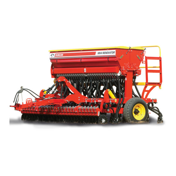
Description of Machine The Duncan ‘Mk4 Renovator’ is a Coil Tine T-boot drill. The box is mounted on a robust frame accommodating large diameter tyres. The ground engaging components are controlled by a hydraulic ram system, giving ample control on ground pressure, good transport clearance and contour following ability. -
Page 7: Dimensions & Capacities
Dimensions & Capacities Pt. No. 67381 Issue 1115... -
Page 8: Safety Symbols On Machine
ATTENTION On the machine important safety information is indicated by these symbols. These highlight general safety aspects in regard to the machine rather than specific hazards. Do not ride or allow passengers on the machine. Under no circumstances are passengers to be permitted on the machine while it is in operation or being transported. -
Page 9: Safety - General
SAFETY - General This section of the manual offers general guidelines for the safe operation of machinery. It does not replace N.B. Throughout this local safety regulations. These guidelines were current at manual important safety the time of publication, but may be superseded by later information is indicated regulations. -
Page 10: Appropriate Dress
SAFETY - General (Continued) Appropriate Dress Wear close fitting clothing and avoid rings or other forms of jewellery which could become caught in the machinery. People with long hair must have it securely fixed and confined close to the head. Refer to local safety standards for protective clothing and recommended safety equipment. -
Page 11: Handle Agricultural Chemicals Safely
SAFETY - General (Continued) Handle Agricultural Chemicals Safely All farm chemicals should be stored, used, handled and disposed of safely and in accordance with the supplier’s/ manufacturer’s recommendations. Read the product label before using, noting any warnings or special cautions, including any protective clothing or equipment that may be required, ie. -
Page 12: Practise Safe Maintenance
SAFETY - General (Continued) Practice Safe Maintenance Keep the machine in safe working condition. Routine maintenance and regular servicing will help reduce risks and prolong the life of the machine. General Maintenance Accidents occur most frequently during servicing and repair. The following general rules must be followed when maintaining or working with machinery: •... -
Page 13: Safety - Machine Specific
SAFETY - Machine Specific This section of the manual gives specific guidelines for the safe operation of the Renovator. These guidelines were current at the time of publication, but may be superseded by later circumstances. They do not necessarily cover every possible hazard and must be read in conjunction with the SAFETY - General section (Page 7 to 10). - Page 14 SAFETY - Machine Specific (Continued) Hazard Points on the Renovator (Continued) Pedestal Chain Guards To prevent hands, etc. getting caught in drive chains, guards are provided to cover sprockets, chain and chain tensioners mounted about the drive pedestal (RHS). These guards must be fitted while using the machine.
-
Page 15: Safety Decals & Safety Guards
SAFETY - Machine Specific (Continued) On end of footboard Item Decal/Guard Pt. No. Qty ‘No Ride’ 43900 ‘Pinch Point/Moving Parts’ 43901 ‘Slippery When Wet’ 43902 ‘Keep Clear’ 43904 Arrows (Inside Box Lid) 43905 Pedestal Drive Guard (Dual box machine) 25995 Pedestal Drive Guard (Single box machine) 25996 Jockey Drive Swing Guard... -
Page 16: Transport
Transport Fig 1 Raise the drill into the transport position and hold at the full extent of the rams for a few seconds to allow cylinders to rephase/equalise. Important - To avoid machine damage due to drill lowering during transport, always close the hydraulic valve on the drawbar. -
Page 17: Operation
Operation General Operation Guidelines Use a sufficiently powerful tractor which is heavy enough to tow the drill safely. Operate the drill at a speed of 6-12 km/hr (4-8 mph). In stony and uneven ground conditions a lower speed is more appropriate Check that the drill is level during calibration and while seeding. - Page 18 Level Drill Use the drawbar turnbuckle or ram to tilt the drill so it is sitting level. An adjustment may be required after a short period of use because the paint wears off the discs and the discs sharpen which in turn improves the penetration abilities.
-
Page 21: Sowing Chart
MK 4 Renovator Seed Drill Sowing Chart Table 3 High & Low Ratio - Wide Row Spacing 180 16 Run 3m and 20 Run 3.5m Seed Rate (kg/ha) Agitator Shaft Gearbox Setting Position PRODUCT Connected Hi/Low Position Type 105 125 148 170 192 Connected Wheat Full... - Page 22 MK4 Renovator Seed Drill Sowing Chart Table 4 High & Low Ratio - Standard Row Spacing 147.5 21 Run 3m and 24 Run 3.5m 147.5 Seed Rate (kg/ha) Agitator Shaft Gearbox Setting Position PRODUCT Connected Hi/Low Position Type 102 128 152 180 208 234...
- Page 23 MK 4 Renovator Seed Drill Sowing Chart Table 5 High & Low Ratio - Narrow Row Spacing 125 24 Run 3m and 28 Run 3.5m Seed Rate (kg/ha) Agitator Shaft Gearbox Setting Position PRODUCT Connected Hi/Low Position Type 121 152 180 213 246 277 Connected Wheat Full...
-
Page 24: Basic Calibration Procedure
Basic Calibration Procedure Gearbox Setting Lever To set the seed rate at the gearbox, slacken the tri knob (1) by turning counter-clockwise and push from below into the position indicated in the Sowing Chart. Retighten the star knob firmly (Fig 6). Important The settings shown in the Sowing Charts (kg/ha) can only serve as reference values. -
Page 25: Seed Calibration
Basic Calibration Procedure (Continued) Seed Calibration The calibration test should be done to confirm the required seed rate and is done with the drill stationary and level. Seed Calibration Procedures Remove the calibration tray from the storage brackets on the seedbox. Place the calibration tray (1) on the support members below the seeders (Fig 10). -
Page 26: Hand Crank Turns For Seed Rate Calibration
Basic Calibration Procedure (Continued) Hand Crank Turns for Seed Rate Calibration The tables represented below are for arable conditions (worked ground) and are calculated to indicate an average situation. If there is any doubt as to the accuracy of these figures for the conditions, it is advisable to run checks on the calibration figures listed. -
Page 27: Use Of Seed Rate Calculator
Basic Calibration Procedure (Continued) Use of Seed Rate Calculator Determining the gear box scale setting using the calculator. Usually the first calibration test yields a different seed rate. However with the value determined from the first test it is possible to determine the correct gearbox setting with the aid of the enclosed disc calculator (Fig 13). -
Page 28: Calibration Deviations
Basic Calibration Procedure (Continued) Calibration Deviations Deviations Between the Calibration Test and the Actual Seed Rate The most frequent cause for changes between the calibration test and the seed rate lies in the flowing properties of seed during sowing. These changes in properties generally result from reactions of the dressing agents to temperature, humidity or abrasion. -
Page 29: Sowing Of Fine Seeds
Hints for Sowing with Variable Speed Fig 14 Gearbox The gearbox allows for stepless changes in the speed of the metering shaft and thus the seed rates. Due to the variations in seed type and application rates there are two speed ranges available. -
Page 30: Sowing Small Seeds
Sowing Peas Peas having the size and shape as illustrated in Fig 19A (e.g. White Field Peas), can be sown in all Duncan Drills with this type of metering wheel. The flap should be set to a gap of at least “3” on the flap setting lever (Page 22, Fig 9). -
Page 31: Hectaremeter Settings
Refer to the operation instructions supplied with your hectaremeter kit for information and operation thereof. (Fig 21). Computronics 1100 Area Meter Setup for Mk4 Renovator The H1 value is the distance the machine travels in mm per pulse detected on the pedestal drive shaft. -
Page 33: Calibration Notes
Renovator Calibration Notes Pt. No. 67381 Issue 1115... -
Page 34: Maintenance & Care
Maintenance & Care General Safety and Accident Prevention Advice Make sure that if the tractor remains attached to the drill that the ignition key is removed. During maintenance the drill should be supported in such a manner that if hydraulic failure was to occur the machine would still be adequately supported. -
Page 35: Lubrication Instructions
Greases should not be mixed as the structure may be weakened by the mixes of different types of thickener, which may cause softening and loss of grease from the bearings by running out. Your Duncan Renovator Seed Drill will give long and efficient... -
Page 36: Maintenance Schedule
Maintenance & Care - Lubrication Instructions Table 10 Daily Weekly Pre Season Components (or after 20Ha) (or after 75Ha) (or 500 Ha) Disc Openers ● ● ● Depth Adjustment Collar ● ● ● Seeders/Agitators/Bottom Flaps ● ● ● Wheel Nuts ●... - Page 37 3 Drive Chains All drive chains (1) (Fig 25) should first be checked after every 20 hours of operation and thereafter weekly or after 75Ha of operation as follows:- The metering wheels of the seed drill are driven via roller chains from the drive wheel. Cleaning of the roller chains is recommended after long periods of operation.
-
Page 38: Storage
Maintenance & Care (Continued) 10 Bottom Flaps (Fig 28) The required seed rate is controlled by both the metering wheels and the bottom flaps. The seed flows from the seed box into the metering wheel housings. Inside the metering wheel housing (1) the seed is caught between the metering wheel (2) and the bottom flap (3). -
Page 39: Troubleshooting/Maintenance Notes
Renovator Troubleshooting Problem Possible Cause Action Refer to Page… Jockey wheel under inflated Check pressure Are the hectare meter settings correct? Check settings Has the calibration procedure been 22-24 Re-calibrate followed correctly? Is the shutter slide open too wide? 22-24 Over Sowing Is the flap setting open too wide? 22-24... - Page 40 Commisioning Phasing Cylinders 1. General (a) The cylinders will re-phase in both directions. Each piston is fitted with 2 poppet valves which open at the end of the stroke to allow oil to bypass the piston. The bypass of oil at the end of the stroke allows for initial bleeding of the system and re-phasing in operation.
- Page 41 Commisioning Phasing Cylinders (continued) 3. Fault Finding (continued) 2. Cylinders moving at different rates (a) Check that there is no air in the system. Raise and lower the machine; all cylinders should move at the same time, any lag indicates that there is air in the system. Re-bleed the system if necessary. (b) Ensure that the cylinders have been connected correctly.
-
Page 45: Calibration Chart And Handy Hints
Calibration Chart and Handy Hints (21R 3m & 24R 3.5m) Pt. No. 67381 Issue 1115... - Page 46 Renovator Maintenance Notes...
-
Page 47: Issue
Pt. No. 67381 Issue 1115...
Need help?
Do you have a question about the MK4 Renovator and is the answer not in the manual?
Questions and answers