Table of Contents
Advertisement
Quick Links
User, Service and Installation Manual
41, 61, 81 Series
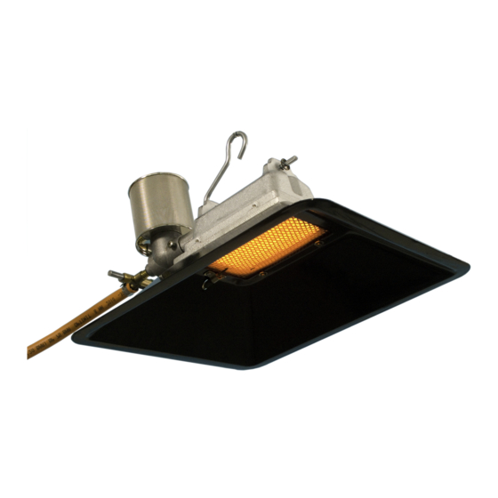
Atmospheric ceramic luminous infra-red heaters for use in well ventilated areas
Country of destination:
GB, IE, MT
General international manual
Alke BV
Industrielaan 11a
3925 BD Scherpenzeel
The Netherlands
Tel: +31 33-277 3824
Fax: +31 33-277 3080
info@alke.nl
www.alke.nl
Advertisement
Table of Contents

Related Manuals for Alke 41 Series


Summary of Contents for Alke 41 Series
- Page 1 41, 61, 81 Series Atmospheric ceramic luminous infra-red heaters for use in well ventilated areas Country of destination: GB, IE, MT General international manual Alke BV Industrielaan 11a 3925 BD Scherpenzeel The Netherlands Tel: +31 33-277 3824 Fax: +31 33-277 3080 info@alke.nl...
-
Page 2: General Information
Warnings • Read this manual carefully before installation and use and keep it for future reference. Make sure that all daily users know the content of this manual. • Install these heaters only in according with this manual and all applicable local and/or national regulations for installation and ventilation of gas heaters. -
Page 3: Installation
Note that the heaters will be a bit discoloured by temperature due to a 5 minutes quality check after manufacturing. The thermostat knob is always delivered separated from the thermostat valve. 1) Remove the protection cover from the thermostat valve. 2) Turn the knob on maximum temperature and push the knob on the valve. - Page 4 Safety Distances to the ceiling (A) >50 cm >60 cm >60 cm to the ground. (B) >60 cm >90 cm >90 cm in front of heater (C) >50 cm >50 cm >50 cm to the back (D) >50 cm >50 cm >50 cm to side walls (E) >50 cm...
- Page 5 the gas type and gas pressure complies with the technical table and data plate information. Remove the black dust cap from the safety device. The gas hose shall be hanging free and have a distance of minimal 1 meter from the ground. This to make sure that animals will not damage the hose.
- Page 6 Gas hose In most installations, the heaters are not connected directly to the gas system but a gas hose is used. Keep the hoses always as short as possible, especially for natural gas and low-pressure LPG. For high pressure LPG, the maximum length (concerning capacity issues) is 5 meter. The gas hoses must be inspected frequently and must be changed within the prescribed intervals.
-
Page 7: Operation
Operation New heaters New heaters need a cleaning period before they are ready for operation. Turn the ventilation to maximum position or place the heaters outside in the open air. Fire the heaters for at least two hours on full capacity to burn-off oily and greasy remnants of the production. -
Page 8: Service And Maintenance
Service and maintenance General The frequency of maintenance is strongly depending on the quality of the combustion air and the intensity of use. When used in poultry houses, maintenance is advised every 6 weeks or by changing the animals. By use in clean environment conditions, the maintenance period can be extended but not longer than 6 months. - Page 9 Internal cleaning The internal part of a heater can be cleaned with compressed air and with a tube brush. If needed do this every day. First clean the outside of the burner. Then the inside of the venturi and burner tube via the dust filter connection.
-
Page 10: Fault Finding Table
Gas pressure too low Declaration of conformity We, Alke B.V., located in Scherpenzeel, The Netherlands, hereby declare that the 41, 61 and 81 series, marked on their data plates with CE and with CE approval/production supervision by Kiwa (number 0063) are in compliance with the following EU legislation:... -
Page 11: Parts List
Parts list Note that the picture shows a model 61 / 81. The picture also can be used to determine the parts of the 101 and 41, although the parts deviate a little bit in shape. Part # Description Part # Description 01640010 Burner house 81-15mm venturi... - Page 12 ** Input Input T **(1x) Holder (mbar) (mbar) (kW Hs) (kW Hs) (g/h or m3/h) (mm) (mm) (mm) 41 series 0,22 m3/h 1,05 I2EK (K) G25.3 25 2,05 0,22 m3/h 1,05 I2H, I2E, I2E+ 0,17 m3/h 0,95 I2ELL (LL) 1,35...
Need help?
Do you have a question about the 41 Series and is the answer not in the manual?
Questions and answers