Advertisement
User, Service and Installation Manual
Global-5, Global-10
Series
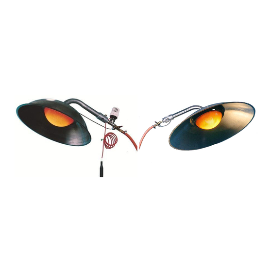
Atmospheric stainless-steel gas infrared heaters for use in well ventilated areas
Country of destination:
GB, IE, MT
General international manual
Global-5
Global-10
Global-5-(T)(2F)(2FT)(S)(2FS)
Global-10-(T)(2F)(2FT)(S)(2FS)
Global-5-(Ei)(2FEi)(SEi)(2FSEi)
Global-10-(Ei)(2FEi)(SEi)(2FSEi)
Alke BV
Industrielaan 11a
3925 BD Scherpenzeel
The Netherlands
Tel: +31 33-277 3824
Fax: +31 33-277 3080
info@alke.nl
www.alke.nl
Version: September 2017
1
manual number: 0009 0440EN
Advertisement
Table of Contents

Related Manuals for Alke Global-5 Series


Summary of Contents for Alke Global-5 Series
- Page 1 Country of destination: GB, IE, MT General international manual Global-5 Global-10 Global-5-(T)(2F)(2FT)(S)(2FS) Global-10-(T)(2F)(2FT)(S)(2FS) Global-5-(Ei)(2FEi)(SEi)(2FSEi) Global-10-(Ei)(2FEi)(SEi)(2FSEi) Alke BV Industrielaan 11a 3925 BD Scherpenzeel The Netherlands Tel: +31 33-277 3824 Fax: +31 33-277 3080 info@alke.nl www.alke.nl Version: September 2017 manual number: 0009 0440EN...
-
Page 2: General Information
Warnings • Read this manual carefully before installation and use and keep it for future reference. Make sure that all daily users know the content of this manual. • Install these heaters only in according with all applicable local and/or national regulations for installation and ventilation of gas heaters. -
Page 3: Installation
equipped with an independent manual thermostat with remote sensor (Ti = integrated sensor) equipped with an individual solenoid valve equipped with an electronic ignition device (EID2G) adjusted for high altitude installation (>1400 meter) Packaging Normally (depending model and order quantity) the heaters are packed per 1, 2 or 4 in a box. Always check the heaters for transport damage directly after receiving them. - Page 4 Place of installation The heaters are intended for use in well ventilated areas only. Do not install the heaters in situations that are not well ventilated. See also below for more ventilation information. Check also your local regulations for the ventilation and room size requirements. The number of heaters per building is depending the type of building, the animals, the insulation, the climate and local wind conditions.
- Page 5 ventilation in the country of installation, we advise to keep a minimum ventilation of 20m3/h per kW heat input. Check regularly if fans are working properly and ventilation openings are not closed. Installation The heaters are intended for suspension only. Use only a chain and S-hooks that are galvanised or made of stainless steel.
- Page 6 S (Ceme) S (Asco) Electrical supply: 230VAC 230VAC 50/60Hz, IP65 230VAC 50Hz, IP65 50/60Hz, IP65 24 VAC 50/60Hz, IP65 24VAC 50Hz, IP65 Power: Max 30VA 17VA 6,3W Current rating: Max 0,2A 0,1A/0,9A 0,05A/0,3A Waiting time T(w) 7 seconds Safety time T(s) 30 seconds Schematic diagram electronic ignition device Timing diagram electronic ignition device...
- Page 7 Gas cylinder supply The gas can also be supplied from LPG gas cylinders. The minimum size is a 11-kg cylinder or larger. Before buying a cylinder make sure that the connections of the gas regulator and the gas valve of the cylinder are of the same type.
-
Page 8: Operation
The gas hose shall always be connected to the heater with the help of hose clips. Not using hose clips at both ends of the gas hose is very dangerous. Make sure that the gas hose never is heated above 40 degrees Celsius. - Page 9 Manual operated heaters Global-(5, 10), -T, -2F, -2FT, -S, -2FS and -2FDi versions: 1) Open all gas taps and turn the thermostat (T) or gas pressure regulator on maximum pressure, open the solenoid valve (S) by electricity. 2) Keep a flame of a BBQ lighter (or long match) in the ignition hole of the burner globe.
-
Page 10: Service And Maintenance
Visual examination of the flame Check after every ignition (and also during regular barn inspection) if a heater still burns correctly. The flame shall remain always inside the outer burner globe. The burner globe shall be equal red/orange in high firing position and having a blue flame. Some types will have in high fire position a dark ring on the globe. - Page 11 WARNING: always switch off the heater and isolate the gas and electricity before carrying out any service or maintenance operation. Order of maintenance • First clean the heater and filters as described below by daily maintenance. Take the venturi (22) out during cleaning to remove dust directly behind it.
- Page 12 Advice: Lots of farmers use a second set of dust filters. They replace the dusty ones directly with the clean ones and clean the filters outside the barn to avoid unneeded disturbance of the animals. Internal cleaning The internal part of a heater can be cleaned with compressed air and with a tube brush. If needed do this every day.
-
Page 13: Fault Finding Table
Consult the technical table for the proper ring (38) distance. (Rings are counted from the gas safety device). Check the gas supply for the proper gas pressure and gas type and do a leakage test first. Take the heater into operation and do a visual examination of the flame as explained above. End-of life disposal The infrared heaters are made up of valuable recyclable materials. - Page 14 Injector partly blocked Declaration of conformity We, Alke B.V., located in Scherpenzeel, The Netherlands, hereby declare that the Global series, marked on their dataplates with CE and with CE approval/production supervision by Kiwa (number 0063) are in compliance with the following EU legislation:...
-
Page 15: Parts List
Parts list The parts list below is a combination list of both Global 5 and 10 models. Most parts of both models are identical. Parts that differ are specified with the Global model identification. Consult the data plate to determine the model you have before using this list. 12005000 Burner replacement kit Global 5 (set of parts: 3, 5, 6, 7, 8, 10, 11, 12, 14, 15, 18) 12006000... - Page 16 Art / Drawing Nr Description Amount 02354000 Reflector Global 5 02355000 Reflector Global 10 02525000 Burner Globe Global 5 02527000 Burner Globe Global 10 07734000 Hexagonal bolt M5x30 02224000 Mounting Ring SS 02524000 Burner Globe Small 02222000 Bottom Plate Global 5 02225000 Bottom Plate Global 10 08892000...
- Page 17 ** (1x) Holder Ti, S ** (-)* (mbar) (mbar) (kW Hs) (kW Hs) (g/h or m3/h) (mm) (mm) (mm) Global-5 series I2H, I2E G20 300 0,87 0,50 m3/h 0,77 I2H, I2E G20 300 0,63 0,46 m3/h 0,60/0,59 0,31 (Di)
Need help?
Do you have a question about the Global-5 Series and is the answer not in the manual?
Questions and answers