Table of Contents

Related Manuals for Glensound GS-SW012


Summary of Contents for Glensound GS-SW012
- Page 1 GS-SW012 2 Input Reference Microphone Amplifier for Comparison of Microphones PRODUCT DETAILS 6 BROOKS PLACE, MAIDSTONE, KENT, ME14 1HE. ENGLAND. TEL: +44 (0) 1622 753662 Visit our Website at www.glensound.com FAX: +44 (0) 1622 762330...
- Page 2 Glensound Electronics Ltd Thank you for choosing a new Glensound product. All rights reserved. Information contained in this manual is subject to change without notice, if in doubt please contact us for the latest product information. If you need any help with the product then we can be contacted at: Glensound Electronics Ltd 1 –...
-
Page 3: Product Warranty
PRODUCT WARRANTY: All equipment is fully tested before dispatch and carefully designed to provide you with trouble free use for many years. We have a policy of supporting products for as long as possible and guarantee to be able to support your product for a minimum of 10 years. For a period of one year after the goods have been despatched the Company will guarantee the goods against any defect developing after proper use providing such defects arise solely from faulty materials or workmanship and... - Page 4 2 Input Reference Microphone Amplifier This declaration of conformity is issued under the sole responsibility of the manufacturer. This equipment is manufactured by Glensound Electronics Ltd of Brooks Place Maidstone Kent ME14 1HE is marked and conforms to the following Union harmonisation legislation:...
- Page 5 RoHS DIRECTIVE RoHS 2 Directive 2011/65/EU restricts the use of the hazardous substances listed below in electrical and electronic equipment. This product conforms to the above directive and for these purposes, the maximum concentration values of the restricted substances by weight in homogenous materials are: Lead 0.1%...
- Page 6 WASTE ELECTRICAL AND ELECTRONIC EQUIPMENT REGULATIONS 2006 (WEEE) Glensound Electronics Ltd is registered for business to business sales of WEEE in the UK our registration number is: WEE/JJ0074UR Page 6 of 15...
-
Page 7: Table Of Contents
Issue 1 Description Page No. Contents PRODUCT WARRANTY: ................................3 OVERVIEW ......................................8 GS-SW012 PANEL LAYOUT................................. 9 Front Panel ....................................9 Front Panel Features................................9 Side Panel ....................................12 Rear Panel Features ................................12 AUDIO BLOCK DIAGRAM ................................13 SPECIFICATIONS ..................................14 WIRING INFORMATION ................................ -
Page 8: Overview
OVERVIEW GS-SW012 features two low noise reference microphones amplifiers designed for testing and comparing microphones. There are two headphone monitoring amplifiers enabling two users to listen to the microphone inputs. A front panel switch selects which of the two inputs is being sent to the outputs. -
Page 9: Gs-Sw012 Panel Layout
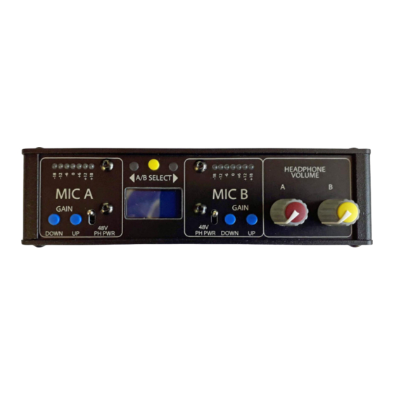
GS-SW012 PANEL LAYOUT Front Panel HEADPHONE SELECTED LEDs MIC B PPM MIC B GAIN MIC A PPM VOLUMES SWITCHES MIC A GAIN MIC B PH SWITCHES LCD DISPLAY MIC A PH INPUT SELECT SWITCH Front Panel Features 1. MIC A PPM These 7 LEDs provide a visual indication of the A microphone input’s output... - Page 10 4. MIC B GAIN SWITCHES Pressing these switches adjust the B microphone’s input gain up or down in 1dB steps. The current actual gain being applied to the B microphone input will be displayed on the LCD display. Once the minimum gain of 10dB is reached the unit automatically silently switches in a 14dB hardware pad on the input and changes the mic amps gain to compensate.
- Page 11 9. LCD Display The small backlit liquid crystal display (LCD) is used to show the gains of the two microphone inputs. After a period of inactivity the back light dims but will automatically resume full brightness when any of the gain switches are pressed. The gain levels are shown in dB and refer the amount of gain being applied to the microphone input.
-
Page 12: Side Panel
Side Panel HEADPHONE ANALOGUE MICROPHONE DC INPUT OUTPUT OUTPUTS INPUTS Rear Panel Features 11. DC INPUT This is a 2.5mm barrel connector with centre +Ve. It can accept input voltages between 9 and 15V DC and the external power supply should provide at least x Watts. -
Page 13: Audio Block Diagram
AUDIO BLOCK DIAGRAM Page 13 of 15... -
Page 14: Specifications
SPECIFICATIONS LINE OUTPUTS MIC INPUTS Frequency Response Maximum Output Level -0.2dB 50Hz to 20kHz +18dB Input Gain Range Output Impedance +65 to -4dB <50 Ohm Note: 14dB Pad inserted when gain reaches +10 Interchannel Crosstalk >101dB @ 0dB with1kHz tone Input Gain Resolution Output Type 1dB steps... -
Page 15: Wiring Information
WIRING INFORMATION Standard XLR Pin Outs STANDARD XLR AUDIO PINOUTS: 1: Ground/ Earth 2: INPHASE/ POSITIVE/ MIC + 3: MATE/ NEGATIVE/ MIC - XLR PLUG (MALE) XLR SOCKET (FEMALE) Standard Headphone Wiring STANDARD HEADPHONE WIRING: RING TIP: A/ LEFT Ear RING: B/ RIGHT Ear SLEEVE SLEEVE: Common/ Earth...
Need help?
Do you have a question about the GS-SW012 and is the answer not in the manual?
Questions and answers