Table of Contents
Advertisement
Advertisement
Chapters
Table of Contents

Related Manuals for ABB ACS1000i air-cooled


Summary of Contents for ABB ACS1000i air-cooled
- Page 1 — M ED I UM V O LTA G E A C DR I V E S ACS1000i air-cooled User manual...
- Page 2 — ACS1000i air-cooled The flexibility you require. The reliability you expect. Document name ACS1000i air-cooled user manual Document owner ABB Switzerland Ltd. Medium voltage AC drives Document number 3BHS206977 E01 Rev H Number of pages Release date 2020-03-18 — new.abb.com/drives/medium-voltage-ac-drives...
- Page 3 Contents — ACS1000i air-cooled User manual...
- Page 4 About this manual Important safety information Power electronics and cabinet features Control system Transportation, storage and disposal Mechanical installation Electrical installation Commissioning Operation CDP control panel Preventive and corrective maintenance...
- Page 5 — About this manual — 5 - 16...
-
Page 6: Table Of Contents
Copyright notice Equipment covered by this manual Structure of the user documentation Terms and abbreviations Trademarks Related documentation Target groups and required qualification 1.7.1 Handling 1.7.2 Mechanical installation 1.7.3 Electrical installation 1.7.4 Operation 1.7.5 Maintenance User’s responsibilities Intended use of equipment 1.10 Cyber security disclaimer 1.11... -
Page 7: Copyright Notice
(eg, layout drawings, wiring diagrams, technical data, engineering notes). If information is required beyond the instructions in this manual, refer the matter to ABB. Structure of the user documentation The complete set of user documentation of a standard drive consists of this manual and... -
Page 8: Terms And Abbreviations
Terms and abbreviations The following table lists terms and abbreviations you should be familiar with when using this user manual. Some of the terms and abbreviations used in this user manual are unique to ABB and might differ from the normal usage. -
Page 9: Trademarks
Resistance temperature detector or device The RTD is a temperature sensor where the change in electrical resistance is used to measure the temperature. Safeline ABB synonym for uninterruptable power supply Supervisory signal Indicates the operating condition of a circuit or device. Software... -
Page 10: Target Groups And Required Qualification
/ or burn. For this reason, only personnel who have a thorough knowledge of the drive and the industrial environment and have obtained the required qualification should handle, install, operate, or maintain the drive. 3BHS206977 E01 REV H ACS1000I AIR-COOLED USER MANUAL 10/174... -
Page 11: Handling
It is the responsibility of those in charge of the drive to ensure that each person involved in the installation, operation or maintenance of the drive has received the appropriate training and has thoroughly read and clearly understood the instructions in this manual and the relevant safety instructions. 3BHS206977 E01 REV H ACS1000I AIR-COOLED USER MANUAL 11/174... -
Page 12: Intended Use Of Equipment
ABB and its affiliates are not liable for damages and/or losses related to such security breaches, any unauthorized access, interference, intrusion, leakage and/or theft of data or information. -
Page 13: Quality Certificates And Applicable Standards
Quality certificates and applicable standards The following certificates and conformity declarations are available with ABB: ISO 9001 and ISO 14001 certificates stating that ABB Switzerland Ltd has implemented and maintains a management system which fulfills the requirements of the normative standards... -
Page 14: Items Covered By Delivery
(4) Input disconnector lever: only supplied if drive is equipped with an integrated input disconnector Note: For a complete list of the items in the delivery, see the shipping note. 3BHS206977 E01 REV H ACS1000I AIR-COOLED USER MANUAL 14/174... -
Page 15: Identifying The Delivery
The drive and accessories are identified by the type code printed on the rating label. The label provides information on the type of drive, the rated voltage, the frequency and the current of the main and the auxiliary power supply. 3BHS206977 E01 REV H ACS1000I AIR-COOLED USER MANUAL 15/174... - Page 17 — Important safety information — 17 - 28...
- Page 18 Overview 2.1.1 Safety standards Safety messages Damage prevention information Product safety labels General safety instructions The 7 steps that save lives Possible residual risks Important note - main circuit breaker 2.8.1 Safety and protection requirements 2.8.2 Minimum requirements for MCB and MCB control 2.8.3 Maintenance recommendation...
-
Page 19: Overview
CAUTION! Indicates a hazardous situation which, if not avoided, could result in minor or moderate injury. Damage prevention information NOTICE NOTICE: is used to address practices not related to physical injury, but which can result in equipment damage. 3BHS206977 E01 REV H ACS1000I AIR-COOLED USER MANUAL 19/174... -
Page 20: Product Safety Labels
The sign alerts personnel to the high voltage which can be present on the secondary side of the input transformer until the main circuit breaker has been opened and secured and the drive has been de-energized and grounded. 3BHS206977 E01 REV H ACS1000I AIR-COOLED USER MANUAL 20/174... -
Page 21: General Safety Instructions
Inform the involved personnel about the potential safety hazards In case of fire in the drive room: Observe the established rules and regulations for fire safety Only allow firefighters with the appropriate PPE to enter the drive room 3BHS206977 E01 REV H ACS1000I AIR-COOLED USER MANUAL 21/174... -
Page 22: The 7 Steps That Save Lives
02 IMPORTANT SAFETY INFORMATION The 7 steps that save lives ABB’s 7 steps that save lives concept is a series of actions that must take place prior to commencing work on or near electrical installations. Everyone in the working party must be... - Page 23 Ensure the work can proceed without danger Complete and verify the “Permit to Work” For an example “Permit to Work”, see “Permission for working and permit to work for test work at test stations” (3BHS817511 E30) 3BHS206977 E01 REV H ACS1000I AIR-COOLED USER MANUAL 23/174...
-
Page 24: Possible Residual Risks
Operation of the equipment outside the scope of the specifications External influence on or damage of the equipment Wrong parameter settings Software errors Faulty hardware Hazardous substances can be emitted from drive system components caused by: Incorrect disposal of components 3BHS206977 E01 REV H ACS1000I AIR-COOLED USER MANUAL 24/174... -
Page 25: Important Note - Main Circuit Breaker
SF6 circuit breakers Fused contactors or motor control centers Note: The MCB is not included in the drive supply. A dedicated protection relay is used for: Transformer protection Backing up the drive protection 3BHS206977 E01 REV H ACS1000I AIR-COOLED USER MANUAL 25/174... -
Page 26: Safety And Protection Requirements
For safety and protection reasons, the MCB must meet the stipulated minimum requirements of the specifications of ABB MV Drives. It is the system integrator's responsibility to ensure that the minimum requirements are met. The minimum requirements for the MCB are stated in this note and in the respective MCB specifications, which are available for each medium voltage drive from ABB. -
Page 27: Maintenance Recommendation
(5) Maximum protection trip time (6) Maximum safety trip time In order to meet the stipulated safety requirements, ABB recommends one of the following: MCB is equipped with 2 independent opening coils MCB is equipped with an opening coil and an undervoltage coil for monitoring of the control voltage Upstream protection coordination scheme is provided which uses the "breaker failure"... - Page 29 — Power electronics and cabinet features — 29 - 56...
- Page 30 Overview Main components of the drive system Power supply configurations 3.3.1 Main power supply configurations 3.3.2 Auxiliary power supply configurations Drive topology 3.4.1 Overview 3.4.2 Terminal compartment 3.4.3 Control compartment and terminal compartment 3.4.4 Transformer and rectifier compartment 3.4.5 Rectifier 3.4.6 Grounding switch 3.4.7...
- Page 31 Cabinet design 3.5.1 Mechanical design 3.5.2 Additional cabinets Door locking system 3.6.1 Additional cabinets Arc resistant design (optional) 3.7.1 Internal arc classification 3.7.2 Power compartment doors 3.7.3 Associated protection requirement Space heaters...
-
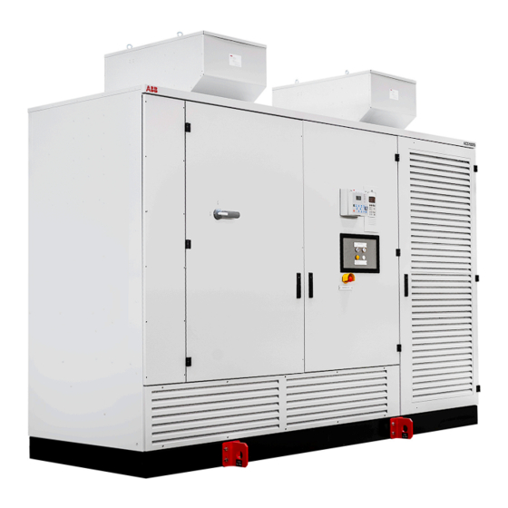
Page 32: Overview
Drive topology and main features Available main and auxiliary power configurations Power electronic components of the drive Cooling system Cabinet features such as the grounding switch and the electro-mechanical door interlock Figure 3-1: ACS1000i air-cooled 3BHS206977 E01 REV H ACS1000I AIR-COOLED USER MANUAL 32/174... -
Page 33: Main Components Of The Drive System
The protection for the transformer is always included. Drive: For more information, see “3.4 Drive topology” on page 36. Motor: For more information, see the induction motor specification. 3BHS206977 E01 REV H ACS1000I AIR-COOLED USER MANUAL 33/174... -
Page 34: Power Supply Configurations
(10)Power electronic components (3) Control and cooling system (11) Diode rectifier (4) Auxiliary power distribution (12)DC link (5) Cooling system (13)Inverter (6) Control system (14)Motor (7) Main power supply (8) Switchgear 3BHS206977 E01 REV H ACS1000I AIR-COOLED USER MANUAL 34/174... -
Page 35: Main Power Supply Configurations
For more information on the auxiliary power interface of the drive, see “Appendix D – Wiring diagrams”. For information on the rated voltage(s) and current(s), see the rating plate of the drive. 3BHS206977 E01 REV H ACS1000I AIR-COOLED USER MANUAL 35/174... -
Page 36: Drive Topology
3.4.1 Overview 3.4.1.1 Drive with combined input disconnector and grounding switch Figure 3-4: ACS1000i air-cooled with combined input disconnector and grounding switch (1) Terminal compartment with combined input (3) Control compartment disconnector and grounding switch, terminals for (4) DC-link and inverter compartment... - Page 37 03 POWER ELECTRONICS AND CABINET FEATURES 3.4.1.2 Drive with grounding switch Figure 3-5: ACS1000i air-cooled with grounding switch (1) Terminal compartment with terminals for feeder (3) Control compartment and motor cables (4) DC-link and inverter compartment (2) Transformer and rectifier compartment...
-
Page 38: Terminal Compartment
(B) (1) Input disconnector with feeder cable terminals (3) Motor cable terminals (2) Feeder cable terminals For more information on cable entry and connection, see “07 Electrical installation” on page 89. 3BHS206977 E01 REV H ACS1000I AIR-COOLED USER MANUAL 38/174... -
Page 39: Control Compartment And Terminal Compartment
89. Figure 3-7: Control compartment with open door (1) Internal view of control compartment (3) Control and auxiliary cable entry area (2) Local operator control panel (back side) 3BHS206977 E01 REV H ACS1000I AIR-COOLED USER MANUAL 39/174... -
Page 40: Transformer And Rectifier Compartment
3.4.5 Rectifier The 24-pulse diode rectifier converts the AC voltage of the main power supply and connects its output to the minus, neutral point, and plus side of the DC link. 3BHS206977 E01 REV H ACS1000I AIR-COOLED USER MANUAL 40/174... -
Page 41: Grounding Switch
The switch is electro-mechanically interlocked with a discharge monitoring circuit that prevents turning of the switch while the DC-link capacitors are still charged. When the drive is grounded, the DC link of the drive is connected to the PE ground busbar. 3BHS206977 E01 REV H ACS1000I AIR-COOLED USER MANUAL 41/174... - Page 42 Input disconnector is open and grounding (3) Grounding switch in grounded position switch is closed (grounded). (4) Combined input disconnector and grounding switch position I: Input disconnector is closed and grounding switch is open (not grounded). 3BHS206977 E01 REV H ACS1000I AIR-COOLED USER MANUAL 42/174...
-
Page 43: Trapped Key Interlock (Option)
The drive features a fuseless protection design. The IGCTs are placed between the rectifier and the DC link. If a severe fault occurs, the IGCTs directly isolate the inverter from the main power supply. 3BHS206977 E01 REV H ACS1000I AIR-COOLED USER MANUAL 43/174... -
Page 44: Inverter
Therefore, standard motors can be used, and voltage reflections in the motor cables are eliminated. Output voltage: 4.16 kV Output frequency: 60 Hz Figure 3-13: Voltage and current waveforms at drive output 3BHS206977 E01 REV H ACS1000I AIR-COOLED USER MANUAL 44/174... -
Page 45: Cooling System
EC fans: The electronically commutated (EC) fans are controlled via an analog signal from the drive based on the inverter current. The EC fan speed is controlled depending on the required cooling. 3BHS206977 E01 REV H ACS1000I AIR-COOLED USER MANUAL 45/174... - Page 46 (1) Group 1: fan 1 of inverter (3) Group 2: fan 1 of transformer (2) Group 1: fan 2 of inverter (if redundant) (4) Group 2: fan 2 of transformer (if redundant) 3BHS206977 E01 REV H ACS1000I AIR-COOLED USER MANUAL 46/174...
- Page 47 (6) 4 hours: default operating time of fan 2 (group 2) (3) Group 2 (7) On (4) 10 hours: default cycle time during which fan 1 (8) Off and fan 2 run alternately 3BHS206977 E01 REV H ACS1000I AIR-COOLED USER MANUAL 47/174...
- Page 48 (5) Reduced fan speed (3) Drive load (6) Minimum fan speed For more information on parameter settings for operating times, grouping the fans, see “Appendix G – Signal and parameter table”. 3BHS206977 E01 REV H ACS1000I AIR-COOLED USER MANUAL 48/174...
-
Page 49: Optional Braking Chopper
Figure 3-19: ACS1000i with braking chopper (1) The braking chopper is controlled and monitored by the ACS1000. VCs2 Figure 3-20: Principle diagram (1) Rectifier (3) Inverter (2) Braking chopping (4) Braking resistor 3BHS206977 E01 REV H ACS1000I AIR-COOLED USER MANUAL 49/174... - Page 50 ACS1000. Braking is then only possible when the temperature falls below the threshold. 3BHS206977 E01 REV H ACS1000I AIR-COOLED USER MANUAL 50/174...
- Page 51 1.350 ACS 1013-W1 6000 1.500 2500 ACS 1014-W1 7270 1.350 ACS1012-W2 4200 1.680 ACS 1013-W2 6000 2.130 2500 ACS 1014-W2 7270 2.130 ACS 1013-W3 6000 2.500 2500 ACS 1014-W3 7270 2.500 3BHS206977 E01 REV H ACS1000I AIR-COOLED USER MANUAL 51/174...
-
Page 52: Cabinet Design
Motor-operated output disconnector (attached to the left of the drive, 1 in Fig. 3-22) Synchronizing bypass unit (attached to the left of the drive) Braking chopper unit (attached to the right of the drive) 3BHS206977 E01 REV H ACS1000I AIR-COOLED USER MANUAL 52/174... - Page 53 03 POWER ELECTRONICS AND CABINET FEATURES Figure 3-22: ACS1000i with additional cabinet (1) For more information, see: “Appendix A – Additional manuals” “Appendix C – Mechanical drawings” 3BHS206977 E01 REV H ACS1000I AIR-COOLED USER MANUAL 53/174...
-
Page 54: Door Locking System
The door of an additional cabinet which contains medium voltage (eg, braking chopper, output disconnector) is secured by a door monitoring switch. The switch releases the door when the DC link of the drive has discharged and the drive has been grounded. 3BHS206977 E01 REV H ACS1000I AIR-COOLED USER MANUAL 54/174... -
Page 55: Arc Resistant Design (Optional)
The optional “Arc Resistant Design” provides the drive with arc fault protection in accordance with IEC 62477-2. The ABB arc resistant classes in Table 3-2 indicate the type of arc proofing that a drive has. Depending on the drive configuration, classes I, II and III are available for an ACS1000i. -
Page 56: Associated Protection Requirement
Associated protection requirement The arc resistant design requires associated protections that are not included in the scope of the delivery, ie, a main circuit breaker and for ABB Class III protection, external fuses on the drive input side. For more information: MCB overview: “2.8 Important note - main circuit breaker”... - Page 57 — Control system — 57 - 70...
- Page 58 Overview Main components 4.2.1 Local control panel 4.2.2 AMC circuit board I/O interfaces 4.3.1 IOEC I/O modules 4.3.2 Serial communication interface (fieldbus) 4.3.3 Pulse encoder interface NTAC (option)
-
Page 59: Overview
(8) AMC circuit board (2) Higher-level control system (9) Fiber-optics (3) Fieldbus (10)INT circuit board (4) DDCS (11) IOEC1 (5) RS485 (12)IOEC2 (6) CDP control panel (13)IOEC3 (optional) (7) PC tools (14)IOEC4 (optional) 3BHS206977 E01 REV H ACS1000I AIR-COOLED USER MANUAL 59/174... -
Page 60: Main Components
(9) Fused terminal block for internal aux. power For information on the devices present in the control compartment, see “Appendix D – Wiring diagrams”. For information on the transformer protection, see “Appendix A– Additional manuals”. 3BHS206977 E01 REV H ACS1000I AIR-COOLED USER MANUAL 60/174... -
Page 61: Local Control Panel
These internal functions are not programmable by the user. Optionally, the AMC circuit board can monitor signals from external equipment. These can be activated and adjusted with Parameters. 3BHS206977 E01 REV H ACS1000I AIR-COOLED USER MANUAL 61/174... - Page 62 The main circuit breaker (MCB) is an important switching and protection device of the drive system. Therefore it must only be controlled and monitored by the drive. For more information, see: “2.8 Important note - main circuit breaker” on page 25 3BHS206977 E01 REV H ACS1000I AIR-COOLED USER MANUAL 62/174...
- Page 63 Serial communication interface (fieldbus) for serial data transfer to a higher-level control system (see “4.3.2 Serial communication interface (fieldbus)” on page 70) Pulse encoder interface NTAC (option) (see “4.3.3 Pulse encoder interface NTAC (option)” on page 70) 3BHS206977 E01 REV H ACS1000I AIR-COOLED USER MANUAL 63/174...
- Page 64 04 CONTROL SYSTEM PC-based service tools comprising: • DriveWare® software tools: commissioning and maintenance tools, ie, DriveWindow and DriveDebug, and DriveOPC for data transfer between ABB drives and Windows®-based applications. • NETA-21 with ABB Ability monitoring contract (optional): monitoring and diagnostics tool that allows access to the drive from any location in the world via a secure Internet connection.
- Page 65 The operating mode is also recommended when two external control stations exist from where the reference value can be set and the drive can be started and stopped. The external control station is selected via a digital input. 3BHS206977 E01 REV H ACS1000I AIR-COOLED USER MANUAL 65/174...
-
Page 66: I/O Interfaces
0 - 20 mA, 4 - 20 mA, 0 - 10 V, 2 - 10 V Individually scalable by parameter = 105 Ω for current input Input resistance = 250 k Ω for voltage input Common mode voltage Maximum: 48 V Isolation level 350 V (AC) 3BHS206977 E01 REV H ACS1000I AIR-COOLED USER MANUAL 66/174... - Page 67 The output is protected by a PTC-resistor against short- circuit and external applied overvoltages. Table 4-5: 24 V internal voltage supply Output voltage Available output voltage Unregulated 24V 180 mA 3BHS206977 E01 REV H ACS1000I AIR-COOLED USER MANUAL 67/174...
- Page 68 (6) DDCS fiber optics * (2) Digital inputs (7) I/O Emergency OFF function * (3) 24 V internal voltage (8) Power supply (factory-installed wiring) (4) Analog inputs (9) Voltage mode (5) Analog outputs (10)Current mode 3BHS206977 E01 REV H ACS1000I AIR-COOLED USER MANUAL 68/174...
- Page 69 191, and the last digit, 1, means that our part is the first assembly on the page. This identification label number is the key to track electrical devices throughout the drive and in ABB documentation. The designation for each IOEC module is shown in Table 4-6.
-
Page 70: Serial Communication Interface (Fieldbus)
For more information on the device, see "Installation and Start-up Guide for the Pulse Encoder Module NTAC-0x" [16]. +24V 24/15 Figure 4-9: NTAC-02 pulse encoder interface Terminals X1 Terminals X2 Channel A 24 V Channel B 24/25 Channel Z Shield +24 V 3BHS206977 E01 REV H ACS1000I AIR-COOLED USER MANUAL 70/174... - Page 71 — Transportation, storage and disposal — 71 - 78...
- Page 72 Safety Transport conditions Unpacking and inspection Lifting and transportation 5.4.1 General notes on transportation 5.4.2 Using a crane 5.4.3 Using rollers Storage 5.5.1 Storage conditions 5.5.2 Storing the drive 5.5.3 Storage and handling of spare parts Disposal of packaging materials and components...
-
Page 73: Safety
2. Check the drive and accompanying equipment for damages. 3. Compare the complete delivery with the purchase order and the packing list. 4. If parts are missing or damaged, immediately inform the shipping company and the ABB service organization. Note: It is recommended to photograph the damages and send the photographs to ABB. -
Page 74: Using A Crane
Lift the cabinet slowly and steadily to the required clearance height maintaining the cabinet in upright position. Check the horizontal position of the cabinet. Reposition the slings if necessary. 3BHS206977 E01 REV H ACS1000I AIR-COOLED USER MANUAL 74/174... -
Page 75: Using Rollers
1 m. Place at least 4 rollers in the area directly underneath the lifting rings. Figure 5-3: Moving the drive backwards or forwards (1) Minimum 1.0 m (2) Minimum 4 rollers 3BHS206977 E01 REV H ACS1000I AIR-COOLED USER MANUAL 75/174... -
Page 76: Storage
Storage time The drive can be stored for up to one year in the original packaging as long as it is not damaged or opened. For information on longer storage periods, contact the ABB service organization. 5.5.2 Storing the drive If the drive is taken out of service for a longer time proceed as follows: 1. -
Page 77: Storage And Handling Of Spare Parts
(ESD), which can damage these devices. Check the spare parts immediately after receipt for damages. Report any damage to the shipping company and the ABB service organization. Observe the following to maintain spare parts in good condition and to keep the warranty valid... - Page 79 — Mechanical installation — 79 - 88...
- Page 80 Safety Overview of installation work General notes on installation 6.3.1 Dimensions and clearances 6.3.2 Cabinet roof 6.3.3 Fire protection 6.3.4 Cable duct material Preparing the floor Fixing the cabinet to the floor Installing the fans 6.6.1 Additional cabinet compartments...
- Page 81 To prevent fire spreading into the drive, apply suitable fire protection measures. 6.3.4 Cable duct material Use non-flammable material with non-abrasive surface. To prevent dust, humidity and animals entering the cabinet, protect the cable entries. 3BHS206977 E01 REV H ACS1000I AIR-COOLED USER MANUAL 81/174...
- Page 82 Fixing the cabinet to the floor Important: If the doors of medium voltage compartments cannot be opened, contact the ABB service organization. 1. Drill fixing holes into the floor as indicated on the layout drawing. Figure 6-1: Position of mounting holes...
- Page 83 Anchor bolts as illustrated, or screws and nuts of size M16 are recommended. Insert the screws from the ends of the cabinet base or via the holes inside the cabinet. Figure 6-3: Fixing the cabinet to the floor 3BHS206977 E01 REV H ACS1000I AIR-COOLED USER MANUAL 83/174...
- Page 84 Drives without fan redundancy have two fans (Fig. 6-5), either two large fans or one large and one small fan. Figure 6-5: Standard fan installation Drives with redundancy have one of the following fan configurations: 3BHS206977 E01 REV H ACS1000I AIR-COOLED USER MANUAL 84/174...
- Page 85 4. Align the holes in front of the cutout on the drive (Fig. 6-4) with the shock absorbers under the front of the fan unit and align the shock absorbers in the cabinet behind the cutout with the holes underneath the back of the fan unit. 3BHS206977 E01 REV H ACS1000I AIR-COOLED USER MANUAL 85/174...
- Page 86 6. Secure the fan or the plate underneath the small fan that is being installed over one of the large roof cutouts. For the front, use two M8x12 bolts and for inside the cabinet, use two M8 locking washers. 3BHS206977 E01 REV H ACS1000I AIR-COOLED USER MANUAL 86/174...
- Page 87 8. Connect the fan motor cable according to the wiring diagram. 6.6.1 Additional cabinet compartments If optional additional cabinet compartments are delivered as separate units, they must be joined to the drive on site according to the supplied specific mounting instructions. 3BHS206977 E01 REV H ACS1000I AIR-COOLED USER MANUAL 87/174...
- Page 89 — Electrical installation — 89 - 104...
- Page 90 Safety Overview of installation work Cable requirements Ground cable connection and cable shield connections Power cables, ground cables and equipotential bonding conductor 7.5.1 Safety 7.5.2 Determining the cable length 7.5.3 MV cable entry from top 7.5.4 MV cable entry from bottom 7.5.5 Connecting the cables Auxiliary power, control and serial...
-
Page 91: Safety
When the electrical installation is completed, the main and auxiliary power supply to the drive must not be switched on without the consent of the ABB commissioning personnel. Take appropriate measures to prevent main and auxiliary power supply being switched on during installation. - Page 92 07 ELECTRICAL INSTALLATION Figure 7-1: Grounding the drive system (1) Drive with integrated transformer (4) Ground cable (2) Motor (5) Equipotential bonding conductor (3) Earth electrode 3BHS206977 E01 REV H ACS1000I AIR-COOLED USER MANUAL 92/174...
-
Page 93: Power Cables, Ground Cables And Equipotential Bonding Conductor
Determining the cable length 1. Determine the required length of a cable between the point of entry and the connection point inside the cabinet. 2. Cut the cable to the required length before connection. 3BHS206977 E01 REV H ACS1000I AIR-COOLED USER MANUAL 93/174... -
Page 94: Mv Cable Entry From Top
MV cable entry from top Figure 7-2: Top cable entry – installation material (1) Cable entry box (5) 6x M6 (2) Insulating barrier (6) 6x M6 (3) Brackets (7) 2x M6x12 (self-tapping) (4) 6x M6x16 3BHS206977 E01 REV H ACS1000I AIR-COOLED USER MANUAL 94/174... - Page 95 Note: If the input voltage of the drive is higher than 6.9 kV, continue with the following steps, ie, “7.5.3.2 Installing the insulating barrier for top cable entry” on page 96. 3BHS206977 E01 REV H ACS1000I AIR-COOLED USER MANUAL 95/174...
- Page 96 2. Remove the protective film from the insulating barrier. 3. Fasten the insulating barrier at the places indicated. Insulating barrier 2. 2x M6x12 (self-tapping) Figure 7-4: Insulating barrier placement for top cable entry 3BHS206977 E01 REV H ACS1000I AIR-COOLED USER MANUAL 96/174...
-
Page 97: Mv Cable Entry From Bottom
(1 in Fig. 7-6) and (2 in Fig. 7-6). Input voltage of the drive is greater than 6.9 kV: fasten the cable entry box at the places indicated by (1 in Fig. 7-6). 3BHS206977 E01 REV H ACS1000I AIR-COOLED USER MANUAL 97/174... - Page 98 1. Remove the protective film from the insulating barrier. 2. Fasten three brackets to the insulating barrier in the locations indicated in Fig. 7-7. Figure 7-7: Bracket location on insulating barrier (1) 3x M6x12 (self-tapping) 3BHS206977 E01 REV H ACS1000I AIR-COOLED USER MANUAL 98/174...
-
Page 99: Connecting The Cables
Check the insulation of each cable before connection and verify that the results are within the specification of the cable manufacturer. Leave the cable conductors unconnected at both ends until the commissioning engineer has given permission. 3BHS206977 E01 REV H ACS1000I AIR-COOLED USER MANUAL 99/174... - Page 100 Figure 7-9: Power cable terminals in a terminal compartment without an input disconnector (A) and a terminal compartment with an input disconnector (B) (1) Terminals for transformer secondary cables (3) 3 Input disconnectors (2) 2 terminals for motor cables 3BHS206977 E01 REV H ACS1000I AIR-COOLED USER MANUAL 100/174...
- Page 101 ] coating) is used, the connection does not have to be lubricated. 7.5.5.4 Tightening torque Tighten bolted connections with bolts of sizes M10 and greater with the recommended nominal torque for the bolt size used. 3BHS206977 E01 REV H ACS1000I AIR-COOLED USER MANUAL 101/174...
-
Page 102: Auxiliary Power, Control And Serial Communication Cables
2. Cut the cable to the required length before connection. Figure 7-11: Cable entry from top (A), from bottom (B) Note: ABB recommends sealing the bottom cable entry with polyurethane foam. 3BHS206977 E01 REV H ACS1000I AIR-COOLED USER MANUAL... -
Page 103: Preparing Cables For Cable Entries With Cable Glands
Figure 7-13: Preparing control cables for cable glands (1) Outer cable sheath (4) Plate (2) Cable gland (5) Conductor screen extension to be connected to PE terminal (3) Conductor insulation removed to expose cable shield 3BHS206977 E01 REV H ACS1000I AIR-COOLED USER MANUAL 103/174... -
Page 104: Connecting The Cables
7.6.4 Connecting additional cabinets When additional cabinets are delivered separately, connect them to the drive according to the supplied installation instructions. Final checks Check that the entry plates are properly fastened. 3BHS206977 E01 REV H ACS1000I AIR-COOLED USER MANUAL 104/174... - Page 105 — Commissioning — 105 - 110...
- Page 106 Overview 8.1.1 Required qualification 8.1.2 Commissioning procedure 8.1.3 Commissioning checklist 8.1.4 Customer assistance 8.1.5 Customer acceptance Commissioning checklist 8.2.1 Mechanical installation checklist 8.2.2 Electrical installation checklist 8.2.3 Main circuit breaker (MCB) checklist 8.2.4 Motor checklist 8.2.5 Insulation tests checklist 8.2.6 Power supply checklist 8.2.7 Miscellaneous checklist...
- Page 107 The following sections provide an overview of the commissioning process for your drive. 8.1.1 Required qualification Commissioning, parameter adjustments and functional tests of the drive must be carried out only by commissioning personnel certified by ABB. 8.1.2 Commissioning procedure Information on the commissioning procedure and the start conditions for commissioning can be obtained from ABB.
- Page 108 Equipotential bonding conductor of drive securely connected at both ends Supply and motor cables not connected at both ends (cables and drive must be □ insulation resistance tested (Megger test before connection) 3BHS206977 E01 REV H ACS1000I AIR-COOLED USER MANUAL 108/174...
- Page 109 08 COMMISSIONING 8.2.3 Main circuit breaker (MCB) checklist □ Type of MCB selected as per the MCB specification from ABB □ High-voltage connections completed □ MCB ready to be tested with drive □ MCB protection relay settings tested □ Safety devices (eg, door locks) tested and in operation 8.2.4...
- Page 111 — Operation — 111 - 124...
- Page 112 Safety Overview Operating conditions Overview of local operator panel Status messages 9.5.1 Start sequence of the drive 9.5.2 Stop sequence of the drive 9.5.3 Emergency-off sequence of the drive Starting the drive 9.6.1 Checks before starting the drive 9.6.2 Starting the drive remotely 9.6.3 Starting the drive locally Stopping the drive...
-
Page 113: Safety
- Section 3: Stationary use at weather-protected location" [25]. Conditions: 3K22 / 3B1 / 3S6 / 3M11 If the operating conditions are not within the specifications, contact ABB. Overview of local operator panel The operator panel on the control compartment door enables the operator to control the drive without restrictions if all requirements for normal operation are met. - Page 114 DC link discharges when pressed during operation of the drive For more information, see “10 CDP control panel” on page 125. For more information on transformer protection, see "Transformer protection relay settings application settings" [11]. 3BHS206977 E01 REV H ACS1000I AIR-COOLED USER MANUAL 114/174...
-
Page 115: Status Messages
The status message always alternates with the specific fault message. The type of shutdown depends on the fault class the fault condition is assigned to in the drive software. 3BHS206977 E01 REV H ACS1000I AIR-COOLED USER MANUAL 115/174... -
Page 116: Start Sequence Of The Drive
Drive not grounded No emergency off No fault ReadyForMCBOn On command Charging DC link charges Fan switches on MCB closes Rdy To Strt Start command Inverter starts to modulate Magnetizing Running Operation 3BHS206977 E01 REV H ACS1000I AIR-COOLED USER MANUAL 116/174... -
Page 117: Stop Sequence Of The Drive
Rdy To Strt Off command Discharging MCB opens DC link discharges Fan switches off after a delay RdyForMCBOn Actions: Drive is grounded Doors are released for opening Auxiliary supply is switched off NotReadyOn 3BHS206977 E01 REV H ACS1000I AIR-COOLED USER MANUAL 117/174... -
Page 118: Emergency-Off Sequence Of The Drive
09 OPERATION 9.5.3 Emergency-off sequence of the drive Operation Running Stopping Speed ramps down Inverter stops modulating Emergency-off command MCB opens Inverter stops modulating Speed coasts down 3BHS206977 E01 REV H ACS1000I AIR-COOLED USER MANUAL 118/174... -
Page 119: Starting The Drive
1. Enable the local control mode of the drive. 2. Check that no alarm or fault messages are displayed on the CDP control panel. If a fault message is displayed on the CDP control panel, reset the fault. 3BHS206977 E01 REV H ACS1000I AIR-COOLED USER MANUAL 119/174... - Page 120 The status line of the CDP control panel changes to Rdy to Strt and the motor can be started. 1 L -> 0.0 rpm Status Ready to Strt MotorSpeed 0.00 rpm Power 0.0 % 4. Enter the reference value. 3BHS206977 E01 REV H ACS1000I AIR-COOLED USER MANUAL 120/174...
- Page 121 The display shows Running to indicate that the drive is operating. 1 L -> 600.0 rpm I Status Running MotorSpeed 600.0 rpm Power 30.0 % 3BHS206977 E01 REV H ACS1000I AIR-COOLED USER MANUAL 121/174...
-
Page 122: Stopping The Drive
1 L -> 600.0 rpm 0 Status Rdy to Strt MotorSpeed 0.0 rpm Power 0.0 % Note: As long as the MCB has not been opened, the motor can be started again. 3BHS206977 E01 REV H ACS1000I AIR-COOLED USER MANUAL 122/174... -
Page 123: Emergency-Off
The status line of the CDP control panel displays the message Emerg Off. 1 L -> 600.0 rpm ACS 1000 *** FAULT *** Emerg Off The DC link of the drive discharges. 3BHS206977 E01 REV H ACS1000I AIR-COOLED USER MANUAL 123/174... -
Page 124: Starting The Drive After An Emergency-Off
After resetting, the status message of the drive changes to RdyForMCBOn. 1 L -> 0.0 rpm Status RdyforMCBon MotorSpeed 0.00 rpm Power 0.0% The main power supply can be connected to the drive and the drive can be started again. 3BHS206977 E01 REV H ACS1000I AIR-COOLED USER MANUAL 124/174... - Page 125 — CDP control panel — 125 - 148...
- Page 126 10.1 Overview 10.2 CDP control panel functions 10.3 CDP control panel modes 10.3.1 Identification mode 10.3.2 Actual signals mode 10.3.3 Parameters mode 10.3.4 Functions mode 10.4 Local and remote control 10.4.1 Local control 10.4.2 Remote control 10.5 Operational commands 10.5.1 Setting the direction of rotation 10.5.2 Entering a reference value...
-
Page 127: Overview
(5) Mode selection keys (13)Reference key (6) Fast navigation key for selecting the actual signals display or the fault memory display (14)Start key (7) Local / remote selection key (15)Stop key (8) Reset key 3BHS206977 E01 REV H ACS1000I AIR-COOLED USER MANUAL 127/174... -
Page 128: Cdp Control Panel Functions
CDP control panel is connected to the drive and the auxiliary voltage has already been switched on. When the CDP control panel is initialized as described before, the display changes as follows: CDP312 PANEL V5.30 ..3BHS206977 E01 REV H ACS1000I AIR-COOLED USER MANUAL 128/174... - Page 129 MotorSpeed 0.00 rpm Power 0.0 % After another few seconds, the display changes to the actual signals mode. 1 L -> 0.0 rpm Status ErthIsoClos MotorSpeed 0.00 rpm Power 0.0 % 3BHS206977 E01 REV H ACS1000I AIR-COOLED USER MANUAL 129/174...
-
Page 130: Actual Signals Mode
Changing from the fault memory mode to other modes is possible without resetting the fault first. When no key is actuated, the fault or warning text is displayed as long as the fault is active. 3BHS206977 E01 REV H ACS1000I AIR-COOLED USER MANUAL 130/174... - Page 131 Opening the actual signals display To open the actual signals display, press the ACT key. FUNC DRIVE 1 L -> 600.0 rpm 0 Status RdyForMCBon MotorSpeed 0.00 rpm Power 0.0 % 3BHS206977 E01 REV H ACS1000I AIR-COOLED USER MANUAL 131/174...
- Page 132 MotorSpeed 600.00 rpm Power 75.0 % 2. To select a line where the actual signal is to be displayed, press the corresponding slow navigation key. A blinking cursor indicates the selected line. 3BHS206977 E01 REV H ACS1000I AIR-COOLED USER MANUAL 132/174...
- Page 133 1 L -> 600.0 rpm 0 2 Actual Signals 02 DC Voltage Udc1 1000.0 V 6. To confirm the selection and to return to the actual signals mode, press the ENTER key. 3BHS206977 E01 REV H ACS1000I AIR-COOLED USER MANUAL 133/174...
- Page 134 1. To enter the actual signals mode, press the ACT key. FUNC DRIVE 1 L -> 600.0 rpm 0 Status Ready to Strt MotorSpeed 0.00 rpm Power 2. To change to the fault memory display, press a fast navigation key. 3BHS206977 E01 REV H ACS1000I AIR-COOLED USER MANUAL 134/174...
- Page 135 5. To return to the actual signals display, press a fast navigation key. FUNC DRIVE 1 L -> 600.0 rpm 0 Status Ready to Strt MotorSpeed 0.00 rpm Power 0.0 % 3BHS206977 E01 REV H ACS1000I AIR-COOLED USER MANUAL 135/174...
- Page 136 *** FAULT *** MCB CloseControl 2. To reset the fault, press the RESET key. FUNC DRIVE 1 L -> 600.0 rpm 0 Status Ready to Strt MotorSpeed 0.00 rpm Power 0.0 % 3BHS206977 E01 REV H ACS1000I AIR-COOLED USER MANUAL 136/174...
-
Page 137: Parameters Mode
CDP control panel displays the first parameter of parameter group 99. The next time the parameters mode is entered, the previously selected parameter displays. Some parameter values cannot be changed while the drive is running. If tried, the following warning displays. 3BHS206977 E01 REV H ACS1000I AIR-COOLED USER MANUAL 137/174... - Page 138 (7) Slow navigation key for selecting a parameter (3) Parameter number and name (and a parameter value) (4) Parameter value (8) Enter key for confirming the selection (5) Selection key for parameters mode 3BHS206977 E01 REV H ACS1000I AIR-COOLED USER MANUAL 138/174...
- Page 139 75 OPTION MODULES 02 IOEC4 OptionBoard 4. To enter the parameter setting function, press the ENTER key. FUNC DRIVE 1 L -> 600.0 rpm 0 75 OPTION MODULES 02 IOEC4 OptionBoard [NO] 3BHS206977 E01 REV H ACS1000I AIR-COOLED USER MANUAL 139/174...
- Page 140 7. To cancel the setting and keep the original selection, press any of the mode selection keys. The selected keypad mode is entered. FUNC DRIVE 1 L -> 600.0 rpm 0 75 OPTION MODULES 02 IOEC4 OptionBoard [NO] 3BHS206977 E01 REV H ACS1000I AIR-COOLED USER MANUAL 140/174...
- Page 141 NOTICE ABB is not be liable for damages or losses caused by the failure to activate the user lock with a new pass code. For more information, see “1.10 Cyber security disclaimer”...
-
Page 142: Functions Mode
(3) Selection key for functions mode 10.3.4.1 Adjusting the display contrast 1. To enter the functions mode, press the FUNC key: FUNC DRIVE 1 L -> 0.0 rpm 0 UPLOAD <= <= DOWNLOAD => => CONTRAST 3BHS206977 E01 REV H ACS1000I AIR-COOLED USER MANUAL 142/174... - Page 143 5. To confirm the selection and to return to the actual signals display, press the ENTER key. FUNC DRIVE 1 L -> 0.0 rpm 0 UPLOAD <= <= DOWNLOAD => => CONTRAST 3BHS206977 E01 REV H ACS1000I AIR-COOLED USER MANUAL 143/174...
-
Page 144: Local And Remote Control
To enter the local control mode, press the LOC-REM key. Local control is indicated by the letter L. FUNC DRIVE 1 L -> 600.0 rpm 0 Status Ready to Strt MotorSpeed 0.00 rpm Power 0.0 % 3BHS206977 E01 REV H ACS1000I AIR-COOLED USER MANUAL 144/174... -
Page 145: Remote Control
Power 0.0 % Partial remote control (some commands enabled locally) is indicated by the letter R. FUNC DRIVE 600.0 rpm 0 Status Ready to Strt MotorSpeed 0.00 rpm Power 0.0 % 3BHS206977 E01 REV H ACS1000I AIR-COOLED USER MANUAL 145/174... -
Page 146: Operational Commands
If you change the direction while the motor is running, the motor automatically ramps down to zero speed and re-accelerates in the opposite direction to the preset speed. The arrow changes at zero speed. 3BHS206977 E01 REV H ACS1000I AIR-COOLED USER MANUAL 146/174... -
Page 147: Entering A Reference Value
3. To enter / change the reference value, press the corresponding fast or slow navigation key. FUNC DRIVE 1 L -> [550.0 rpm] I Status Running MotorSpeed 600.00 rpm Power 75.0 % 3BHS206977 E01 REV H ACS1000I AIR-COOLED USER MANUAL 147/174... - Page 148 10 CDP CONTROL PANEL 4. To exit the reference value input mode, press any of the mode selection keys. FUNC DRIVE 1 L -> 550.0 rpm Status Running MotorSpeed 550.00 rpm Power 75.0 % 3BHS206977 E01 REV H ACS1000I AIR-COOLED USER MANUAL 148/174...
- Page 149 — Preventive and corrective maintenance — 149 - 172...
- Page 150 11.1 General information 11.1.1 Required qualification 11.1.2 Maintenance schedule 11.1.3 Logbook 11.1.4 Spare parts 11.2 Identifying electrical equipment 11.2.1 Device identification 11.2.2 Cables and wires 11.2.3 Understanding wiring diagrams 11.3 Alarm / fault indications 11.3.1 Messages 11.3.2 Error message levels 11.3.3 Fault handling 11.3.4...
- Page 151 11.6.1 Safety 11.6.2 De-energizing the drive locally 11.6.3 Grounding 11.6.4 Grounding switch is not released 11.6.5 Checking the release conditions for the grounding switch 11.6.6 Visual checks on the drive 11.6.7 Cleaning the drive 11.6.8 Checking wire and cable connections 11.6.9 Cleaning and replacing filter mats 11.6.10...
-
Page 152: General Information
ABB service personnel. After the warranty period, maintenance must only be performed by certified personnel. 11.1.1 Required qualification To maintain safe and reliable operation of the drive, ABB recommends taking out a service contract with the ABB service organization. 11.1.2 Maintenance schedule Perform all maintenance tasks according to the maintenance schedule and the applicable service instructions, on time and at the intervals stated in the "ACS1000 preventive... -
Page 153: Identifying Electrical Equipment
Cables and wires in the drive are equipped with marker sleeves which carry the same identification number as in the wiring diagrams. 11.2.3 Understanding wiring diagrams For information on item designation and cross-reference conventions, see “Appendix D – Wiring diagrams”. 3BHS206977 E01 REV H ACS1000I AIR-COOLED USER MANUAL 153/174... -
Page 154: Alarm / Fault Indications
The last fault entered always has number 1 assigned to it. The first fault always has the highest number in the fault buffer. Date and time stamps facilitate fault tracing, especially when a fault leads to several subsequent faults. 3BHS206977 E01 REV H ACS1000I AIR-COOLED USER MANUAL 154/174... -
Page 155: Standard Troubleshooting Procedure
The data logger provides information (eg, waveforms of voltage, current, torque) for efficient troubleshooting. 5. Contact ABB service if a fault cannot be rectified. When calling ABB service, it is recommended to have the following data available at the time when the fault occurred: Operating, ambient and load conditions Unusual events 6. -
Page 156: Removing The Cdp Control Panel
For information on setting parameters, see “Appendix G – Signal and parameter table”. 2. Proceed as illustrated. Note: The green LED [4] signals that the control voltage has been switched on. 3BHS206977 E01 REV H ACS1000I AIR-COOLED USER MANUAL 156/174... -
Page 157: Leds And Switches On Circuit Boards
ON / OFF DDCS channel 0 Receiving data on Yellow Flashing ON / OFF Flashing ON / OFF DDCS channel 3 Yellow Yellow Flashing Flashing Yellow Flashing Flashing Yellow Flashing Flashing 3BHS206977 E01 REV H ACS1000I AIR-COOLED USER MANUAL 157/174... -
Page 158: Ioec I/O Modules
The address is set with the rotary switch on the module (3 in Fig. 11-3). The factory-set value must not be changed. For information on IOEC switch settings, see “Appendix C- Mechanical drawings”. 3BHS206977 E01 REV H ACS1000I AIR-COOLED USER MANUAL 158/174... -
Page 159: Corrective Maintenance
Ensure that foreign matter cannot enter the cabinet: Close the doors and cover openings completely when work is discontinued. Retrieve any foreign matter which accidentally dropped into the cabinet. 3BHS206977 E01 REV H ACS1000I AIR-COOLED USER MANUAL 159/174... -
Page 160: Energizing The Drive Locally
When the DC link has discharged completely, the status line displays RdyforMCBOn and the MAIN SUPPLY OFF pushbutton lights up. 1 L -> 0.0 rpm 0 Status RdyForMCBon MotorSpeed 0.00 rpm Power 0.0 % 3BHS206977 E01 REV H ACS1000I AIR-COOLED USER MANUAL 160/174... - Page 161 If the yellow lamp is on, continue with “11.6.3 Grounding” on page 162. If the yellow lamp is not on, continue with “11.6.4 Grounding switch is not released” on page 162. 3BHS206977 E01 REV H ACS1000I AIR-COOLED USER MANUAL 161/174...
-
Page 162: Grounding
To check why the grounding switch is not released, complete the list Checking the release conditions for the grounding switch. To identify the components referred to in the check list, see the wiring diagrams and Fig. 11-4. 3BHS206977 E01 REV H ACS1000I AIR-COOLED USER MANUAL 162/174... - Page 163 11 PREVENTIVE AND CORRECTIVE MAINTENANCE Figure 11-4: Location of I/O modules and fuses (1) IOEC1 / -A5191 (standard) (4) IOEC4 / -A5211 (option) (2) Fuses (5) IOEC3 / -A5221 (option) (3) IOEC2 / -A5201 (standard) 3BHS206977 E01 REV H ACS1000I AIR-COOLED USER MANUAL 163/174...
-
Page 164: Checking The Release Conditions For The Grounding Switch
□ If a fault is present, follow the instructions in “11.3.4 Standard troubleshooting procedure” on page 155, before you reset a fault. If a fault cannot be rectified and reset, contact the ABB service organization. 3BHS206977 E01 REV H ACS1000I AIR-COOLED USER MANUAL... - Page 165 Important: When the checklist is completed, carefully try to turn the grounding switch to the grounded position. If you cannot turn the grounding switch but doors of medium voltage compartments have to be opened, call the ABB service organization. 3BHS206977 E01 REV H ACS1000I AIR-COOLED USER MANUAL...
-
Page 166: Visual Checks On The Drive
3M Scotch Brite. Use a nylon brush or a vacuum cleaner for removing dust or deposits from recesses. Clean the outside of the cabinet with a vacuum cleaner and cleaning cloths. 3BHS206977 E01 REV H ACS1000I AIR-COOLED USER MANUAL 166/174... -
Page 167: Checking Wire And Cable Connections
To prevent foreign matter entering, do not discontinue work for a longer period. For information on inspection and replacement intervals, see "ACS1000 preventive maintenance schedule" [1]. 1774 mm 800 mm 320 mm 2235 mm Figure 11-5: Cleaning and replacing filter mats 3BHS206977 E01 REV H ACS1000I AIR-COOLED USER MANUAL 167/174... - Page 168 To remove a filter mat, roll down the filter mat beginning at the top. Clean the filter mat with compressed air or a vacuum cleaner away from the drive so that dust cannot enter the drive. 3BHS206977 E01 REV H ACS1000I AIR-COOLED USER MANUAL 168/174...
-
Page 169: 11.6.10 Inspecting And Replacing Batteries
When the end of the battery life is indicated, the drive continues to operate until the time set with parameter 145.26 Batt-Alm.Tim-out has elapsed. ABB recommends replacing all of the batteries when one battery is at end of life. 3BHS206977 E01 REV H... - Page 170 4. Remove the cable duct covers (3 in Fig. 11-7) 8 mm Figure 11-7: Control compartment - replacing the batteries 5. Install the new battery in reverse order of removal. 6. Record the date of battery replacement in the logbook 3BHS206977 E01 REV H ACS1000I AIR-COOLED USER MANUAL 170/174...
-
Page 171: 11.6.11 Replacing A Fan Unit
6. Remove the fastening screws of the top plate. 13 mm 7. Attach lifting gear appropriate for the weight of the impeller and the motor and then lift off the top plate with the impeller attached to it. 3BHS206977 E01 REV H ACS1000I AIR-COOLED USER MANUAL 171/174... - Page 172 8. Unscrew the top plate from the impeller motor. 17/19 mm 9. Attach the top plate to the replacement motor. 10. Assemble and install the fan unit in reverse order of removal. 3BHS206977 E01 REV H ACS1000I AIR-COOLED USER MANUAL 172/174...
- Page 174 /174 — ABB Switzerland Ltd. CH-5300 Turgi Switzerland new.abb.com/drives/medium-voltage-ac-drives — © Copyright 2020 ABB. All rights reserved. The information in this document is subject to change without notice.
Need help?
Do you have a question about the ACS1000i air-cooled and is the answer not in the manual?
Questions and answers