ABB ACH550 User Manual
Hide thumbs
Also See for ACH550:
- User manual (109 pages) ,
- Installation manual (42 pages) ,
- Installation, operation and maintenance manual (18 pages)

Related Manuals for ABB ACH550


Summary of Contents for ABB ACH550
- Page 1 User’s Manual E-Bypass Configurations (BC, BD, VC, or VD) for ACH550 Drives (1…400 HP)
- Page 2 ACH550 Drives (1…550 HP) • Safety • Installation • Start-Up • Technical Data E-Bypass Configurations (BC, BD, VC or VD) for ACH550 Drives (1…400 HP) • Safety • Installation • Start-Up • Technical Data © 2004, 2005 ABB Inc. All Rights Reserved.
- Page 3 WARNING! The ACH550 will start up automatically after an input voltage interruption if the external run command is on. WARNING! When the ACH550 with E-Bypass is connected to the line power, the Motor Terminals T1, T2, and T3 are live even if the motor is not running. Do not make any connections when the ACH550 with E-Bypass is connected to the line.
-
Page 4: Safety
E-Bypass Configurations for ACH550 Drives Use of Warnings and Notes There are two types of safety instructions throughout this manual: • Notes draw attention to a particular condition or fact, or give information on a subject. • Warnings caution you about conditions which can result in serious injury or death and/or damage to the equipment. -
Page 5: Table Of Contents
ACH550 Drive Inputs and Outputs ........30... -
Page 6: Installation
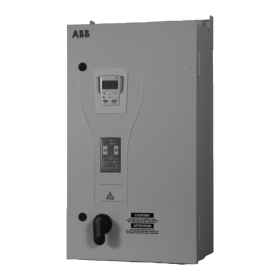
This manual is a supplement to the ACH550-UH User’s Manual and documents E-Bypass configurations. E-Bypass Features and Functions The ACH550 with E-Bypass is an ACH550 AC adjustable frequency drive in an integrated UL type 1 or UL type 12 package with a bypass motor starter. The ACH550 with E-Bypass provides: •... - Page 7 E-Bypass Configurations for ACH550 Drives The following shows the front view of the ACH550 E-Bypass vertical configuration, and identifies the major components. ACH550 Drive ACH-CP-B Control Panel Bypass Keypad Operating Handle for Disconnect Switch or Circuit Breaker E-Bypass BP0091 The following shows the front view of the ACH550 E-Bypass standard configurations, and identifies the major components.
-
Page 8: Installation Flow Chart
Contactor Installation Flow Chart The installation of E-Bypass Configurations for ACH550 drives follows the outline below. The steps must be carried out in the order shown. At the right of each step are references to the detailed information needed for the correct installation of the unit. -
Page 9: Preparing For Installation (Supplement To Ach550-Uh User's Manual)
E-Bypass Configurations for ACH550 Drives Preparing for Installation (Supplement to ACH550-UH User’s Manual) Drive Identification Drive Labels To determine the type of drive you are installing, refer to either: • Serial number label attached on upper part of the chokeplate ACH550-BC-316A-4 between the mounting holes. -
Page 10: Installing The Wiring (Supplement To Ach550-Uh User's Manual)
E-Bypass Configurations for ACH550 Drives Ratings and Frame Size The chart in the “Ratings” section of the ACH550-UH User’s Manual lists technical specifications, and identifies the drive’s frame size – significant, since some instructions in this document vary, depending on the drive’s frame size. To read the Ratings table, you need the “Output current rating”... - Page 11 Wiring Overview (Supplement to ACH550-UH User’s Manual) Connection Diagrams – Vertical E-Bypass ACH550 Vertical E-Bypass units are configured for wiring access from the bottom only. The following figure shows the Vertical E-Bypass wiring connection points. Refer to the ACH550-UH User's Manual for control connections to the drive.
- Page 12 E-Bypass Configurations for ACH550 Drives Connection Diagrams – Standard E-Bypass (Wall Mounted) ACH550 Standard E-Bypass units are configured for wiring access from the top. The following figure shows the Standard E-Bypass (wall mounted) wiring connection points. Refer to the ACH550-UH User's Manual for control connections to the drive.
- Page 13 E-Bypass Configurations for ACH550 Drives Connection Diagrams – Standard E-Bypass (R7/R8, Floor Mounted) ACH550 Standard E-Bypass units are configured for wiring access from the top. The following figure shows the Standard E-Bypass (floor mounted) wiring connection points. Refer to the ACH550-UH User's Manual for control connections to the drive.
- Page 14 Standard Configuration (R1…R4) WARNING! Check the motor and motor wiring insulation before connecting the ACH550 to line power. Follow the procedure in the ACH550-UH User’s Manual. Before proceeding with the insulation resistance measurements, check that the ACH550 is disconnected from incoming line power. Failure to disconnect line power could result in death or serious injury.
- Page 15 Standard Configuration (R1…R4) Install the Control Wiring (Supplement to ACH550-UH User’s Manual) Connect control wiring to terminal block X1 on the ACH550 control board and to terminal block X2 on the E-Bypass control board. For more information on these connections, refer to the following: •...
- Page 16 • On Terminal Block X1 inside the ACH550, analog inputs and outputs and additional digital input and relay output connections (AI1, AI2, AO1, AO2, DI3, DI4, DI5, DI6 and RO2) are available for use. Refer to the ACH550-UH User’s Manual for information about control connections on Terminal Block X1.
- Page 17 E-Bypass Configurations for ACH550 Drives Basic Control Connections for Separate Drive Run & Bypass Run Commands Terminals on ACH550 Control Board Terminal for signal cable shield Analog Input Channel 1 Analog Input Common 10 V / 10 mA Reference voltage for potentiometer...
- Page 18 If the motor’s rating is not 208 V or 480 V, 60 Hz, the MOTOR NOM VOLT and MOTOR NOM FREQ parameters will need to be properly set before proceeding. Refer to the ACH550-UH User’s Manual and set the parameters as required.
- Page 19 8. Press the Drive Select key on the bypass keypad. The Drive Select LED should be illuminated. 9. Press the HAND key on the ACH550 keypad. Note that the bottom line of the display indicates “HAND” and “RUN” and a Right Arrow. The Drive Run LED on the Bypass keypad should be illuminated.
- Page 20 7. Measure the output current in all three phases. The current should be balanced, and should not exceed the motor or drive rating. 8. Press the OFF key on the ACH550 control panel. The motor should stop. CAUTION: Check the motor rotation direction in bypass.
-
Page 21: Check E-Bypass Jumpers, Switches And Pots
E-Bypass Configurations for ACH550 Drives Check E-Bypass Jumpers, Switches and Pots The settings described in this section are factory set and, for most situations, do not require adjustment. However, it is a good practice to review these settings to confirm that they are appropriate for the configuration installed. - Page 22 E-Bypass Configurations for ACH550 Drives 208…240 Settings 208 - 240 Volt, Codes for Overload Trip Current DIP Switch Identification Frame Size Switch Code ACH550-xx-04A6-2 ACH550-xx-06A6-2 ACH550-xx-07A5-2 ACH550-xx-012A-2 ACH550-xx-017A-2 ACH550-xx-024A-2 ACH550-xx-031A-2 ACH550-xx-046A-2 ACH550-xx-059A-2 ACH550-xx-075A-2 ACH550-xx-088A-2 ACH550-xx-114A-2 ACH550-xx-143A-2 ACH550-xx-178A-2 ACH550-xx-221A-2 ACH550-xx-248A-2 Installation...
- Page 23 E-Bypass Configurations for ACH550 Drives 380…480 Settings 380 - 480 Volt, Codes for Overload Trip Current DIP Switch Identification Frame Size Switch Code 1/1.5 ACH550-xx-03A3-4 ACH550-xx-04A1-4 ACH550-xx-06A9-4 ACH550-xx-08A8-4 ACH550-xx-012A-4 ACH550-xx-015A-4 ACH550-xx-023A-4 ACH550-xx-031A-4 ACH550-xx-038A-4 ACH550-xx-044A-4 ACH550-xx-059A-4 ACH550-xx-072A-4 ACH550-xx-078A-4 ACH550-xx-077A-4 ACH550-xx-096A-4 ACH550-xx-124A-4...
- Page 24 E-Bypass Configurations for ACH550 Drives 500…600 Settings 500…600 Volt, Codes for Overload Trip Current DIP Switch Identification Frame Size Switch Code ACH550-xx-02A7-6 ACH550-xx-03A9-6 ACH550-xx-06A1-6 ACH550-xx-09A0-6 ACH550-xx-011A-6 ACH550-xx-017A-6 ACH550-xx-022A-6 ACH550-xx-027A-6 ACH550-xx-032A-6 ACH550-xx-041A-6 ACH550-xx-052A-6 ACH550-xx-062A-6 ACH550-xx-077A-6 ACH550-xx-099A-6 ACH550-xx-125A-6 ACH550-xx-144A-6 Switch Code Switch Setting Configurations...
- Page 25 Circuit Breaker Settings On an ACH550 E-Bypass with output ratings above 120 amps, the circuit breaker has adjustable switch settings for instantaneous and overload current protection. The factory default settings are practical for most applications. Refer to the “ABB SACE Instruction Sheet”...
-
Page 26: Start-Up
E-Bypass Configurations for ACH550 Drives Start-up Bypass Control Panel Features Note! For normal operation with the E-Bypass, place the ACH550 control panel in the Auto mode. The following figure shows the bypass control keypad and identifies the keys and LED indicating lights. The functions of the various keys and LEDs are described in the following paragraphs. - Page 27 The Hand LED is illuminated green when the motor has been started manually in the bypass mode. Drive Select Key The Drive Select key selects the ACH550 drive as the power source for the motor. Bypass Select Key The Bypass Select key selects the bypass as the power source for the motor.
-
Page 28: Operating Modes
Operating Modes Drive Mode Under normal conditions the system is in the Drive mode. The ACH550 drive provides power to the motor and controls its speed. The source of the drive’s start/ stop and speed commands is determined by the Auto or Hand mode selection of the drive’s keypad. - Page 29 If the system is switched to the Bypass mode, a motor that is running will stop. Bypass/Drive Mode Transfers If the ACH550 is in the Auto mode and the motor is running in the Drive mode, the motor will transfer to bypass operation and continue running if the system is switched to the Bypass mode and the bypass is in the Auto mode with the Start/Stop Input contact closed.
-
Page 30: Bypass Control Board Inputs And Outputs
The Start/Stop input is connected to a normally open contact that starts and stops the system. When the E-Bypass is in the Drive mode and the ACH550 is in the Auto mode, the Start/Stop input contact controls the motor by starting and stopping the ACH550 drive. - Page 31 • There can be no fault present in the system. The Start command can come from the bypass control board terminal block, the ACH550 keypad, the bypass keypad, or serial communications, depending on the operational mode selected. The System Started relay is ideal for use in damper actuator circuits, opening the dampers only under those conditions where the system is preparing to run the motor.
-
Page 32: Ach550 Drive Inputs And Outputs
ACH550 Drive Inputs and Outputs Some of the ACH550 inputs and outputs are pre-wired to the bypass control board and not available for external use. The inputs and outputs that are not pre-wired are available for external use by connecting directly to the terminals in the ACH550. The pre-wired and available inputs and outputs are described below. - Page 33 The ACH550 Auto Mode External Reference input is an analog input that sets the operating speed when the ACH550 HVAC macro is selected and the drive is in the Auto mode. When HVAC PID Control is selected, analog inputs are used for receiving the transducer feedback “actual”...
-
Page 34: The Bypass Application Macro
E-Bypass Configurations for ACH550 Drives The Bypass Application Macro The following figures show a variety of configurations and connections using the Bypass Macro. Basic Control Connections for Separate Drive Run & Bypass Run Commands Terminals on ACH550 Control Board Terminal for signal cable shield... - Page 35 E-Bypass Configurations for ACH550 Drives Basic Control Connections for Externally Supplied 115 VAC Power Terminals on ACH550 Control Board Terminal for signal cable shield Analog Input Channel 1 Analog Input Common 10 V / 10 mA Reference voltage for potentiometer...
- Page 36 E-Bypass Configurations for ACH550 Drives Basic Control Connections for Damper Actuator Control Terminals on ACH550 Control Board Terminal for signal cable shield Analog Input Channel 1 Analog Input Common 10 V / 10 mA Reference voltage for potentiometer 15 Digital Input 3...
- Page 37 E-Bypass Configurations for ACH550 Drives Basic Control Connections for Routing Output Through the ACH550 Terminals on ACH550 Control Board Terminal for signal cable shield Analog Input Channel 1 Analog Input Common 10 V / 10 mA Reference voltage for potentiometer...
- Page 38 E-Bypass Configurations for ACH550 Drives Worksheet Terminals on ACH550 Control Board Terminal for signal cable shield Analog Input Channel 1 Analog Input Common 10 V / 10 mA Reference voltage for potentiometer 15 Digital Input 3 ACH550 Drive 16 Digital Input 4...
-
Page 39: Technical Data
20,000 RMS symmetrical amperes (14,000 RMS symmetrical amperes for the 3 and 5 HP models). When connected to a 240 VAC power source, the ACH550 with E-Bypass with the circuit breaker option is suitable for use on a circuit capable of delivering not more than 50,000 RMS symmetrical amperes. - Page 40 E-Bypass Configurations for ACH550 Drives 208… 240 Volt Drive Input Fuse Ratings Frame Amps Bussmann Size Identification (600V) Type ACH550-xx-046A-2 JJS-80 ACH550-xx-059A-2 JJS-80 ACH550-xx-075A-2 JJS-100 ACH550-xx-088A-2 R4/R5 170M1368 ACH550-xx-114A-2 R4/R5 170M1369 ACH550-xx-143A-2 170M1370 ACH550-xx-178A-2 170M1371 ACH550-xx-221A-2 170M1372 ACH550-xx-248A-2 170M1372 380…480 Volt Fuses 380…...
- Page 41 170M1370 Line Reactor The ACH550 E-Bypass may contain optional input line reactors to provide additional input impedance on the VAC line. This impedance is in addition to the approximate 5% input impedance provided by internal reactors that are standard in the drive.
- Page 42 E-Bypass Configurations for ACH550 Drives Vertical Enclosure Terminals, 208…240 Volt Units 208…240 Volt Maximum Wire Size Capacities of Power Terminals Frame Motor Circuit Disconnect Ground Size Identification Terminal Breaker Switch Lugs Block ACH550-Vx-04A6-2 ACH550-Vx-06A6-2 ACH550-Vx-07A5-2 7 in-lbs 13 in-lbs 35 in-lbs...
- Page 43 E-Bypass Configurations for ACH550 Drives Vertical Enclosure Terminals, 500…600 Volt Units 500…600 Volt Maximum Wire Size Capacities of Power Terminals Frame Motor Circuit Disconnect Ground Size Identification Terminal Breaker Switch Lugs Block ACH550-Vx-02A7-6 ACH550-Vx-03A9-6 ACH550-Vx-06A1-6 7 in-lb 13 in-lb 35 in-lb...
- Page 44 E-Bypass Configurations for ACH550 Drives Standard Enclosure Terminals, 380…480 Volt Units 380…480 Volt Maximum Wire Size Capacities of Power Terminals Frame Motor Circuit Disconnect Ground Size Identification Terminal Breaker Switch Lugs Block 1/1.5 ACH550-Bx-03A3-4 ACH550-Bx-04A1-4 ACH550-Bx-06A9-4 ACH550-Bx-08A8-4 13 in-lbs 13 in-lbs...
- Page 45 E-Bypass Configurations for ACH550 Drives Standard Enclosure Terminals, 500…600 Volt Units 500…600 Volt Maximum Wire Size Capacities of Power Terminals Frame Motor Circuit Disconnect Ground Size Identification Terminal Breaker Switch Lugs Block ACH550-Bx-02A7-6 ACH550-Bx-03A9-6 ACH550-Bx-06A1-6 ACH550-Bx-09A0-6 13 in-lb 13 in-lb...
-
Page 46: Motor Connections (Supplement To Ach550-Uh User's Manual)
One contactor is the bypass contactor (2M) that can be used to manually connect the motor directly to the incoming power line in the event that the ACH550 is out of service. The other contactor is the ACH550 output contactor (1M) that disconnects the ACH550 from the motor when the motor is operating in the Bypass mode. -
Page 47: E- Bypass Control Panel Connections (Supplement To Ach550-Uh User's Manual)
E- Bypass Control Panel Connections (Supplement to ACH550-UH User’s Manual) Control cable requirements for connections to the E-Bypass control panel (X2) are the same as those described for the ACH550 control panel (X1). Refer to the ACH550 User’s Manual. Control Panel Connection Specifications... -
Page 48: Dimensions And Weights (Supplement To Ach550-Uh User's Manual)
E-Bypass Configurations for ACH550 Drives Dimensions and Weights (Supplement to ACH550-UH User’s Manual) Mounting Dimensions The following diagram and tables provide mounting point dimensions for wall mounted cabinets. Vertical E-Bypass Standard E-Bypass BP0063 BP0064 Vertical Enclosure, R1…R4 IP 21 / UL type 1 – Mounting Dimensions for each Frame Size Ref. - Page 49 E-Bypass Configurations for ACH550 Drives Standard Enclosure, R1…R6 IP 21 / UL type 1 and IP 54 / UL type 12 – Mounting Dimensions for each Frame Size Ref. 12.6 12.6 15.7 15.7 23.6 23.6 31.9 31.9 36.2 36.2 1175 46.3...
- Page 50 E-Bypass Configurations for ACH550 Drives Standard Enclosure, R7…R8 Weight Enclosure IP 21 / UL type 1 1000 IP 54 / UL type 12 1045 Outside Dimensions (R1…R6, Wall Mounted Units) Vertical E-Bypass, UL type 1, R1…R4 BP0064 Vertical E-Bypass, UL type 1 Dimensions Ref.
- Page 51 E-Bypass Configurations for ACH550 Drives Standard E-Bypass, UL type 1, R1…R6 BP0063 Standard E-Bypass, UL type 1, R1…R6 Dimensions Ref. 17.4 17.4 20.5 20.5 28.1 28.1 33.4 33.4 37.7 37.7 1212 47.7 1212 47.7 12.6 12.6 14.4 14.4 19.1 19.1...
- Page 52 E-Bypass Configurations for ACH550 Drives Standard E-Bypass, UL type 12, R1…R6 BP0062 Standard E-Bypass, UL type 12, R1…R6 Dimensions Ref. 18.2 18.2 21.3 21.3 28.9 28.9 36.5 36.5 1116 43.8 1116 43.8 1371 54.0 1371 54.0 12.6 12.6 14.4 14.4 19.1...
-
Page 53: Applicable Standards
IP 21 / UL type 1 2065 81.3 2065 81.3 25.9 25.9 31.7 31.7 IP 54 / UL type 12 2377 93.6 2377 93.6 25.9 25.9 Applicable Standards The E-Bypass configuration conforms to all standards listed for the ACH550-UH. Technical Data... - Page 54 ......45 ACH550 drive ......30 digital output relay contacts .
- Page 55 ACH550 drive ......30 auto ....... . 25 relay contacts .
- Page 56 E-Bypass Configurations for ACH550 Drives tests keypad control ..... . . 16 motor disconnected ....16 transfer LED .
- Page 57 E-Bypass Configurations for ACH550 Drives Index...
- Page 58 ABB Oy ABB Inc. AC Drives Automation Technologies P.O. Box 184 Low Voltage Drives FIN-00381 HELSINKI 16250 West Glendale Drive FINLAND New Berlin, WI 53151 Telephone +358 10 22 11 Telefax +358 10 22 22681 Telephone +1 262 785-3200 Internet http://www.abb.com...
Need help?
Do you have a question about the ACH550 and is the answer not in the manual?
Questions and answers